Downloaded 401 times


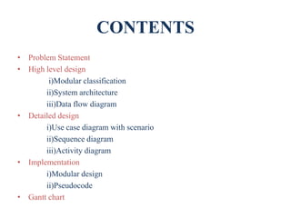
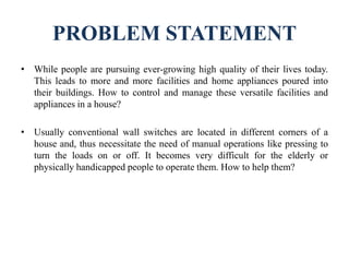

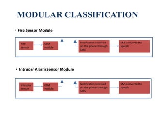
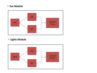
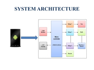
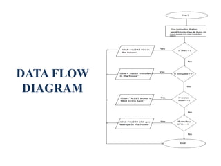

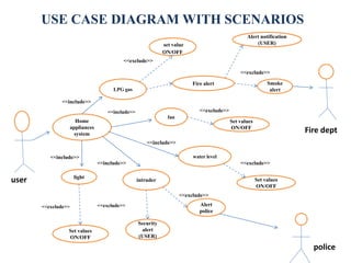


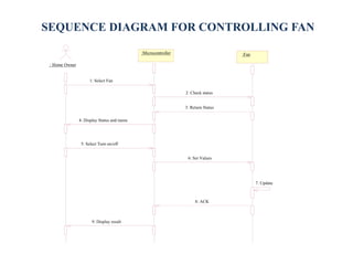
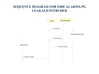

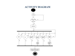

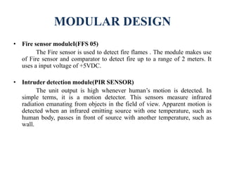
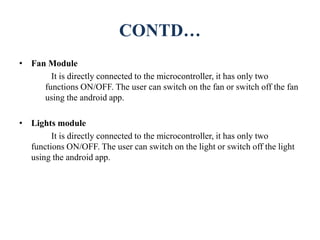
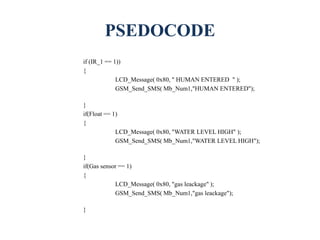
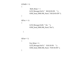
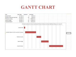


The document presents a project on an Android-based wireless load control and monitoring system designed to manage home appliances, emphasizing ease of use for the elderly and physically challenged individuals. It details the problem statement, high-level design, and modular classification, along with various components such as fire and intruder sensors connected to a microcontroller. Implementation details, including sequence diagrams and pseudocode, demonstrate how users can control devices like fans and lights through an Android app while integrating safety alerts via SMS notifications.