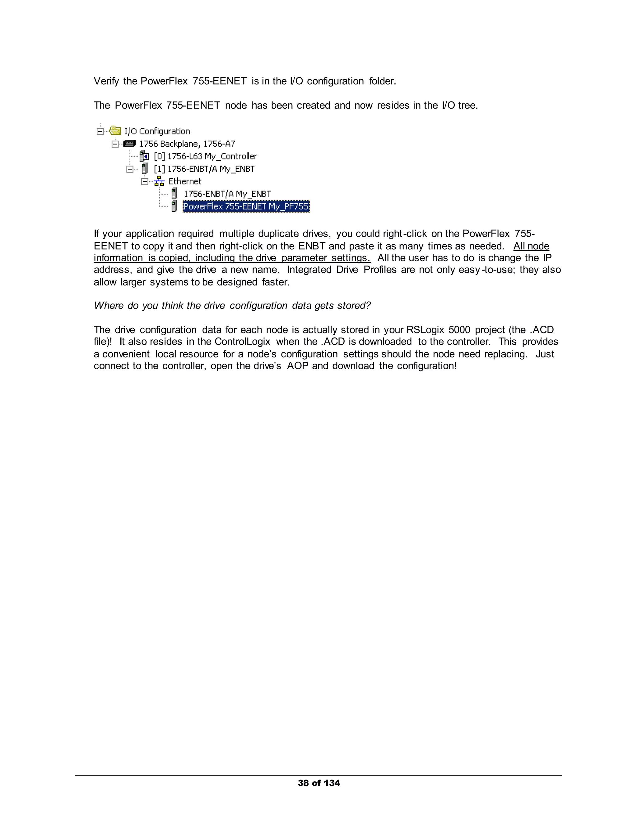
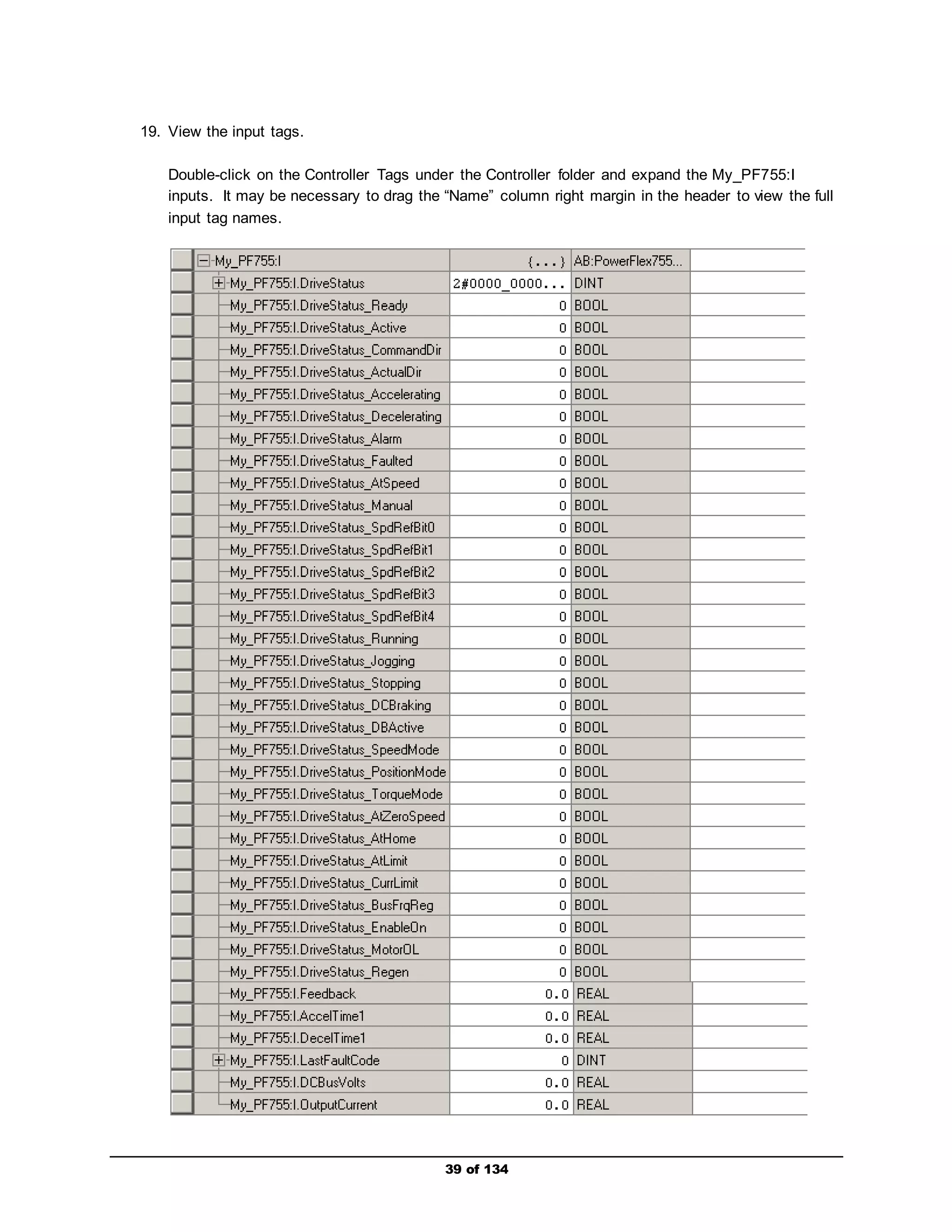
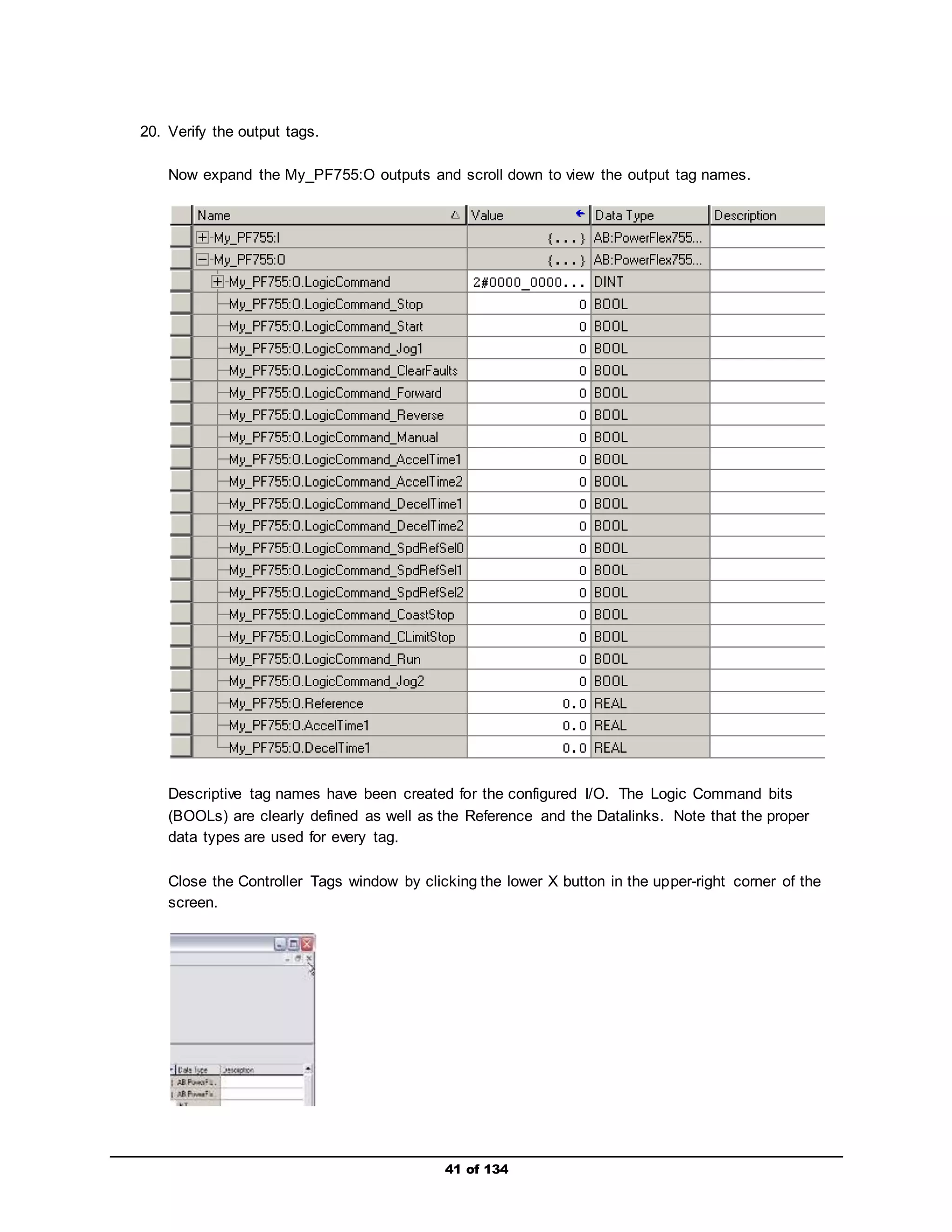
Downloaded 43 times


![29 of 134
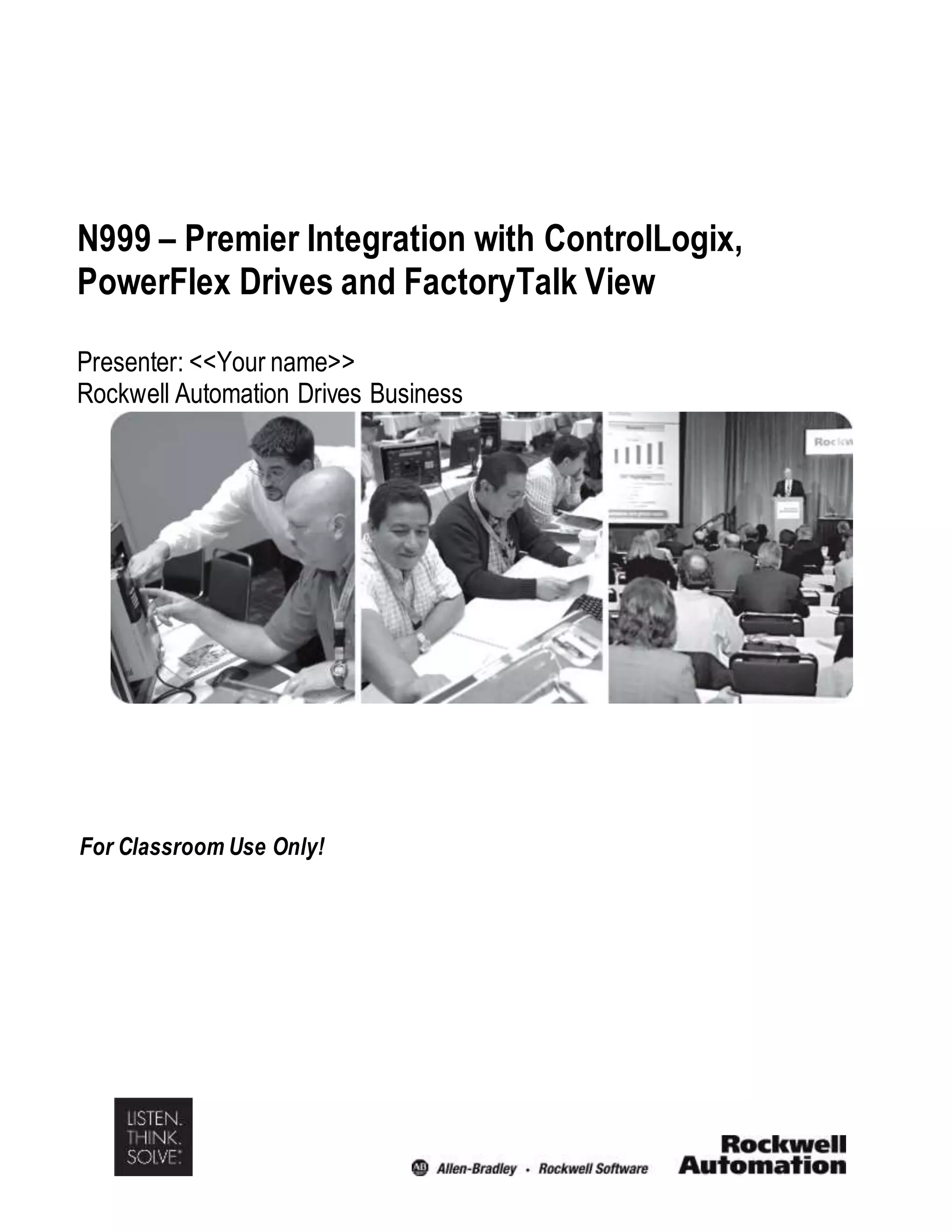
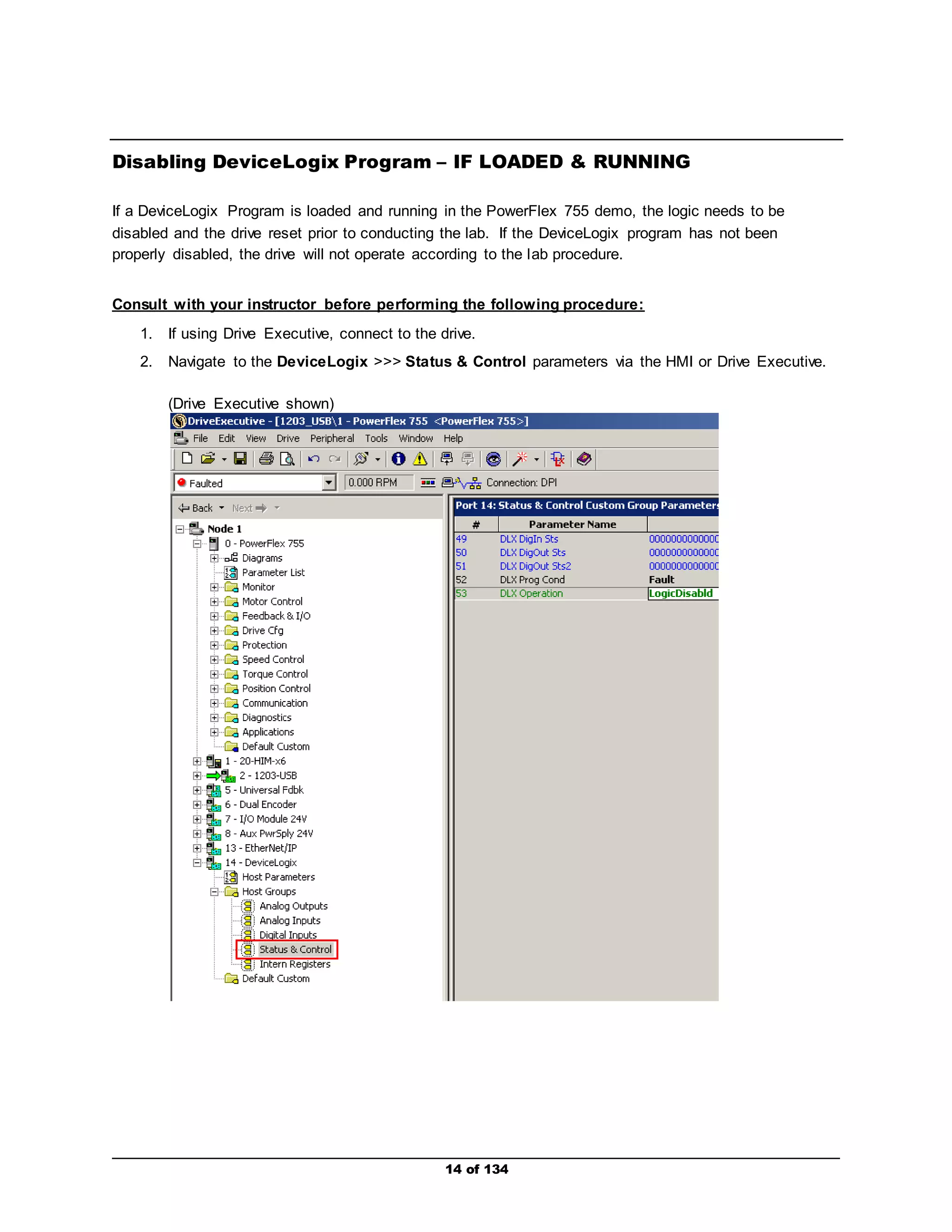
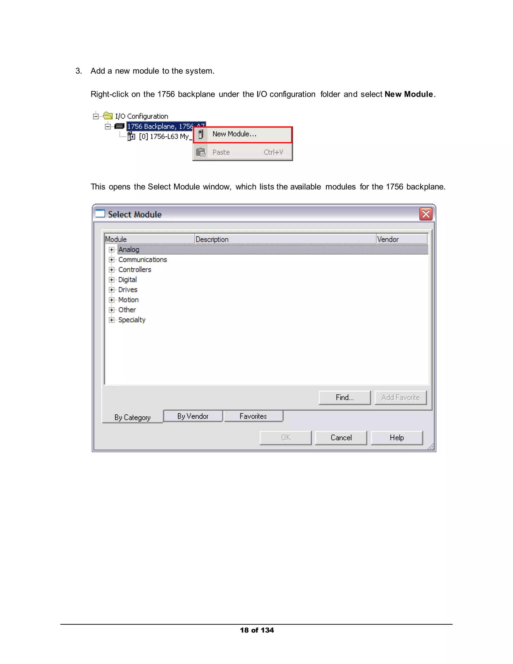
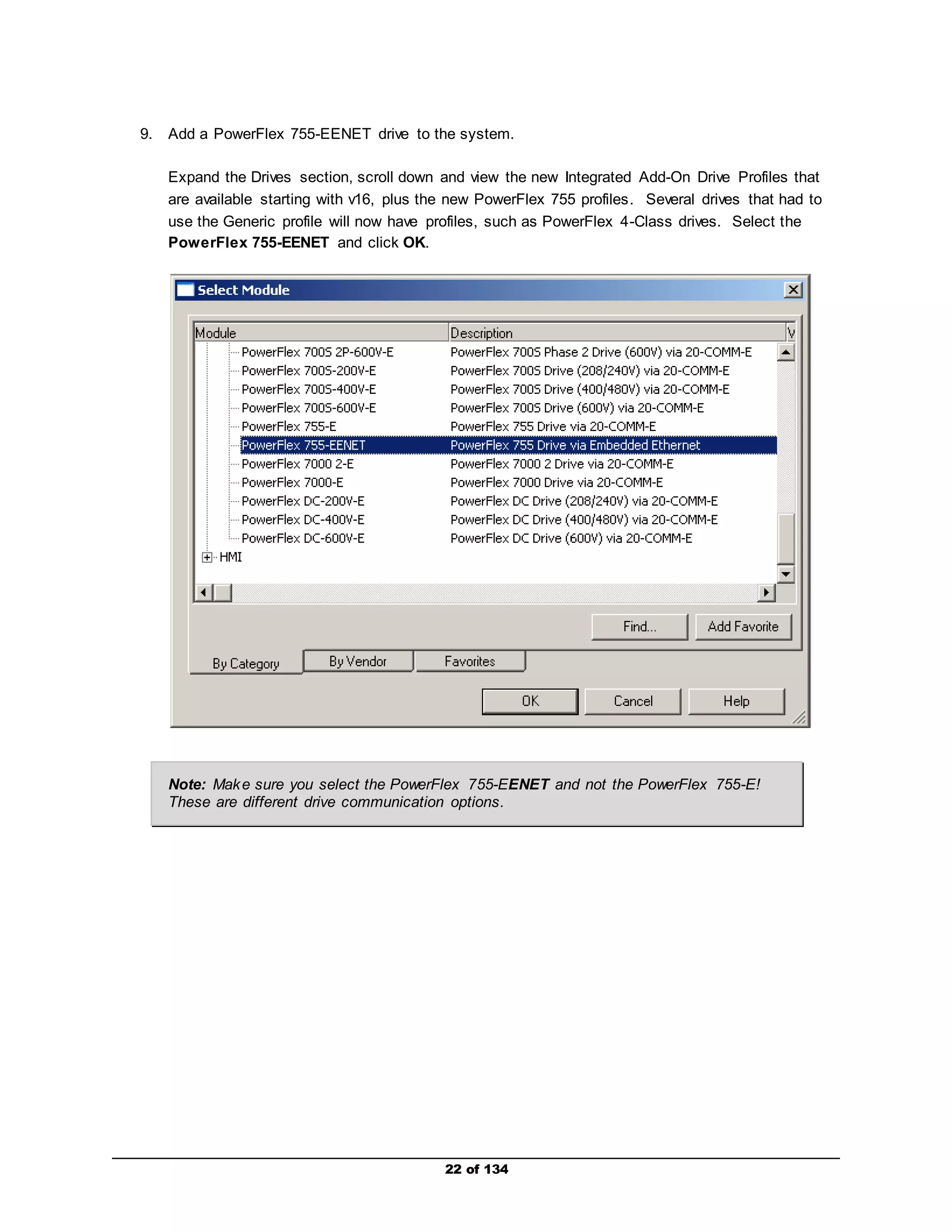
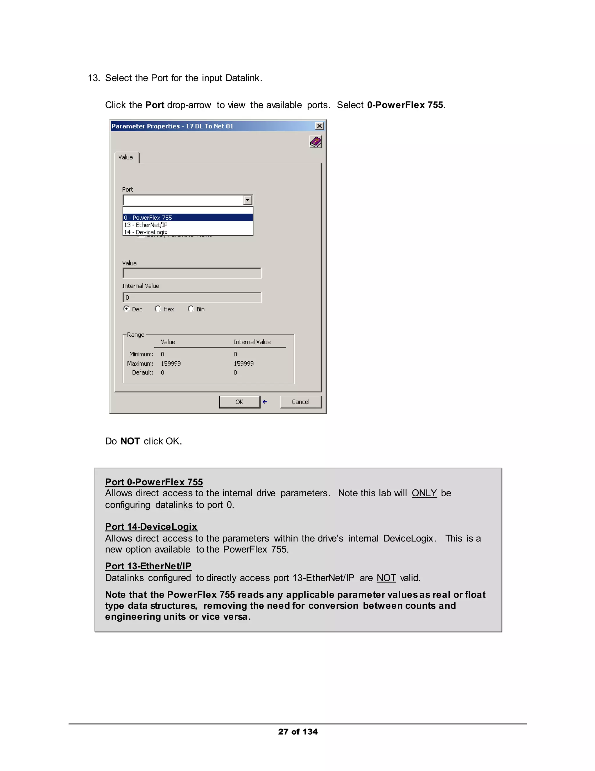
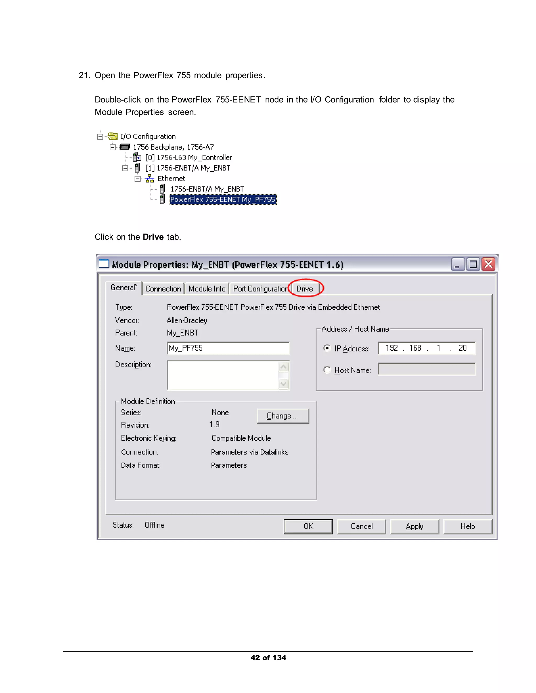
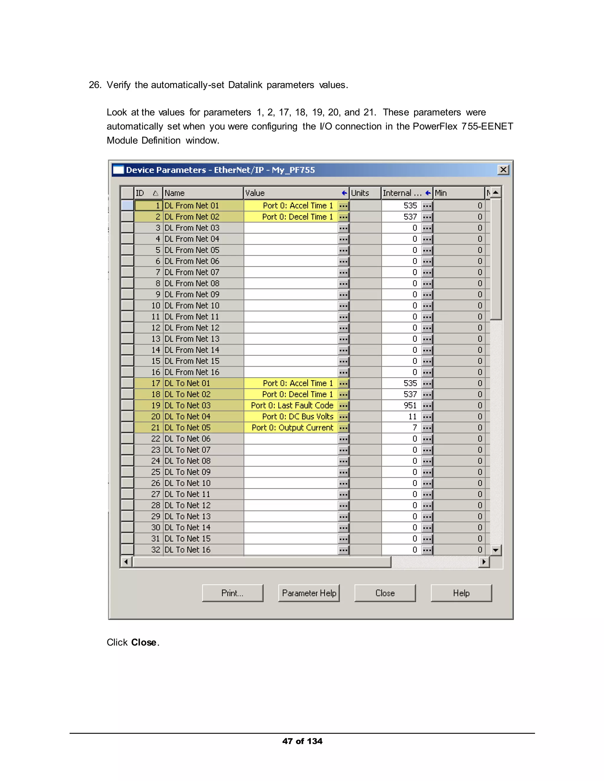
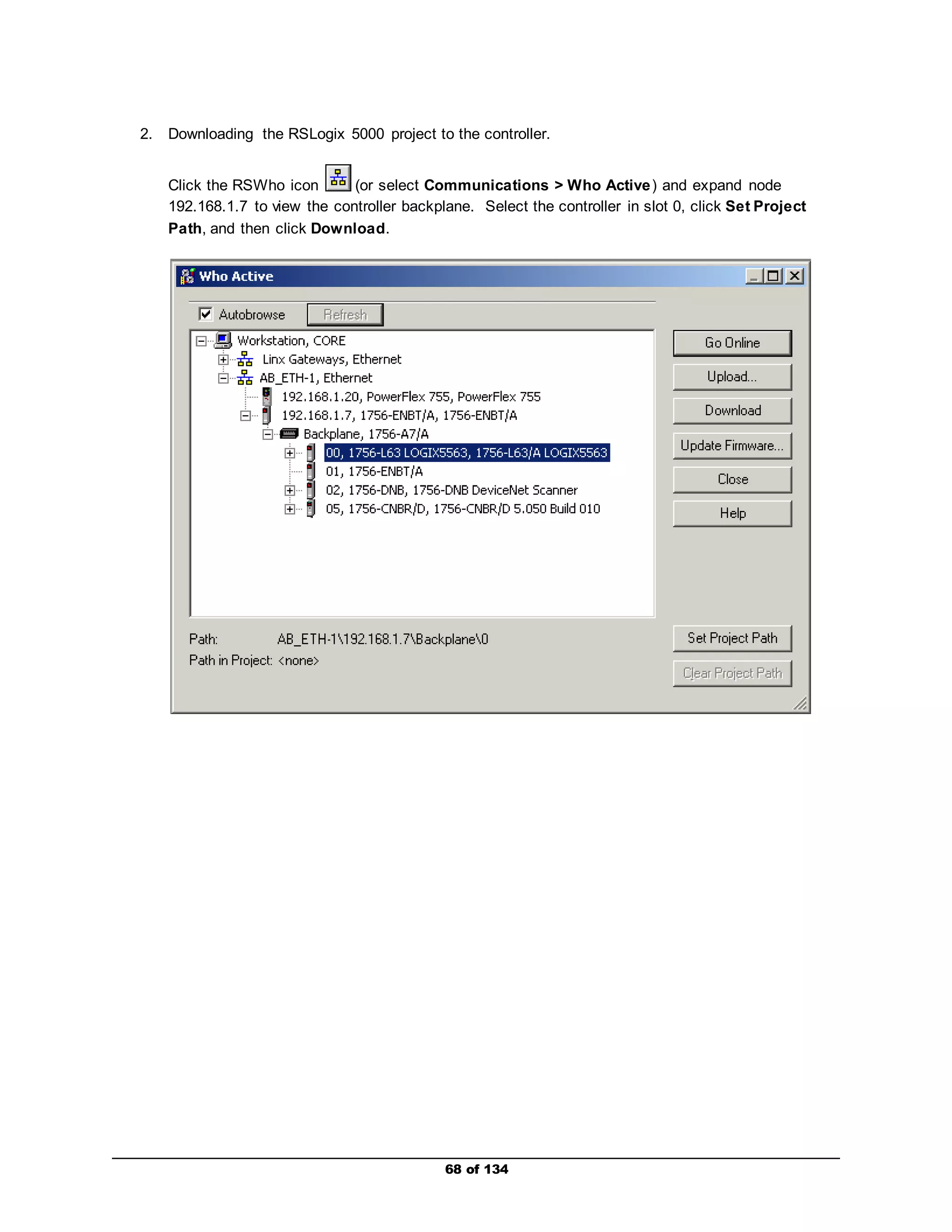
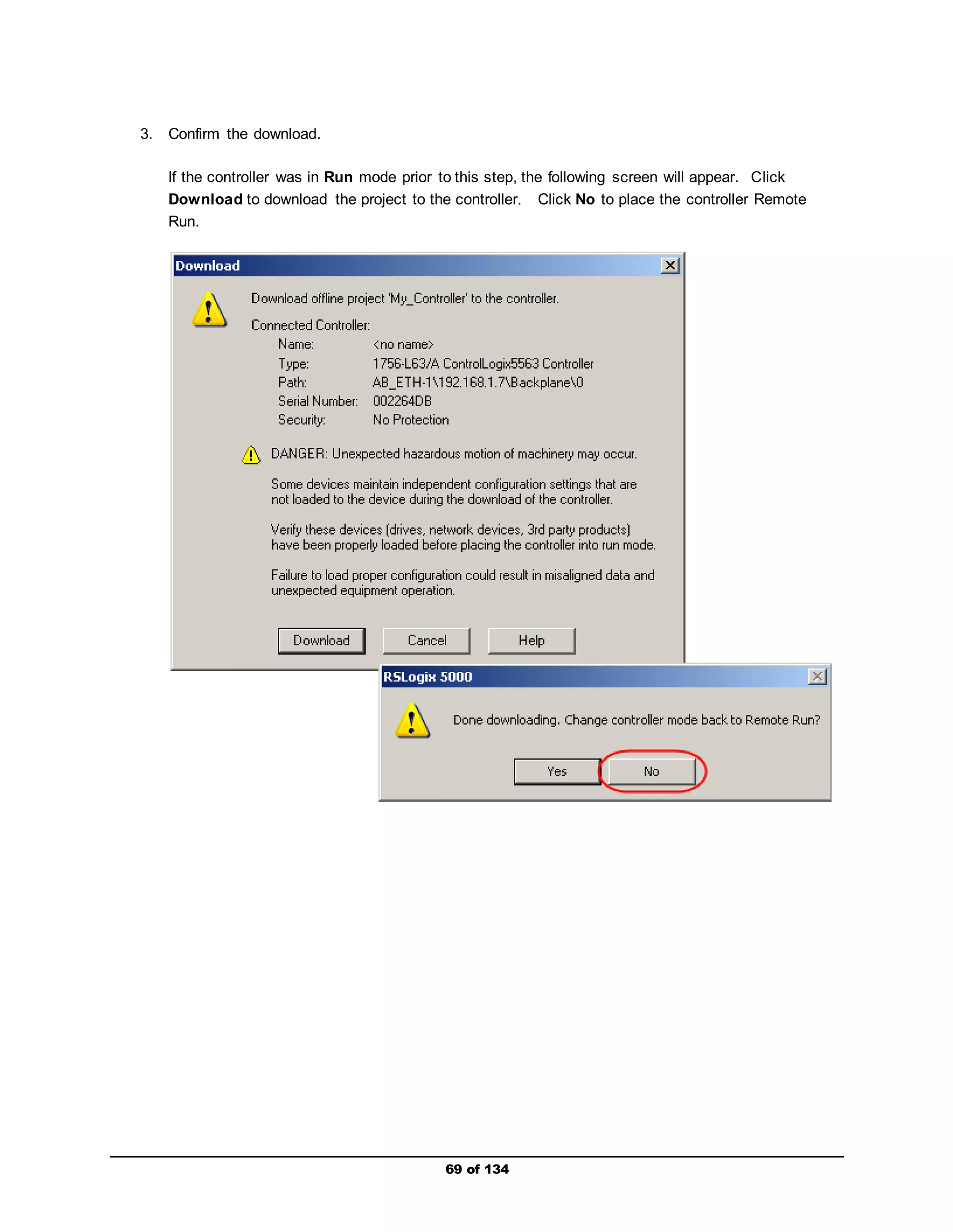
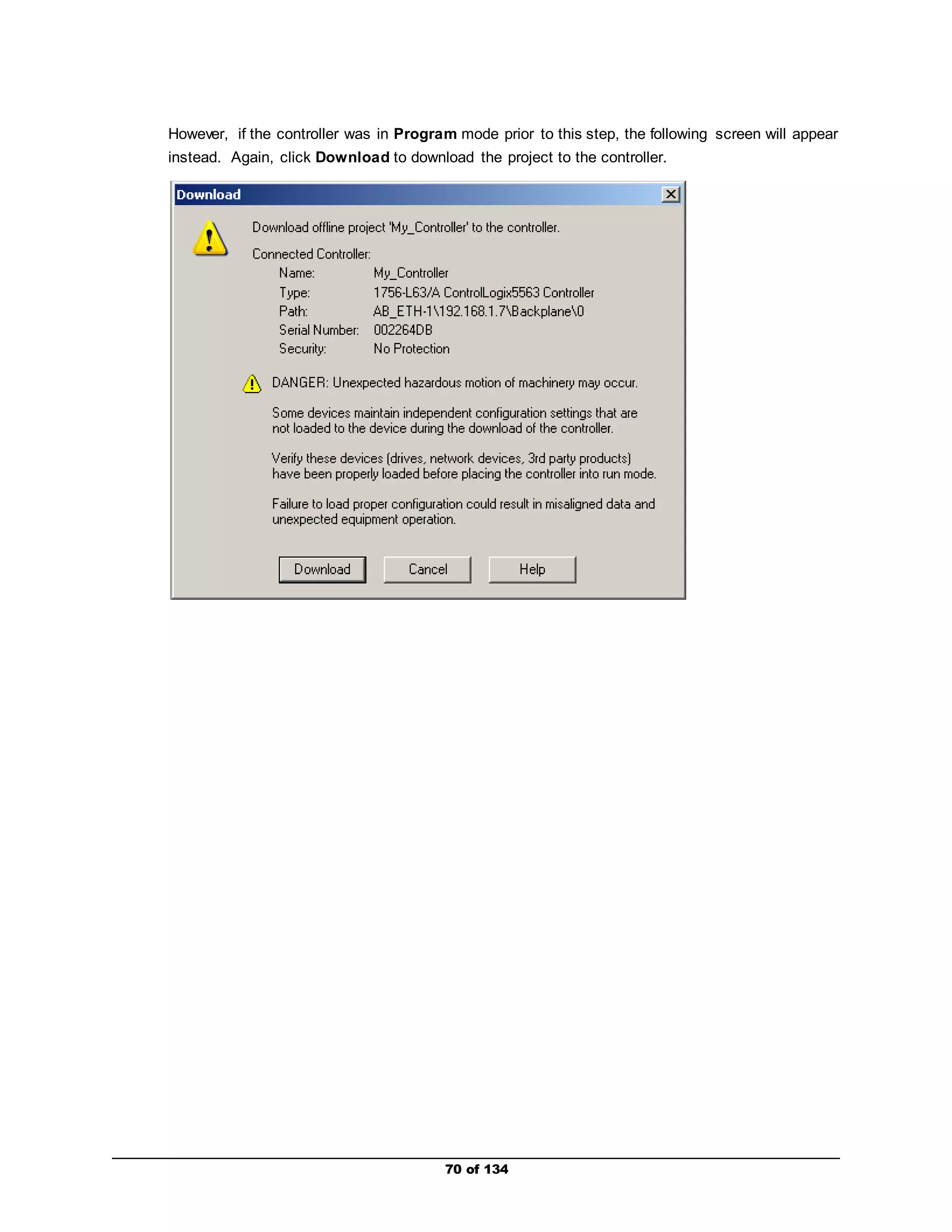
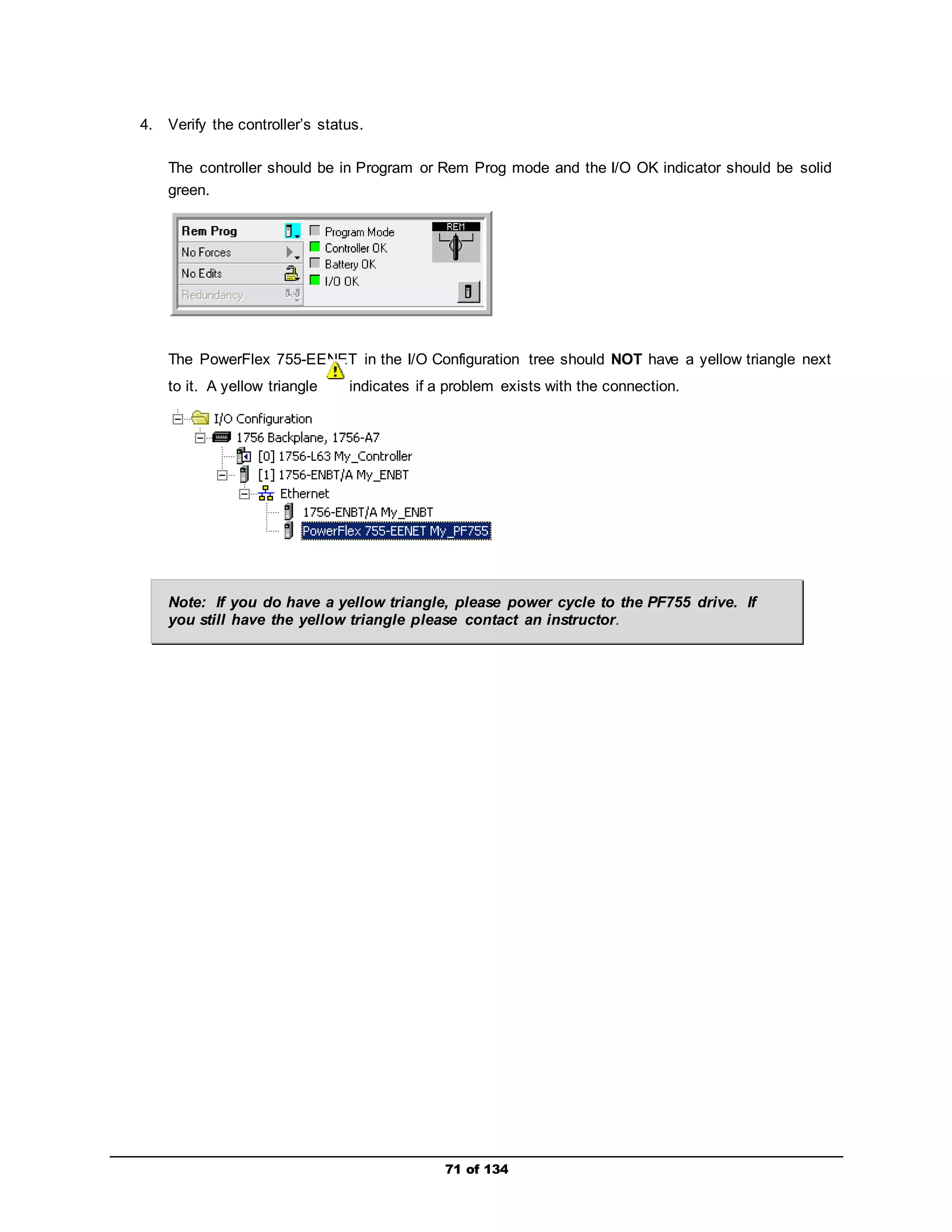
15. Observe the configured input Datalink.
You may now Click OK on the Parameter Properties window and return to module definition
screen.
Entering the input Datalink configuration automatically set the following parameter for the
Embedded EtheNet/IP module (internal to drive):
Parameter 17 [DL To Net 01] – set to Port 0: Accel Time 1
This highlights one of the benefits of the PowerFlex 755 Integrated Add-On Drive Profile:
ease-of-use. In this example, by simply selecting the desired drive parameter eliminates
the need for further configuration steps.](https://image.slidesharecdn.com/premierintegrationwithlogixpfdrivesandftviewpf755-140914194441-phpapp01/75/Premier-integration-with-logix-pf-drives-and-ft-view-pf755-29-2048.jpg)
![30 of 134
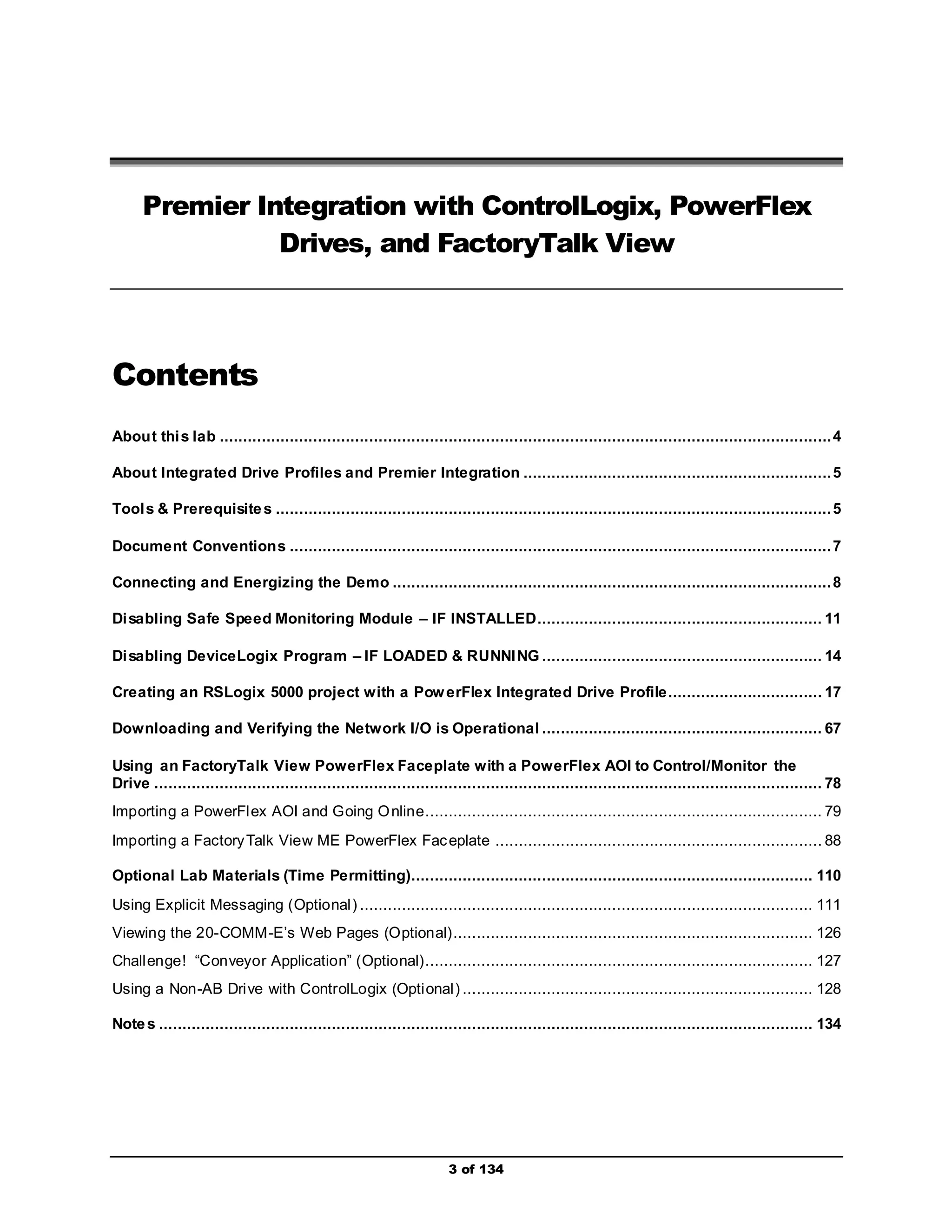
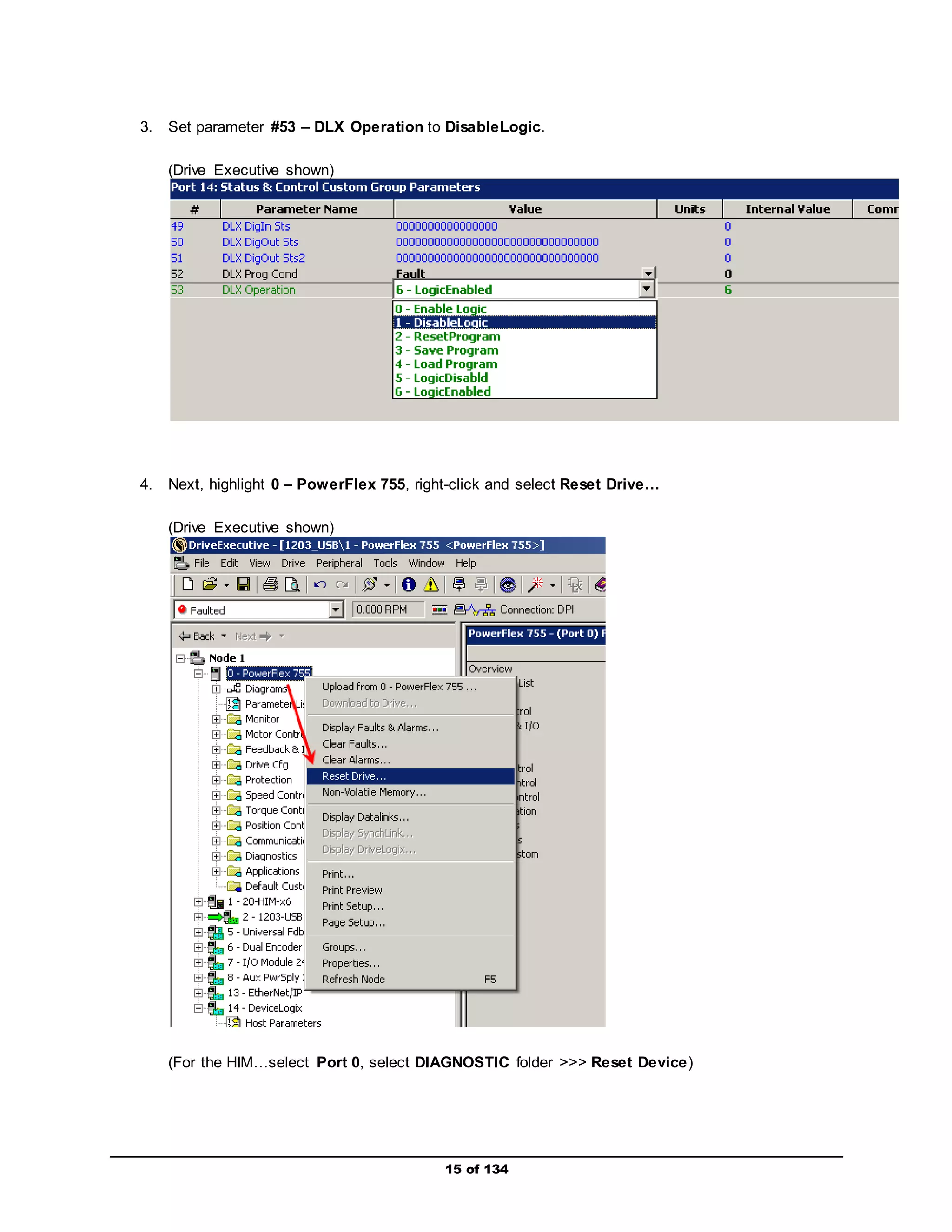
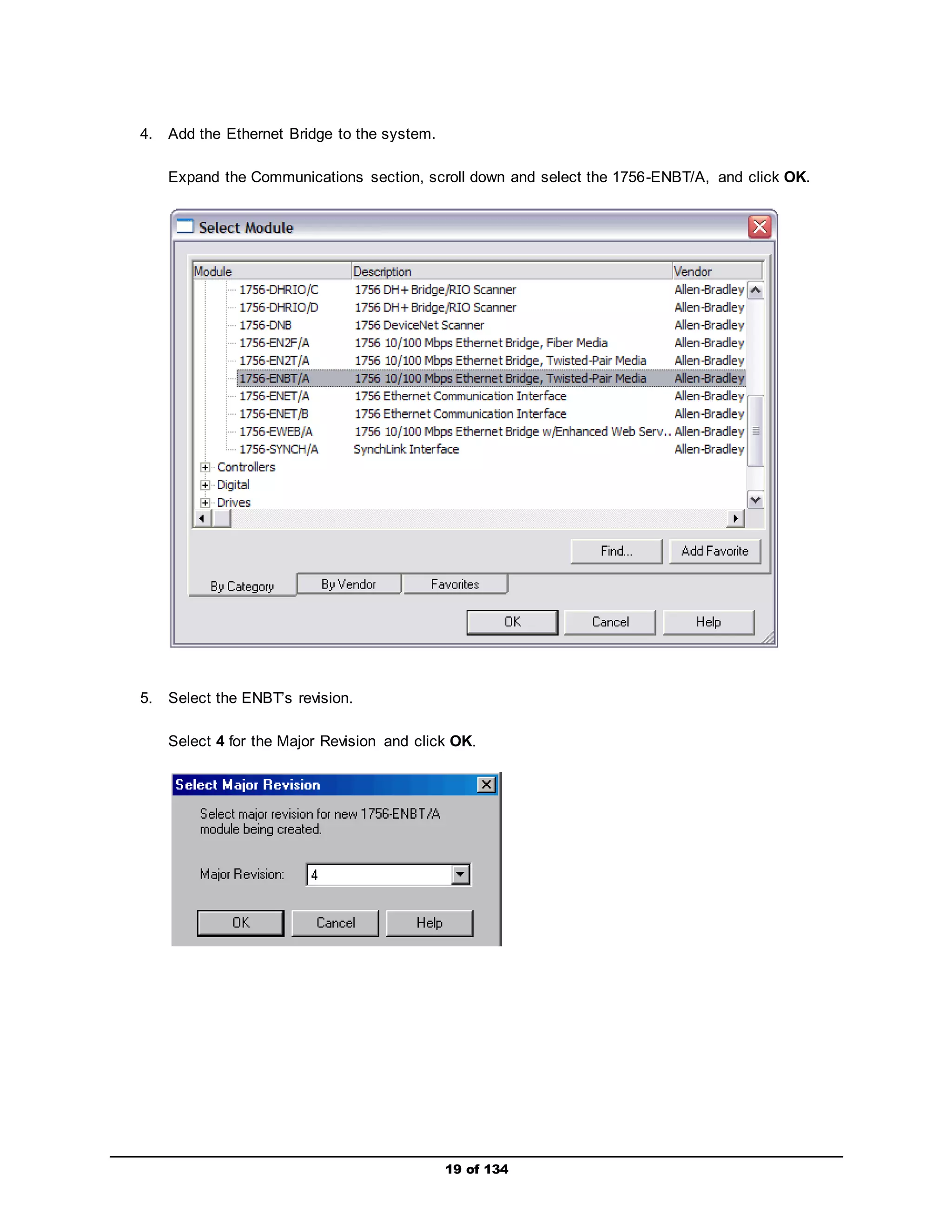
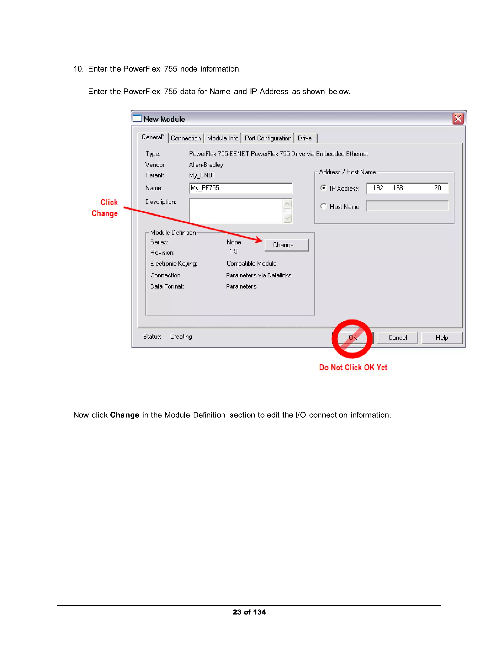
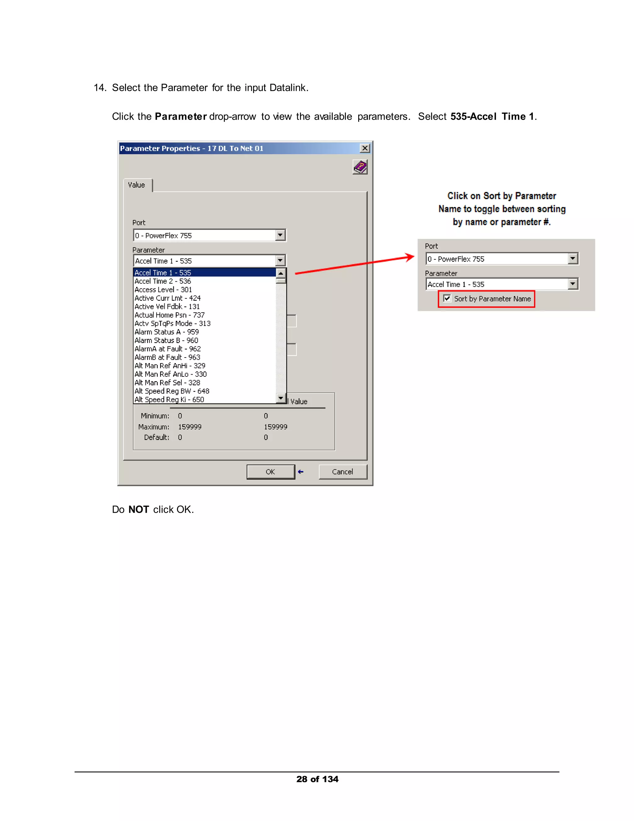
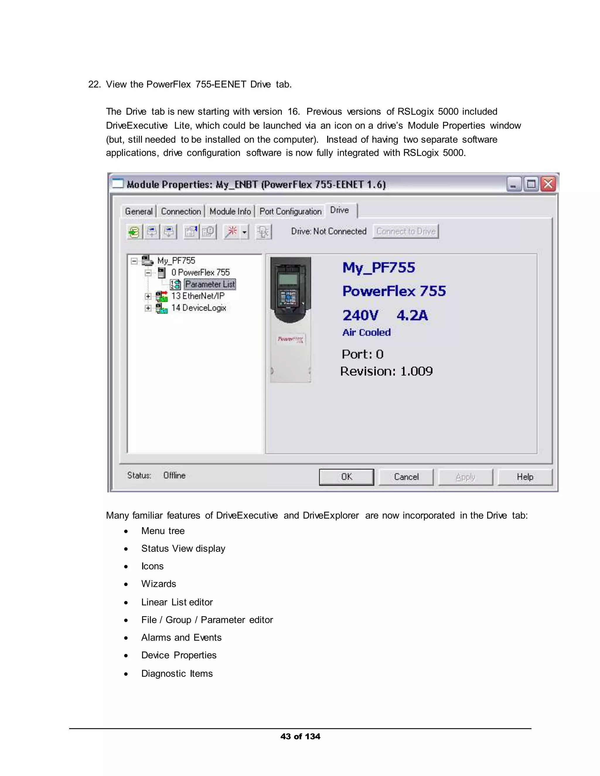
16. Configure the remaining Datalinks.
Repeat the previous steps for all of the remaining Datalinks, configure each in the order shown
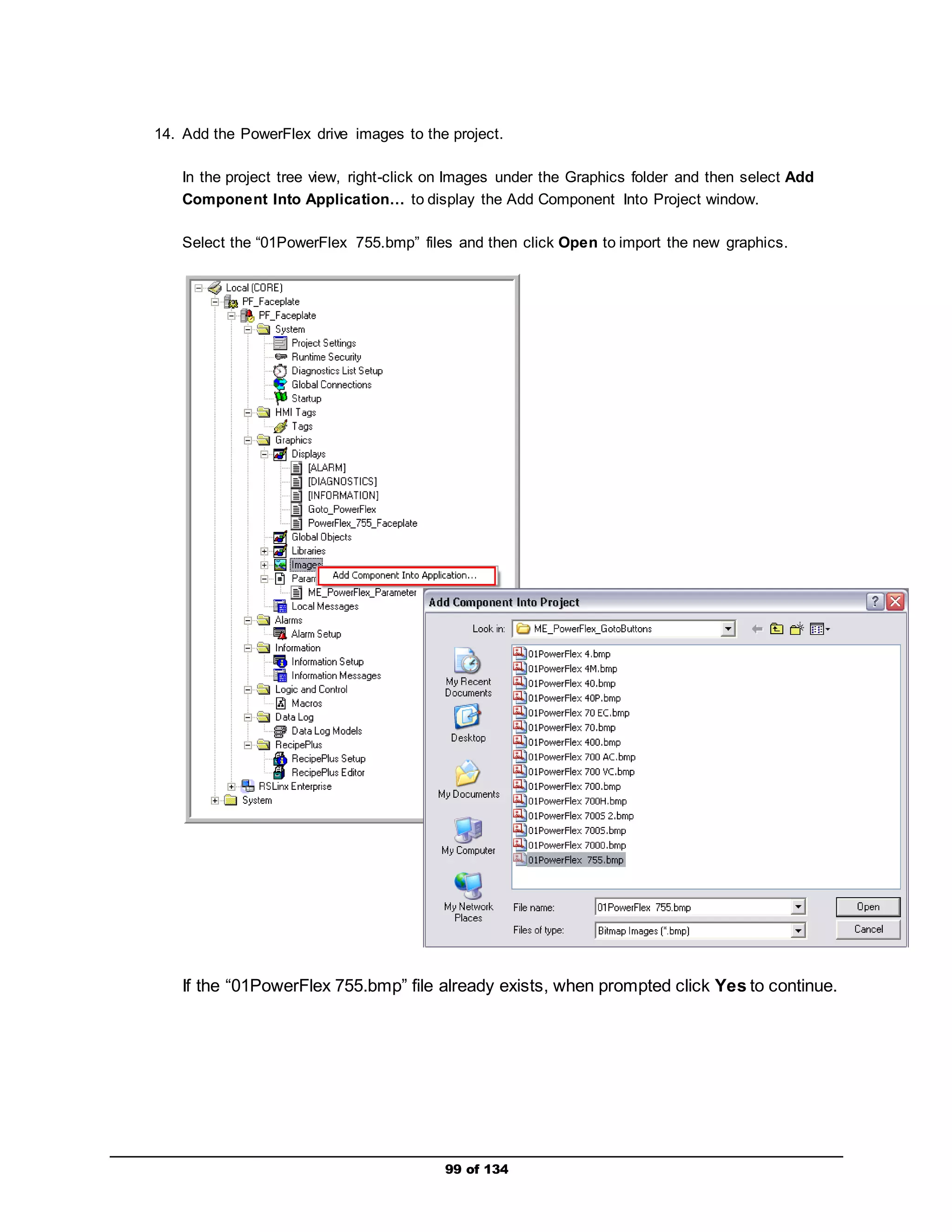
below.
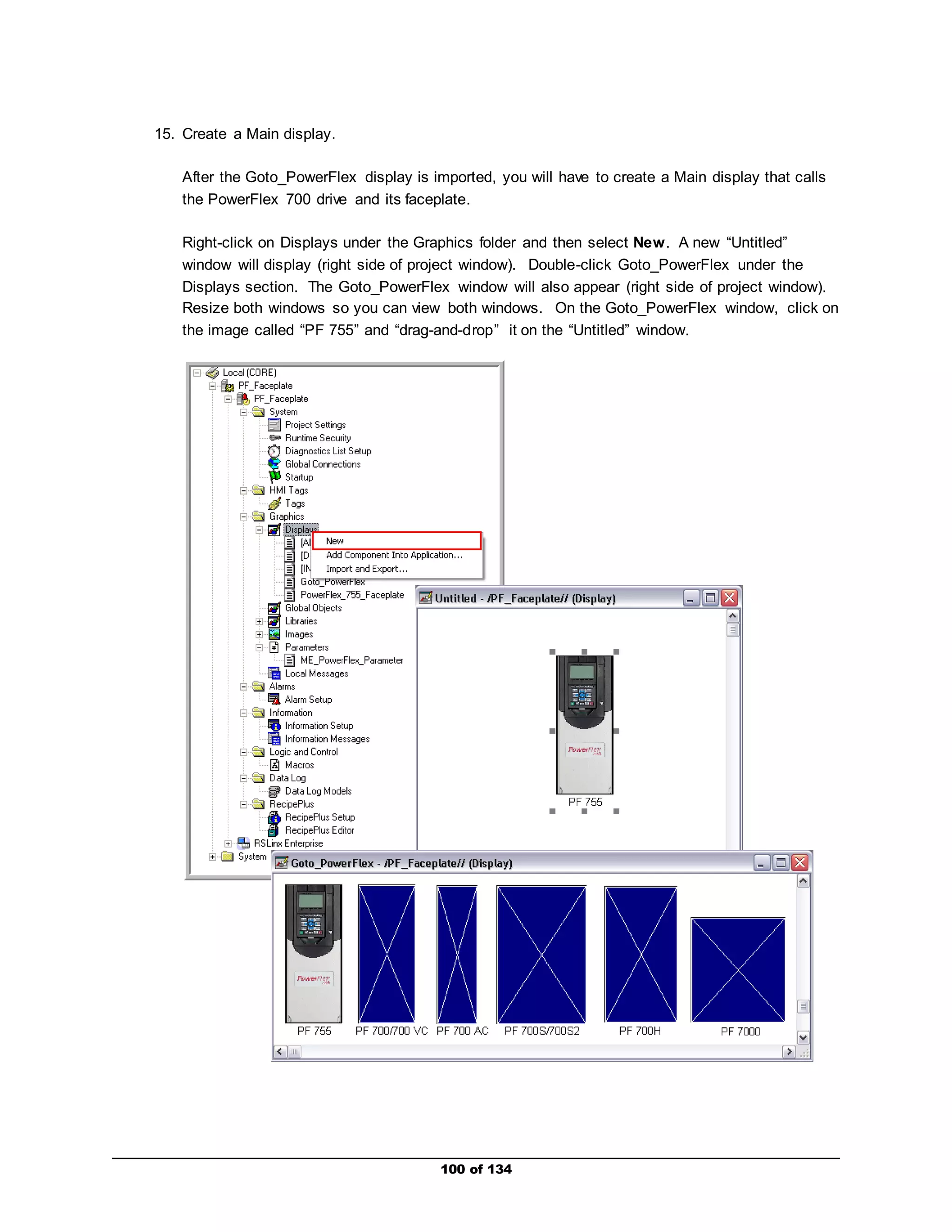
a. Input Data, Port: 0-PowerFlex 755, Parameter: Decel Time 1 – 537
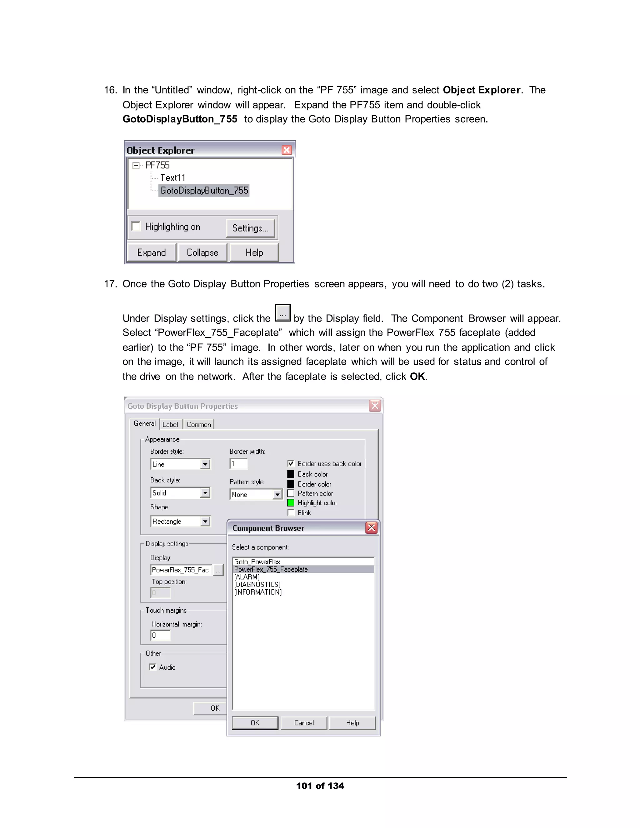
Entering the input Datalink configuration automatically set the following parameter for the
Embedded EtheNet/IP module (internal to drive):
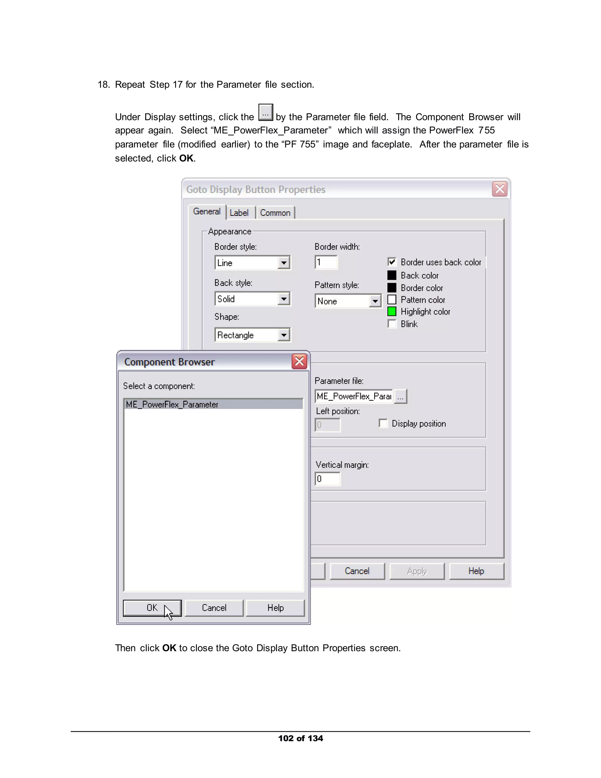
Parameter 18 [DL To Net 02] – set to Port 0: Decel Time 1](https://image.slidesharecdn.com/premierintegrationwithlogixpfdrivesandftviewpf755-140914194441-phpapp01/75/Premier-integration-with-logix-pf-drives-and-ft-view-pf755-30-2048.jpg)
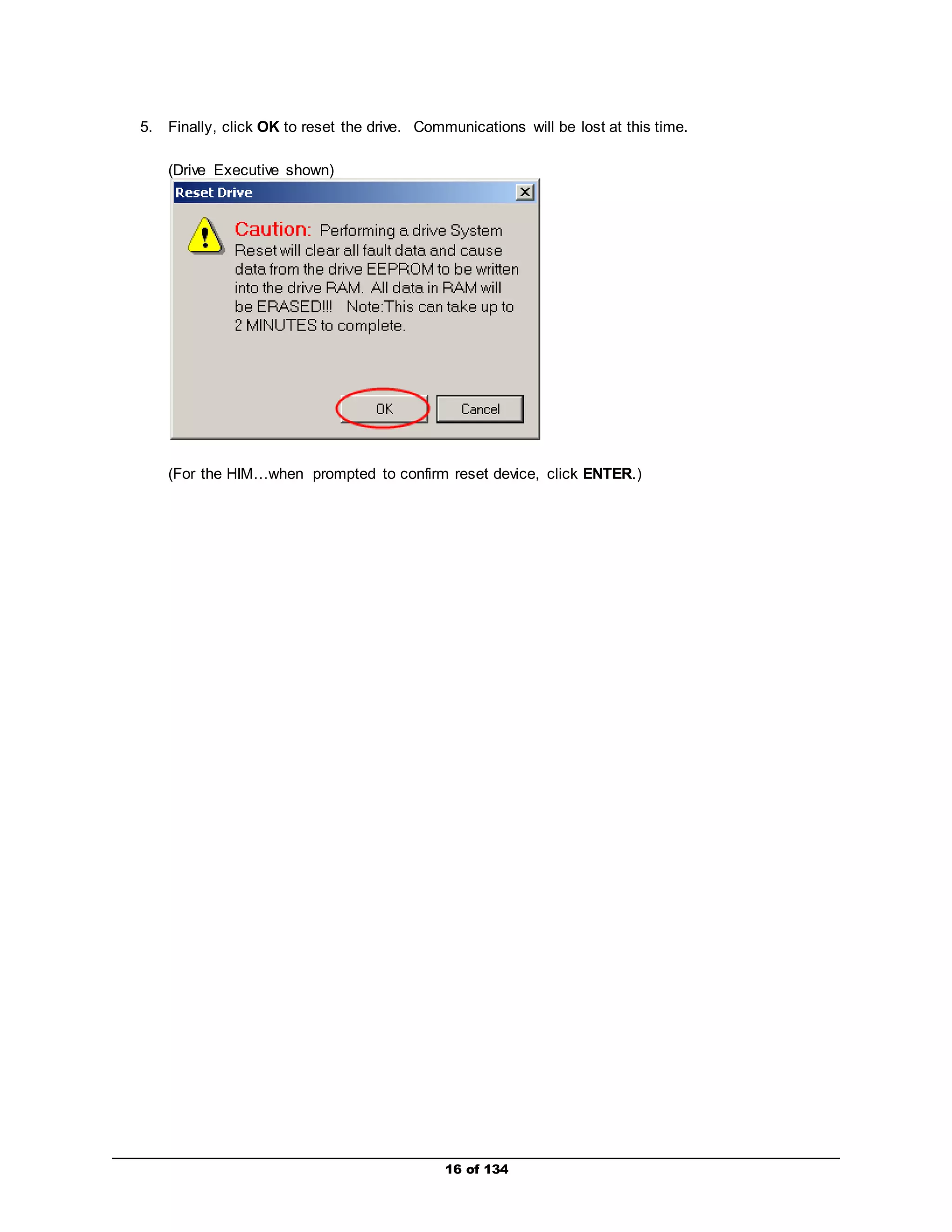
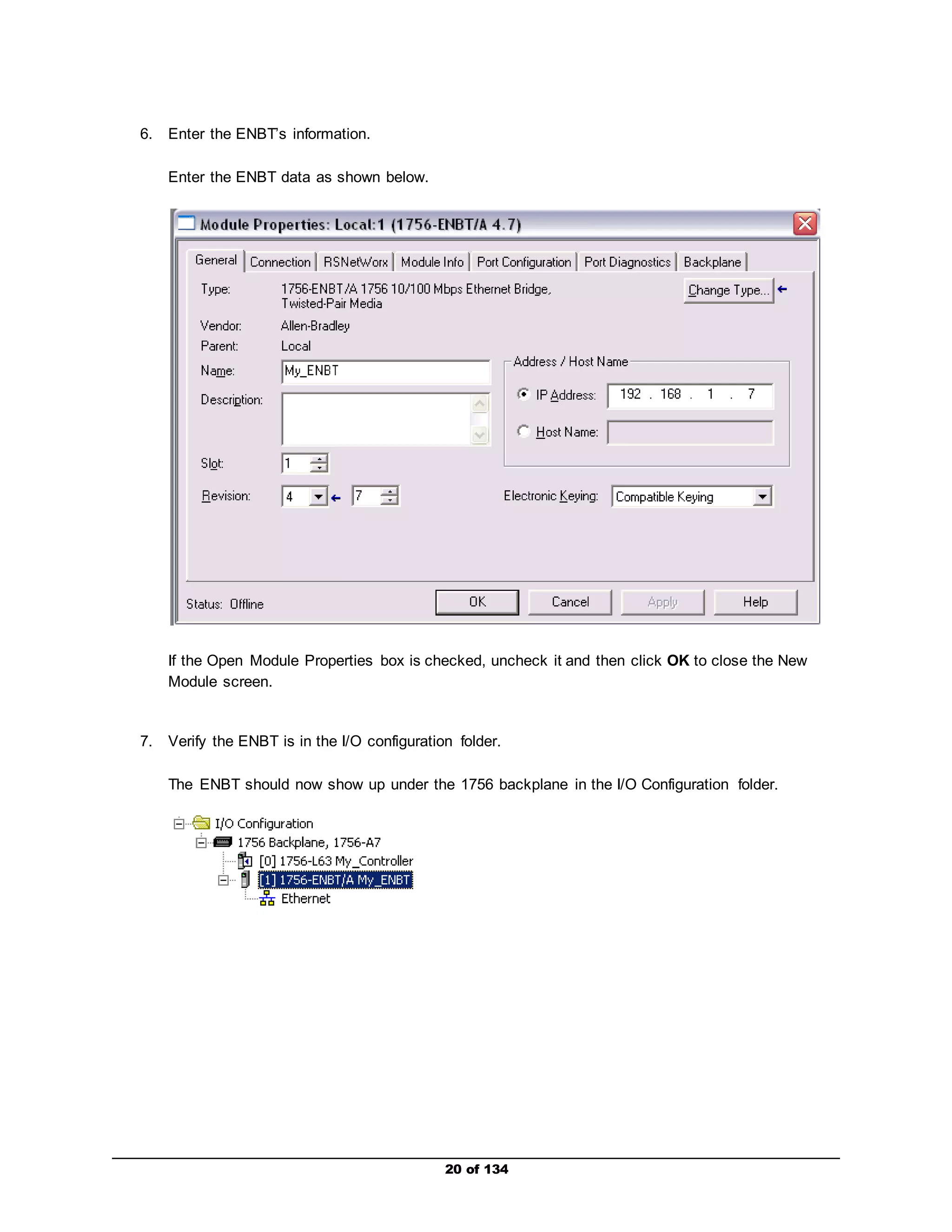
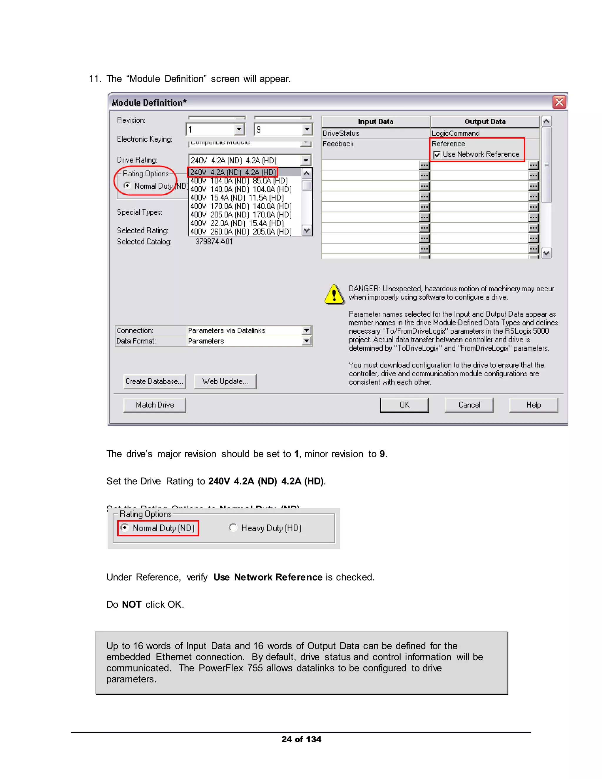
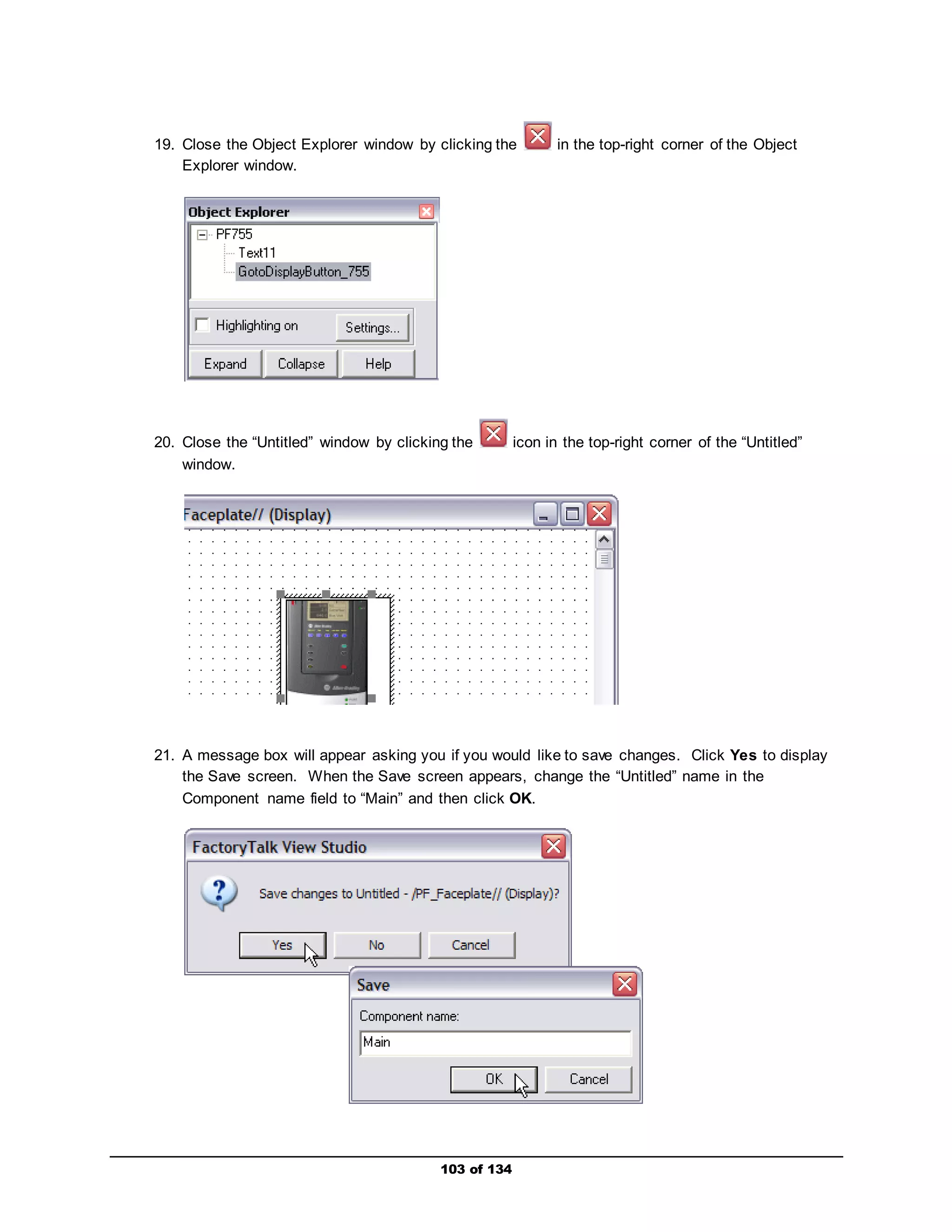
![b. Input Data, Port: 0-PowerFlex 755, Parameter: Last Fault Code – 951
Entering the input Datalink configuration automatically set the following parameter for the
Embedded EtheNet/IP module (internal to drive):
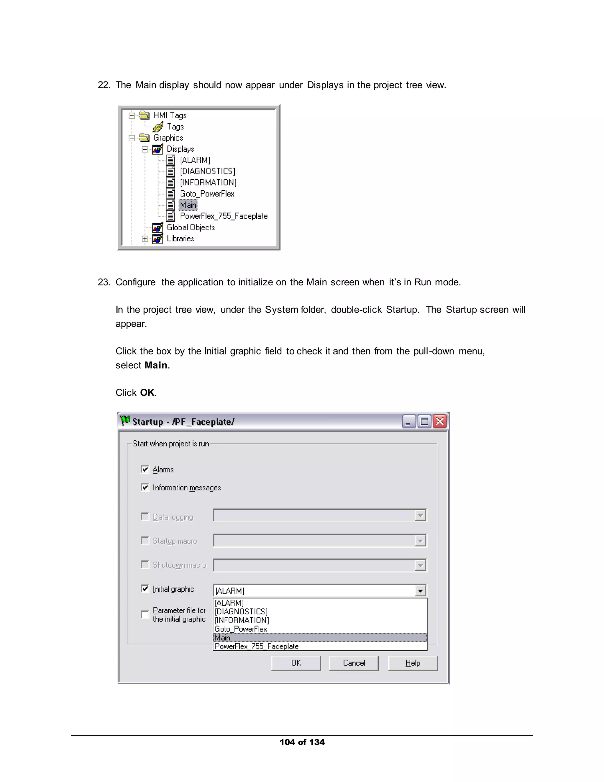
Parameter 19 [DL To Net 03] – set to Port 0: Last Fault Code
31 of 134](https://image.slidesharecdn.com/premierintegrationwithlogixpfdrivesandftviewpf755-140914194441-phpapp01/75/Premier-integration-with-logix-pf-drives-and-ft-view-pf755-31-2048.jpg)
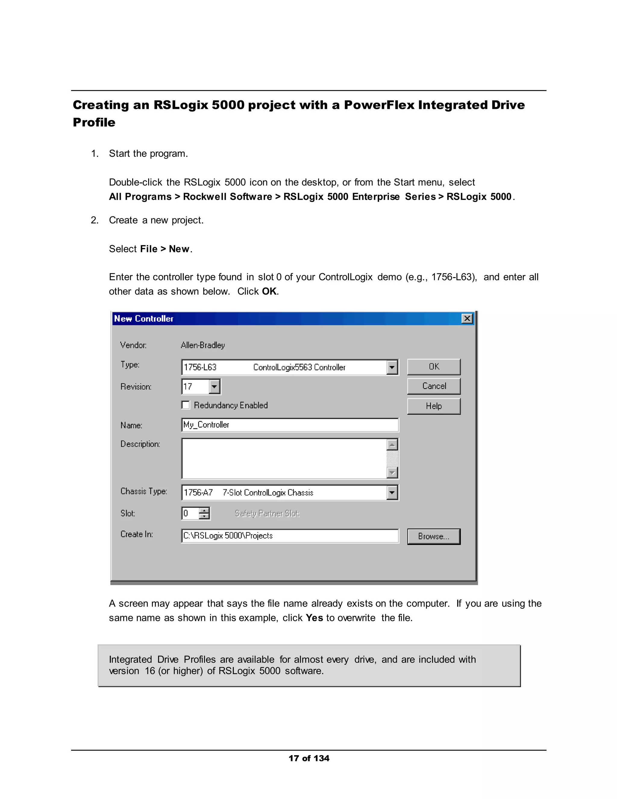
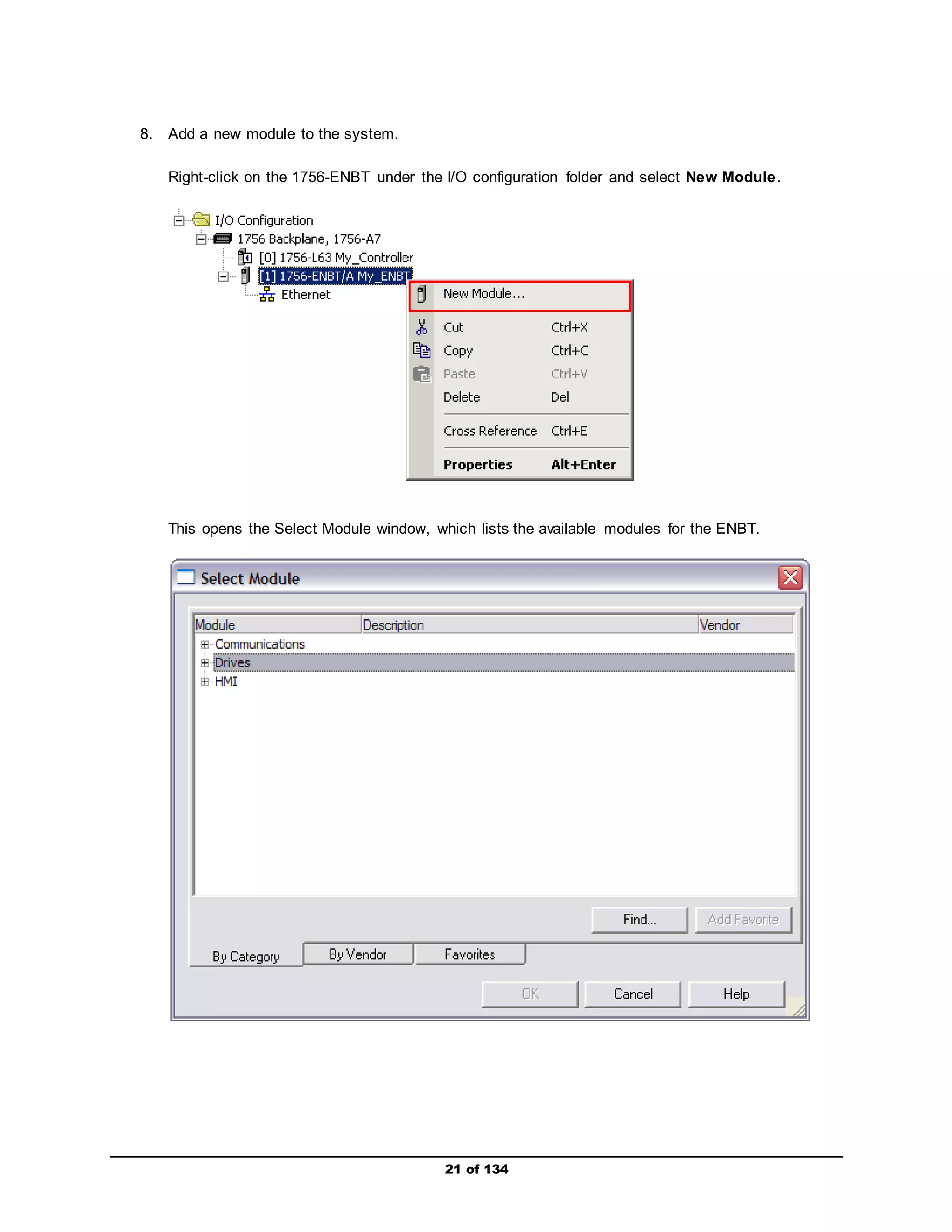
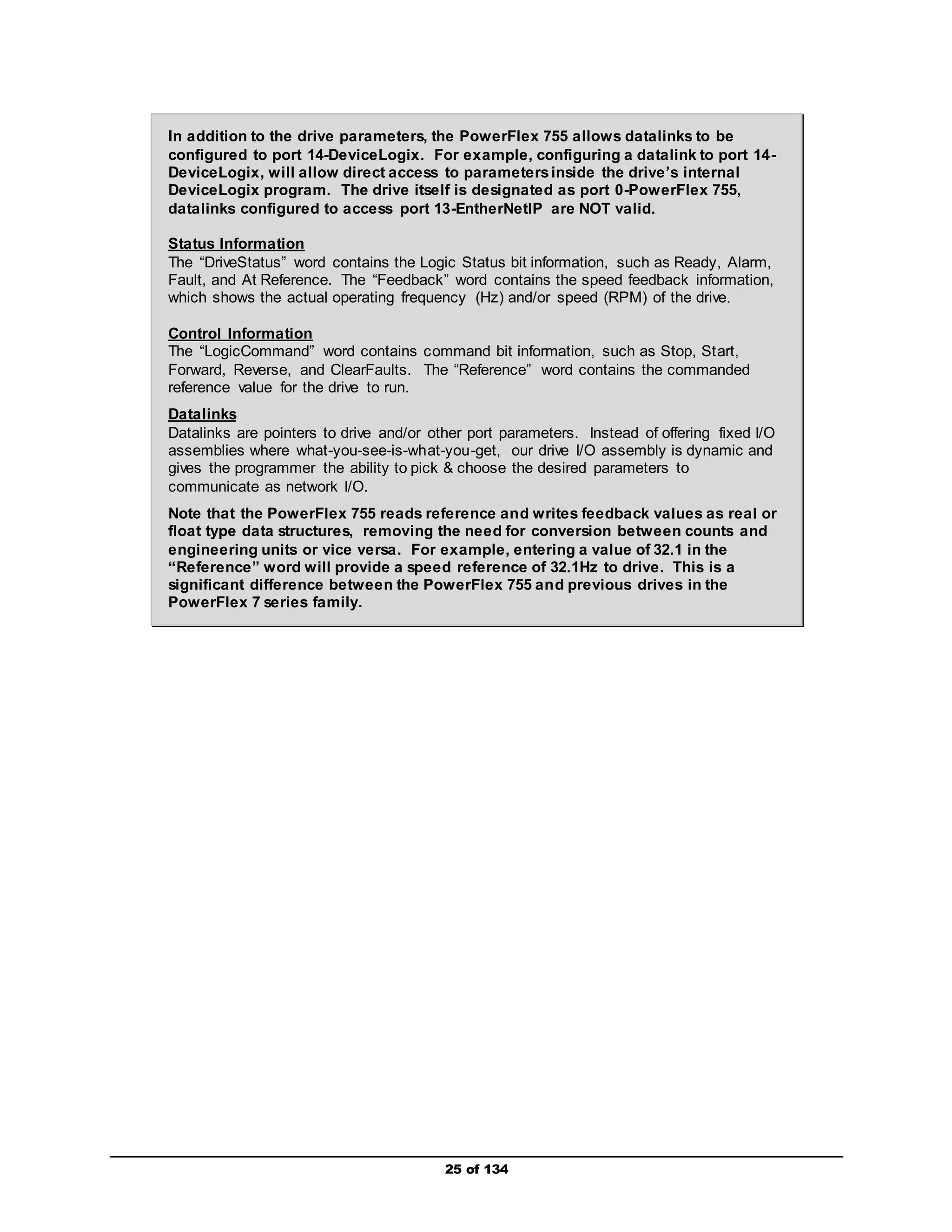
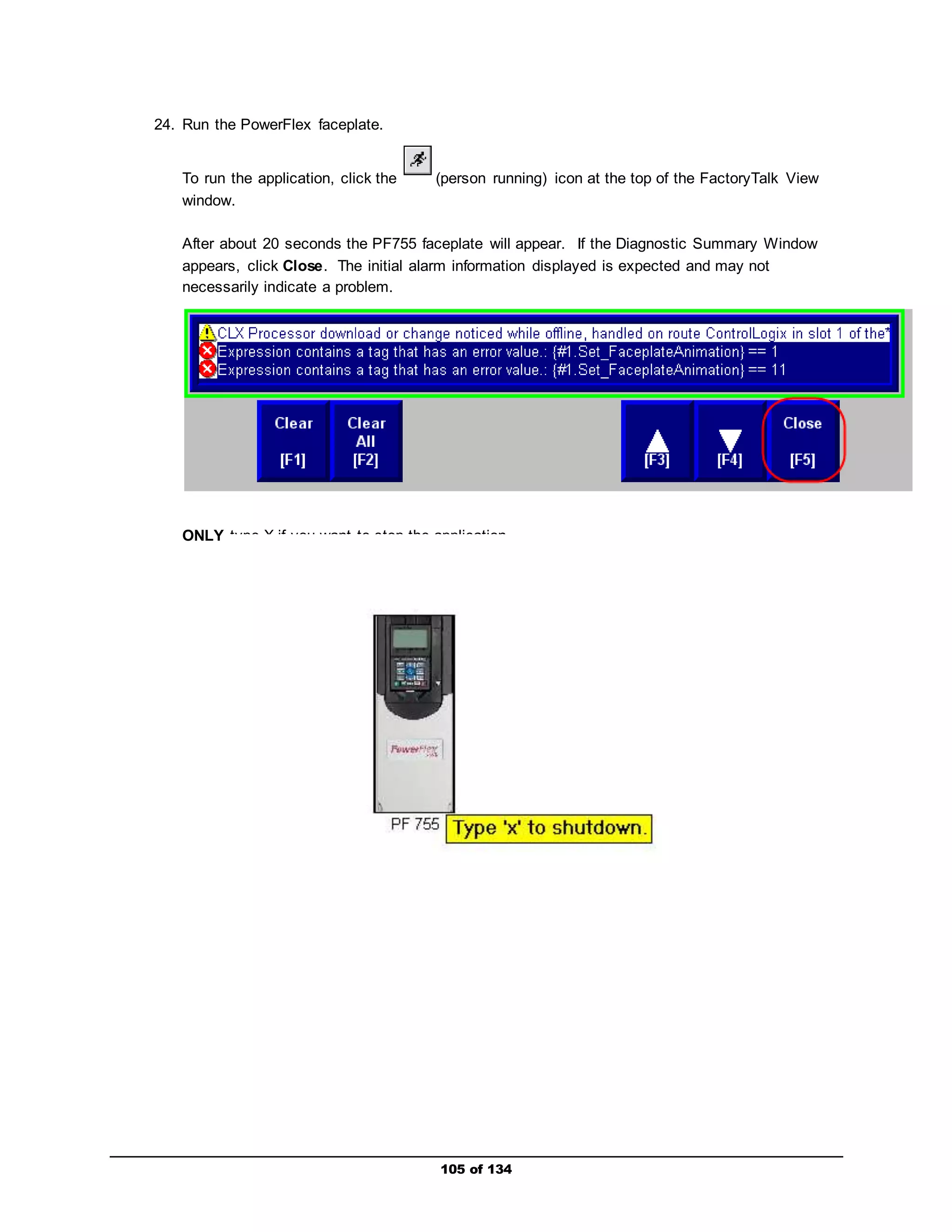
![c. Input Data, Port: 0-PowerFlex 755, Parameter: DC Bus Volts – 11
Entering the input Datalink configuration automatically set the following parameter for the
Embedded EtheNet/IP module (internal to drive):
Parameter 20 [DL To Net 04] – set to Port 0: DC Bus Volts
32 of 134](https://image.slidesharecdn.com/premierintegrationwithlogixpfdrivesandftviewpf755-140914194441-phpapp01/75/Premier-integration-with-logix-pf-drives-and-ft-view-pf755-32-2048.jpg)
![d. Input Data, Port: 0-PowerFlex 755, Parameter: Output Current – 7
Entering the input Datalink configuration automatically set the following parameter for the
Embedded EtheNet/IP module (internal to drive):
Parameter 21 [DL To Net 05] – set to Port 0: Output Current
33 of 134](https://image.slidesharecdn.com/premierintegrationwithlogixpfdrivesandftviewpf755-140914194441-phpapp01/75/Premier-integration-with-logix-pf-drives-and-ft-view-pf755-33-2048.jpg)
![e. Output Data, Port: 0-PowerFlex 755, Parameter: Accel Time 1 – 535
Entering the input Datalink configuration automatically set the following parameter for the
Embedded EtheNet/IP module (internal to drive):
Parameter 1 [DL From Net 01] – set to Port 0: Accel Time 1
34 of 134](https://image.slidesharecdn.com/premierintegrationwithlogixpfdrivesandftviewpf755-140914194441-phpapp01/75/Premier-integration-with-logix-pf-drives-and-ft-view-pf755-34-2048.jpg)
![f. Output Data, Port: 0-PowerFlex 755, Parameter: Decel Time 1 – 537
Entering the input Datalink configuration automatically set the following parameter for the
Embedded EtheNet/IP module (internal to drive):
Parameter 1 [DL From Net 02] – set to Port 0: Decel Time 1
35 of 134](https://image.slidesharecdn.com/premierintegrationwithlogixpfdrivesandftviewpf755-140914194441-phpapp01/75/Premier-integration-with-logix-pf-drives-and-ft-view-pf755-35-2048.jpg)


![74 of 134
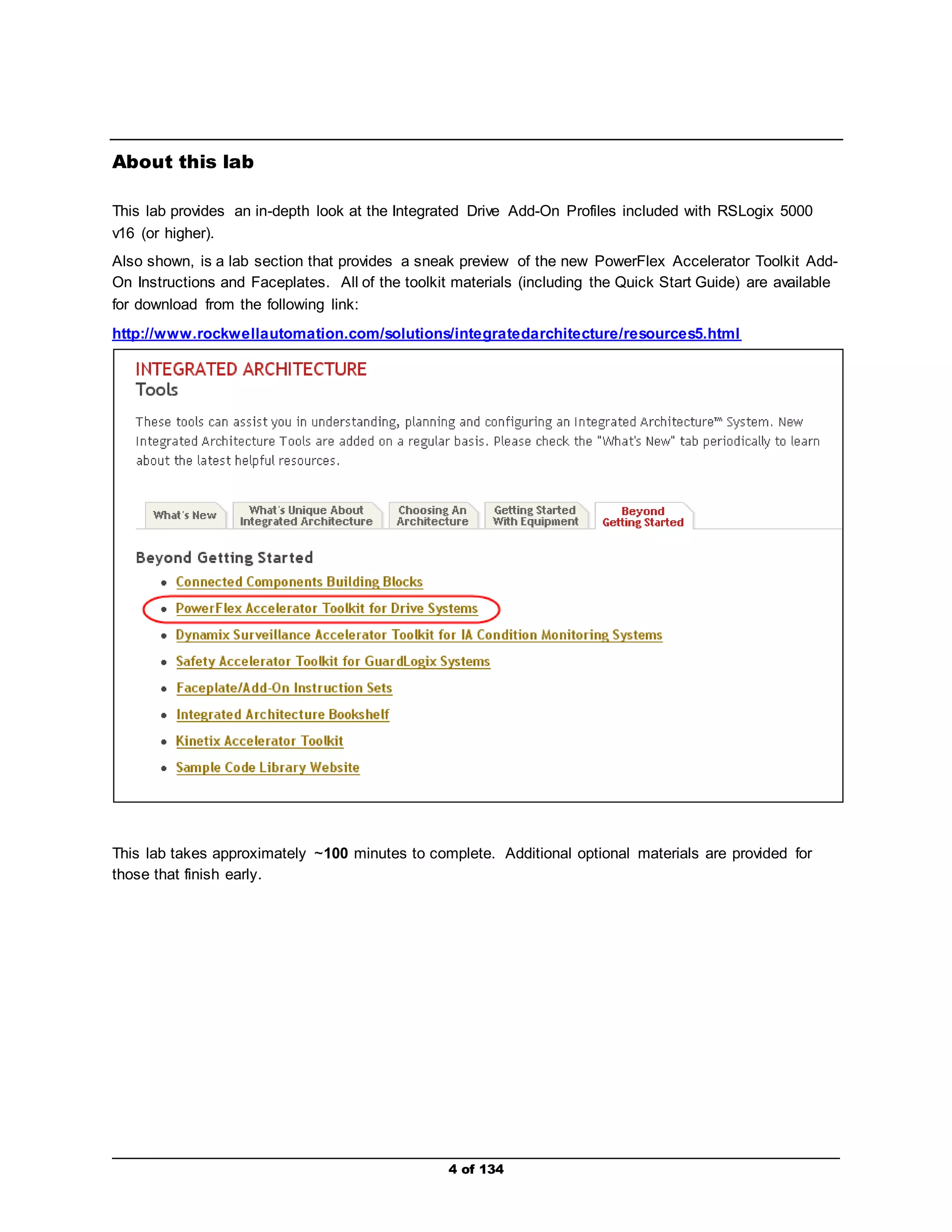
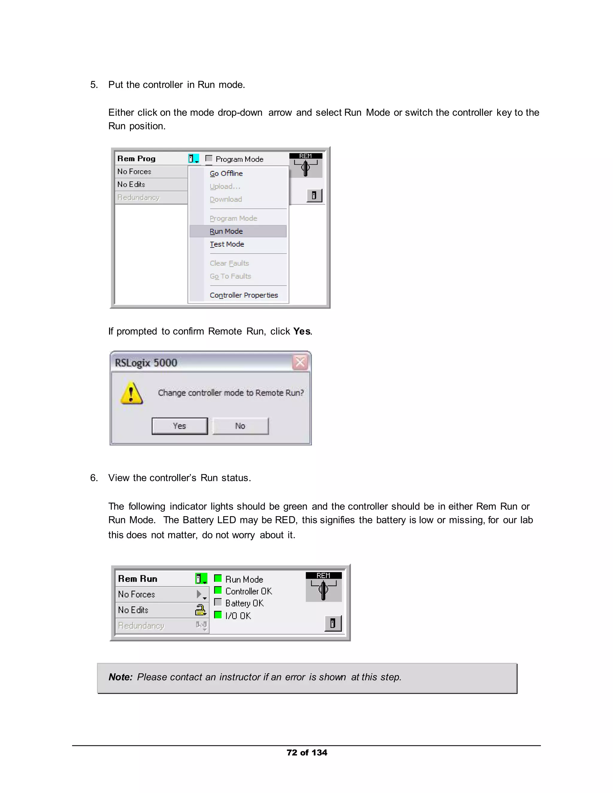
7. Control the drive.
a. Enter values for AccelTime1 and DecelTime1 in the column labeled Value. Note their
format is a float, so a value of 2.5 equates to 2.5 seconds.
b. Enter a value between 0 and 60.0 for the Reference. This is the speed reference in Hz
or RPM (represented as a float), depending on which units are selected. For the lab, Hz
was selected.
c. Enter a 1 for ClearFaults and then set it back to 0. This will reset any fault in the drive.
d. Enter a 1 for the Start and then set it back to a 0. All starts require a rising edge (0 to 1)
transition.
If desired, use the HIM to look at Parameter 535 [Accel Time 1] and
Parameter 537 [Decel Time 1] to verify that the data is being sent by the controller.](https://image.slidesharecdn.com/premierintegrationwithlogixpfdrivesandftviewpf755-140914194441-phpapp01/75/Premier-integration-with-logix-pf-drives-and-ft-view-pf755-74-2048.jpg)


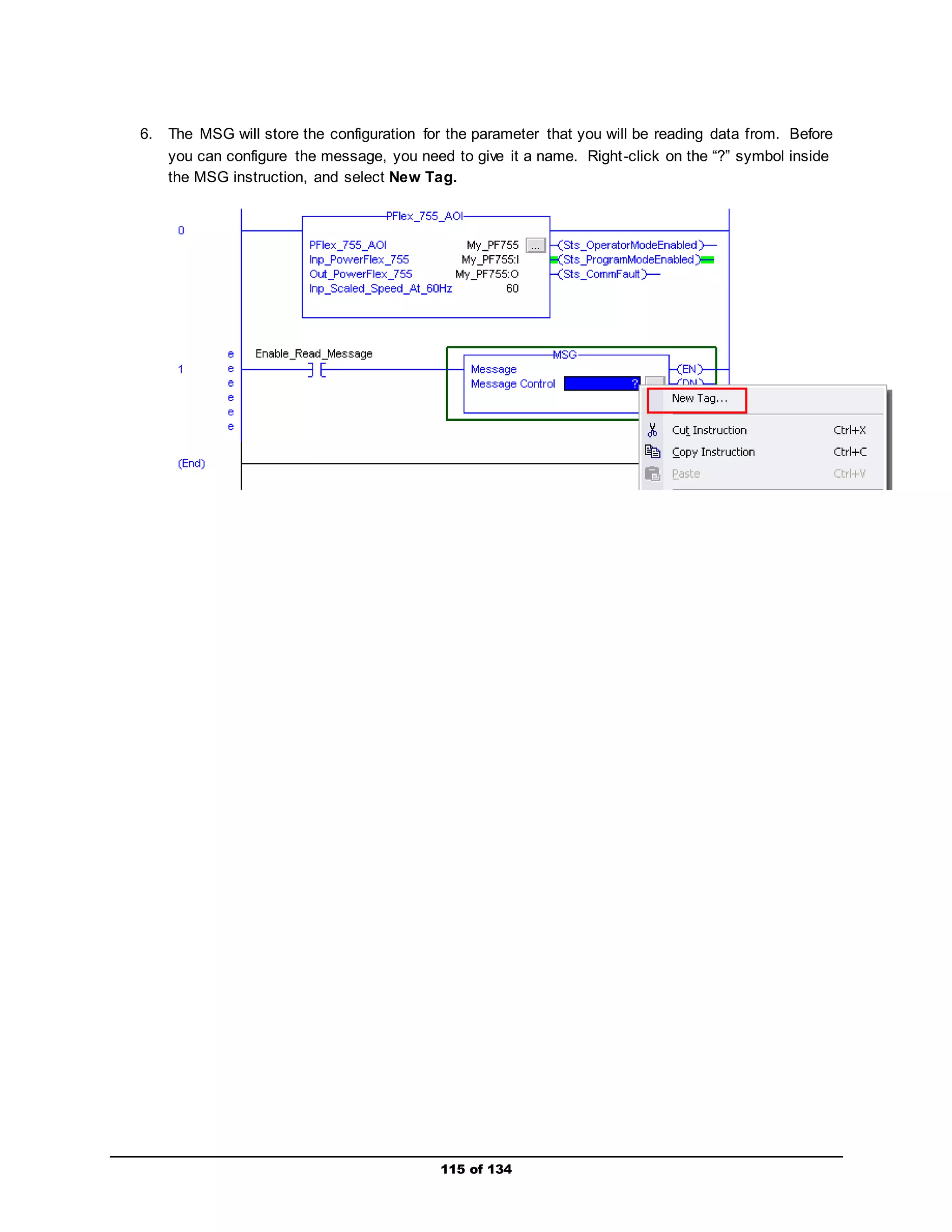
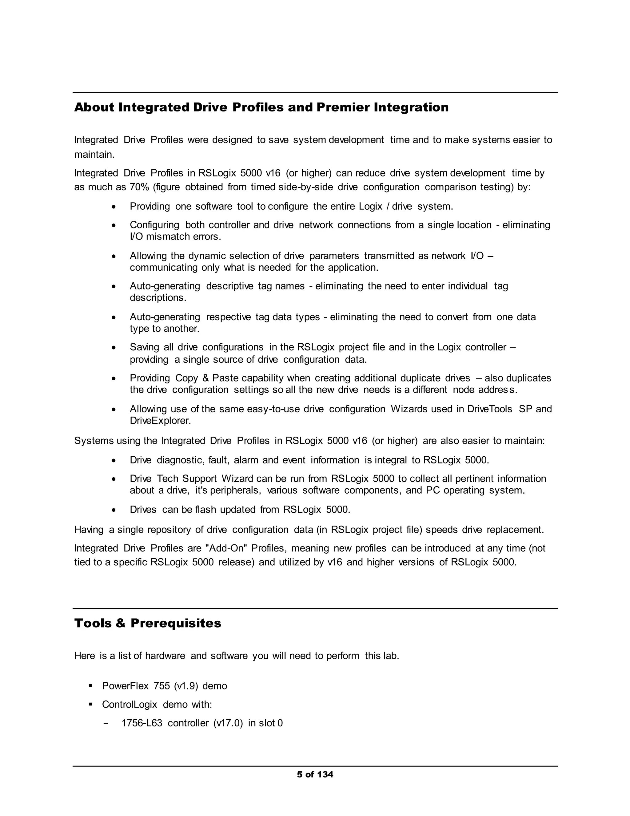
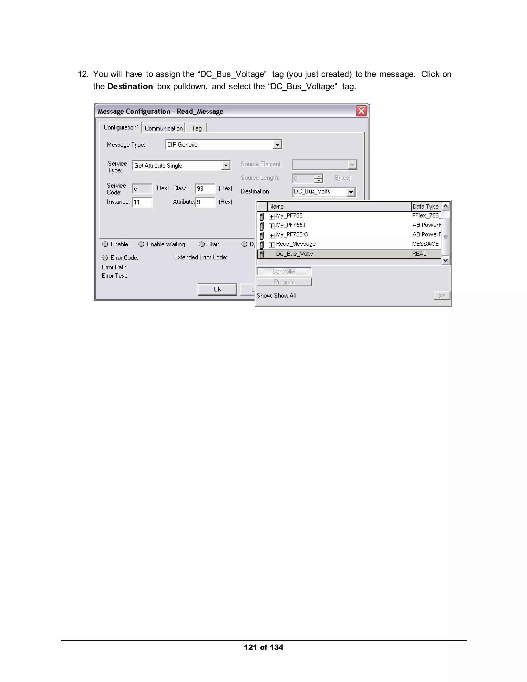
![11. All you have to do now is type in the parameter number that you want to read information from in
the Instance box and then create a Destination tag where the parameter information will be
stored.
For this example, we are going to read Parameter 11 [DC Bus Volts]. Therefore, in the Instance
box, type 11.
Next, you will have to create a tag that will represent parameter 11 and store its information.
Click on New Tag, type in “DC_Bus_Volts” in the Name box, set the Data Type to “REAL”, verify
the Scope field is set to “My_Controller,” and then click OK.
120 of 134](https://image.slidesharecdn.com/premierintegrationwithlogixpfdrivesandftviewpf755-140914194441-phpapp01/75/Premier-integration-with-logix-pf-drives-and-ft-view-pf755-120-2048.jpg)
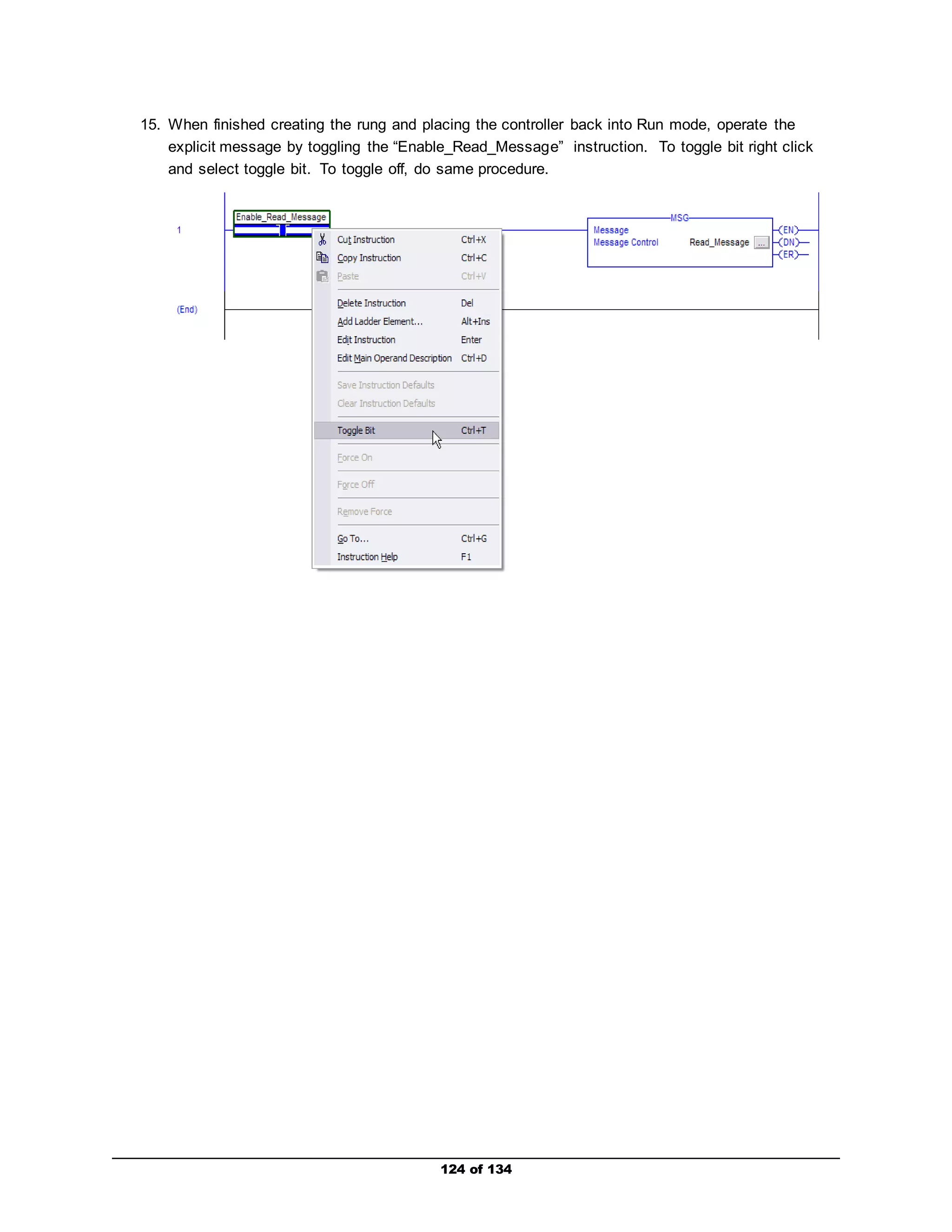
![The MSG instruction should set its EN bit and then its DN bit if the explicit message was
successful. Re-toggle the “Enable_Read_Message” instruction again to reset the MSG
instruction.
If the ER bit is set, an error in the explicit message has occurred. In this case, verify that the
explicit messaging configuration information is correct. Toggle the “Enable_Read_Message”
instruction again, and verify that the MSG instruction set its EN bit and then its DN bit.
Go into the Controller Tags folder, and verify a value range between “300 - 350” appears in the
“DC_Bus_Volts” tag. This parameter is a real value, so scaling is not required. Also, since the
drive’s input voltage is 230/240 VAC, the DC equivalent would be approximately 300 - 350 VDC.
If you are still having trouble, please call over an instructor.
Repeat Steps 3 through 15 for an explicit message Write that will write information to
Parameter 536 [Accel Time 2]. Use the following values to the complete the message write.
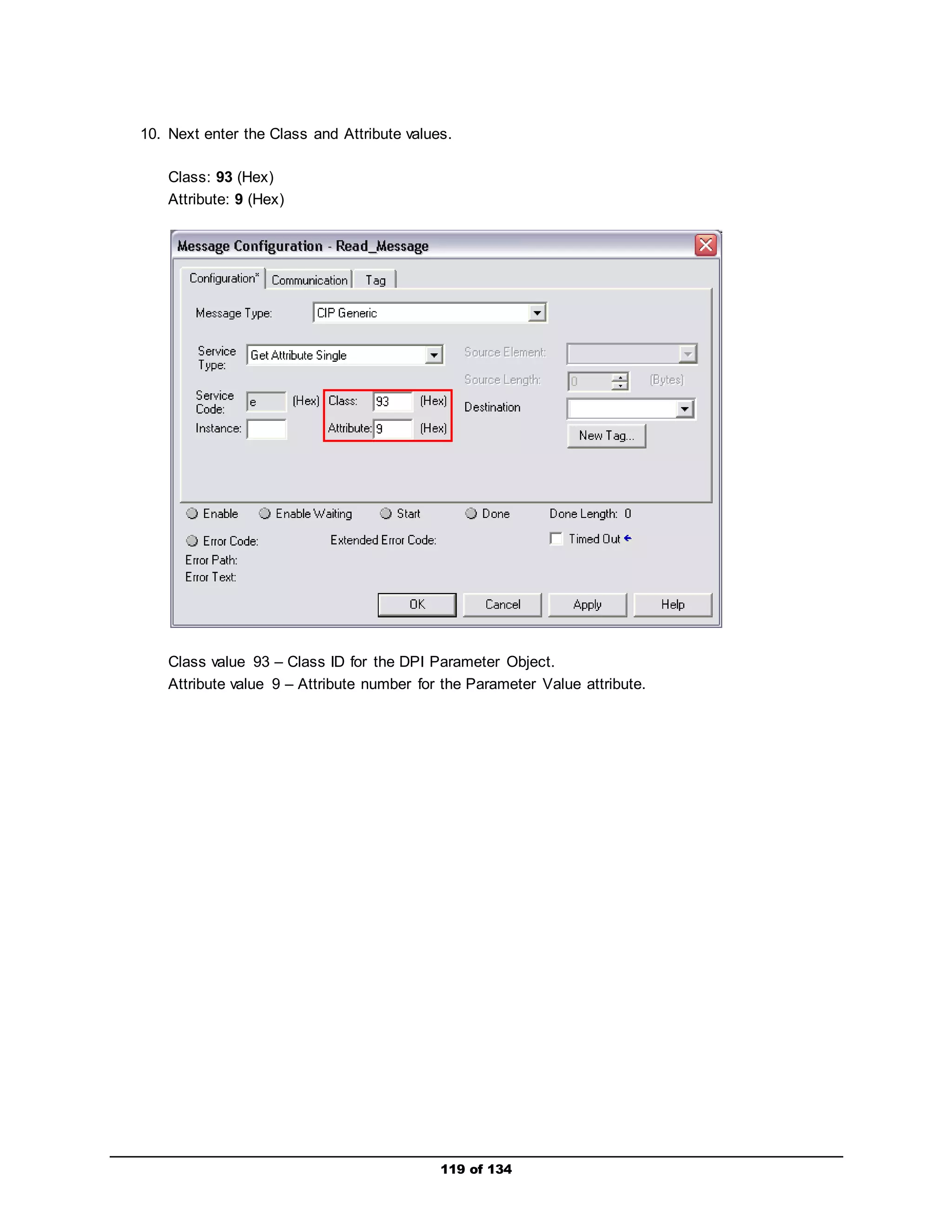
Message Type: CIP Generic
Service Type: Set Attribute Single
Class: 93 (Hex)
Instance: 536 (Dec)
Attribute: 9 or A (Hex)
Source Element: Accel_Time_2 (Data Type – REAL)
Source Length: 4 bytes
When you are finished, you may show your instructor. If you are having trouble getting started,
please ask an instructor for assistance.
125 of 134](https://image.slidesharecdn.com/premierintegrationwithlogixpfdrivesandftviewpf755-140914194441-phpapp01/75/Premier-integration-with-logix-pf-drives-and-ft-view-pf755-125-2048.jpg)

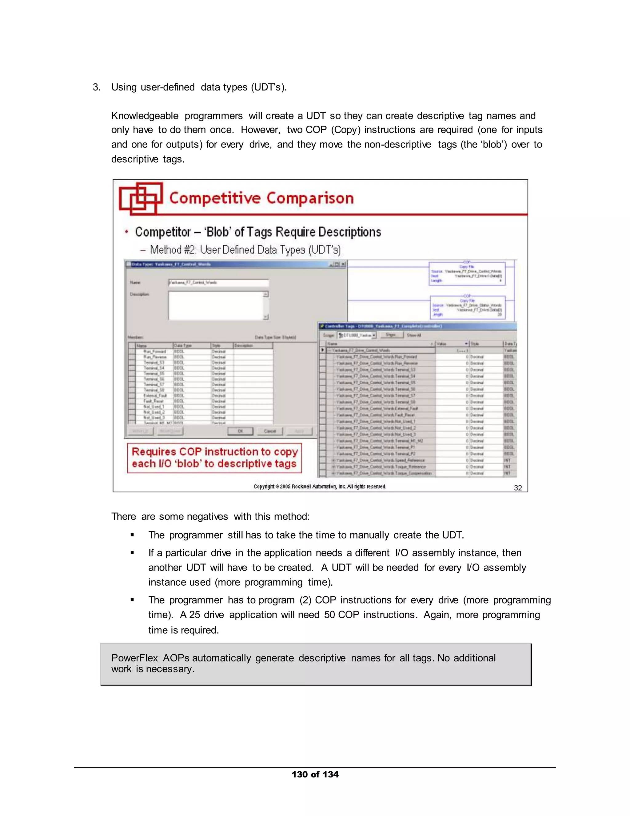
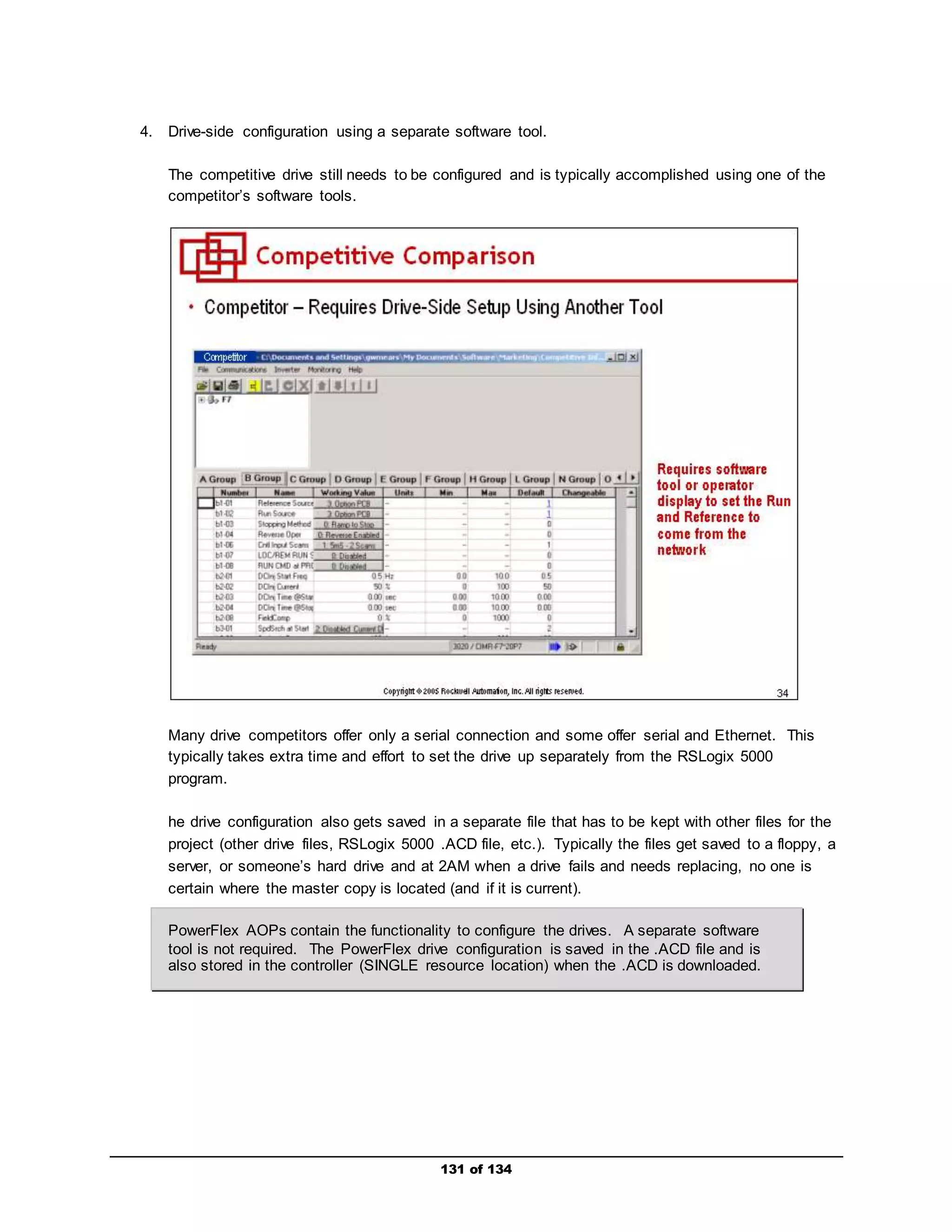
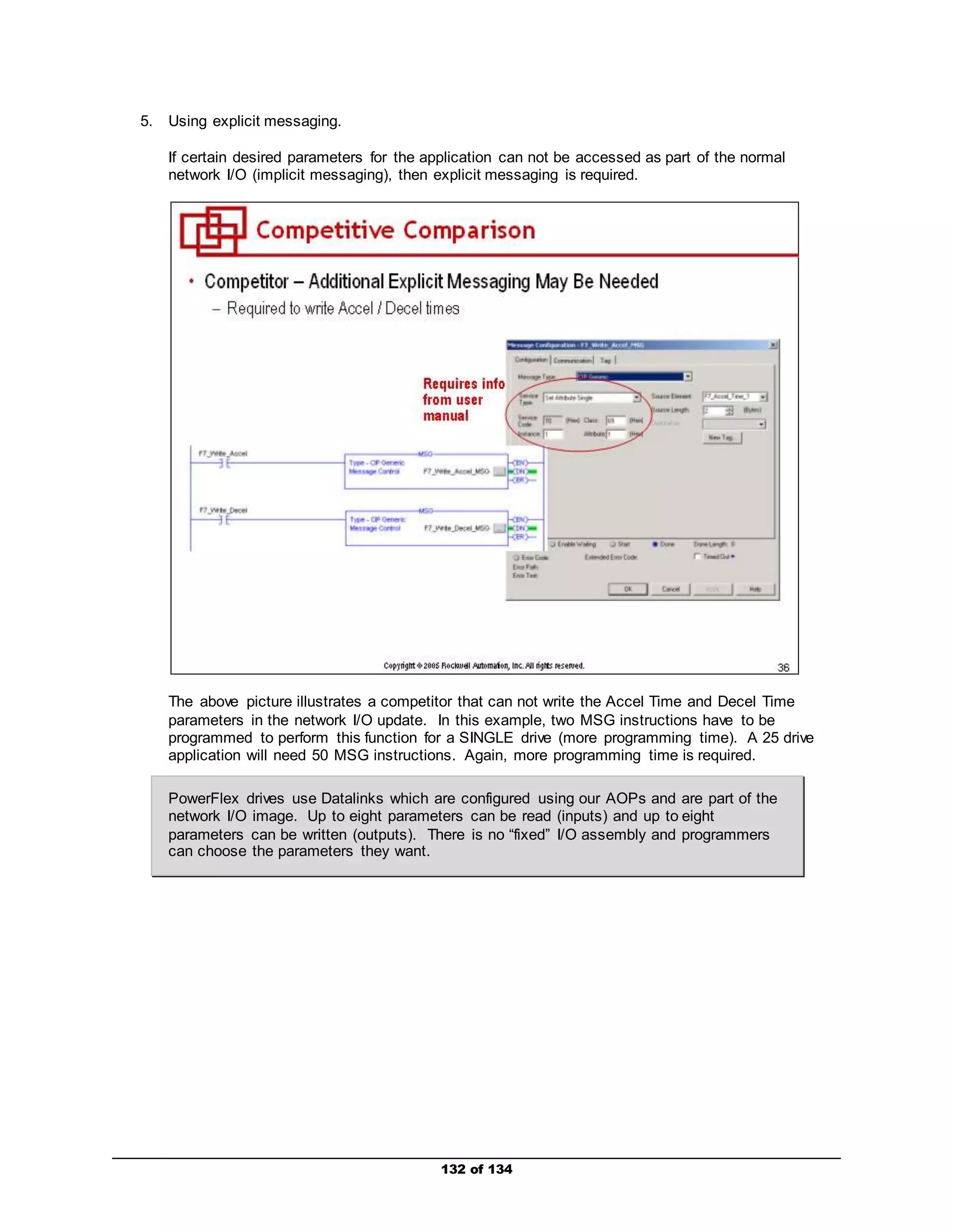
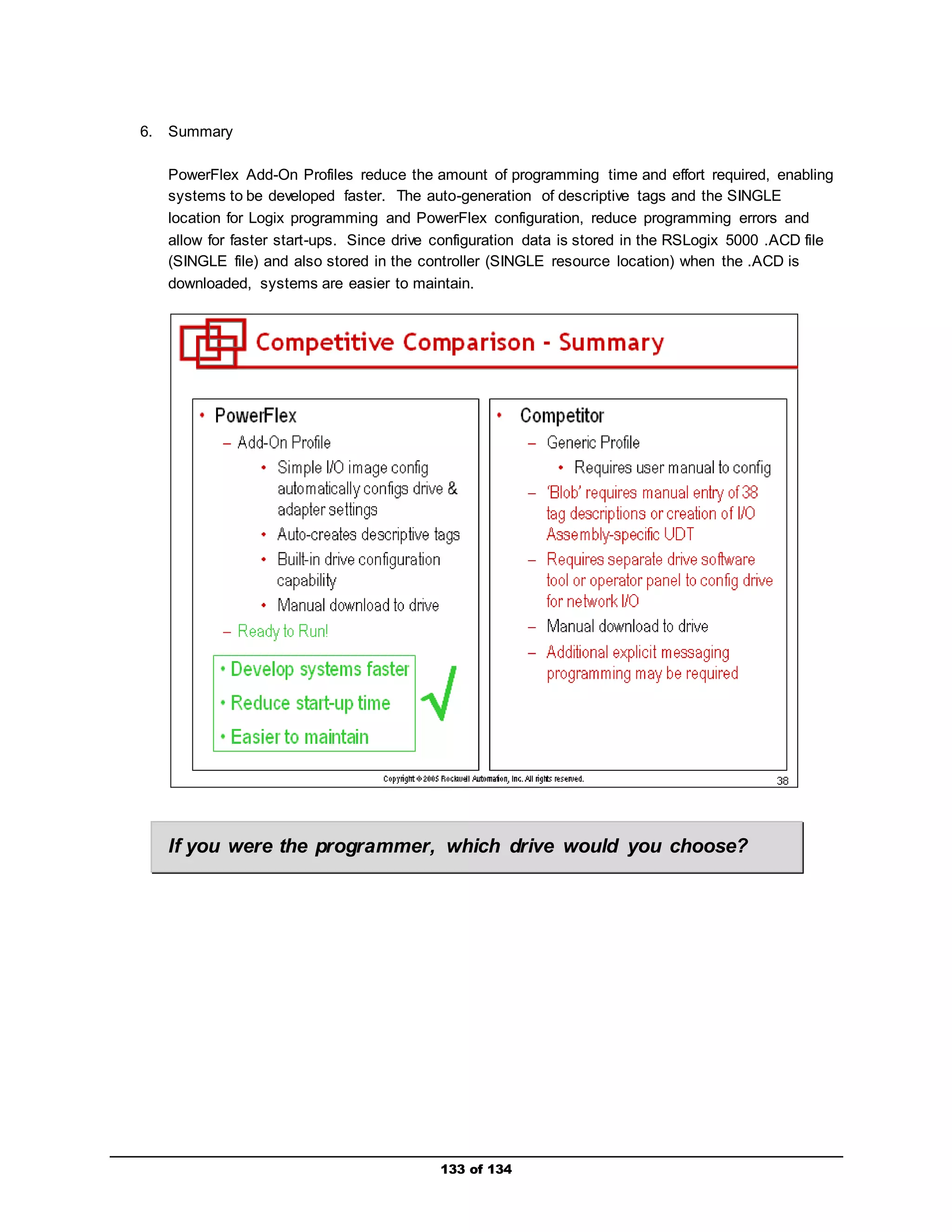


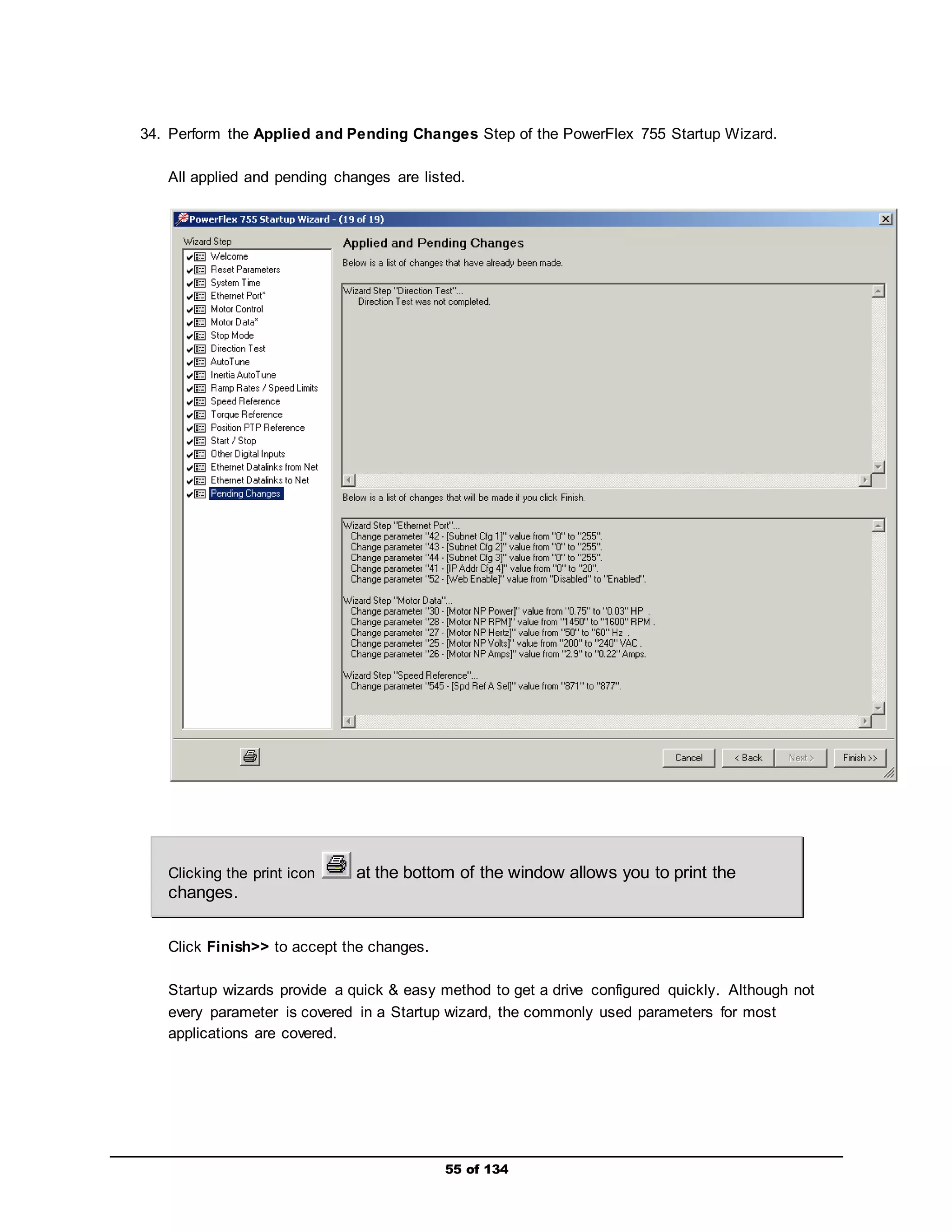
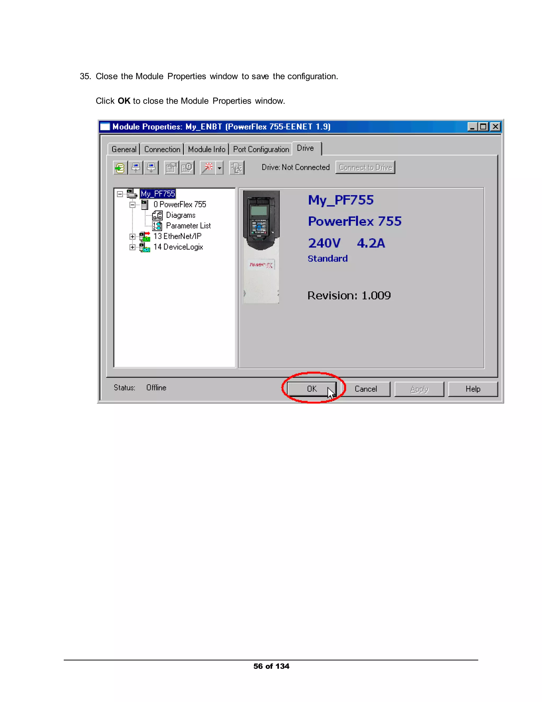
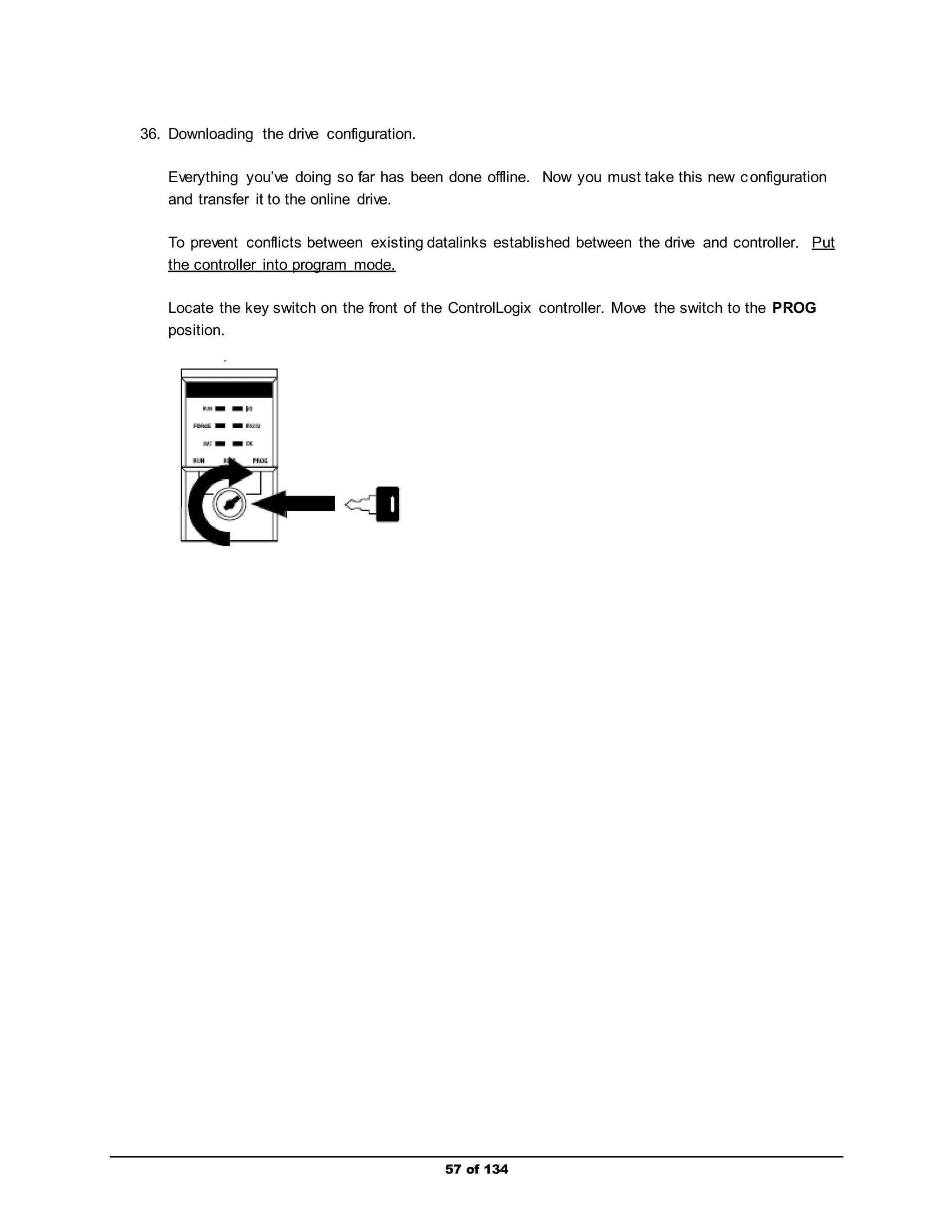
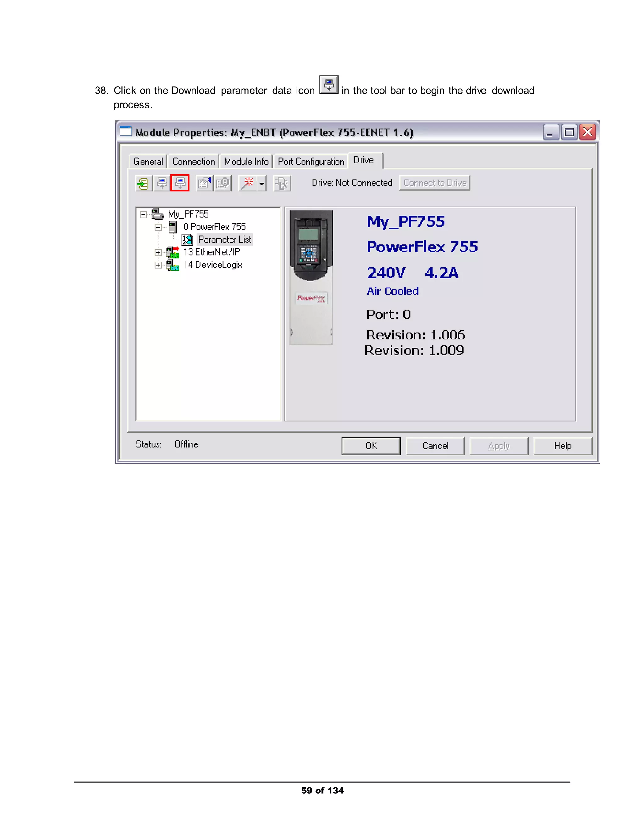
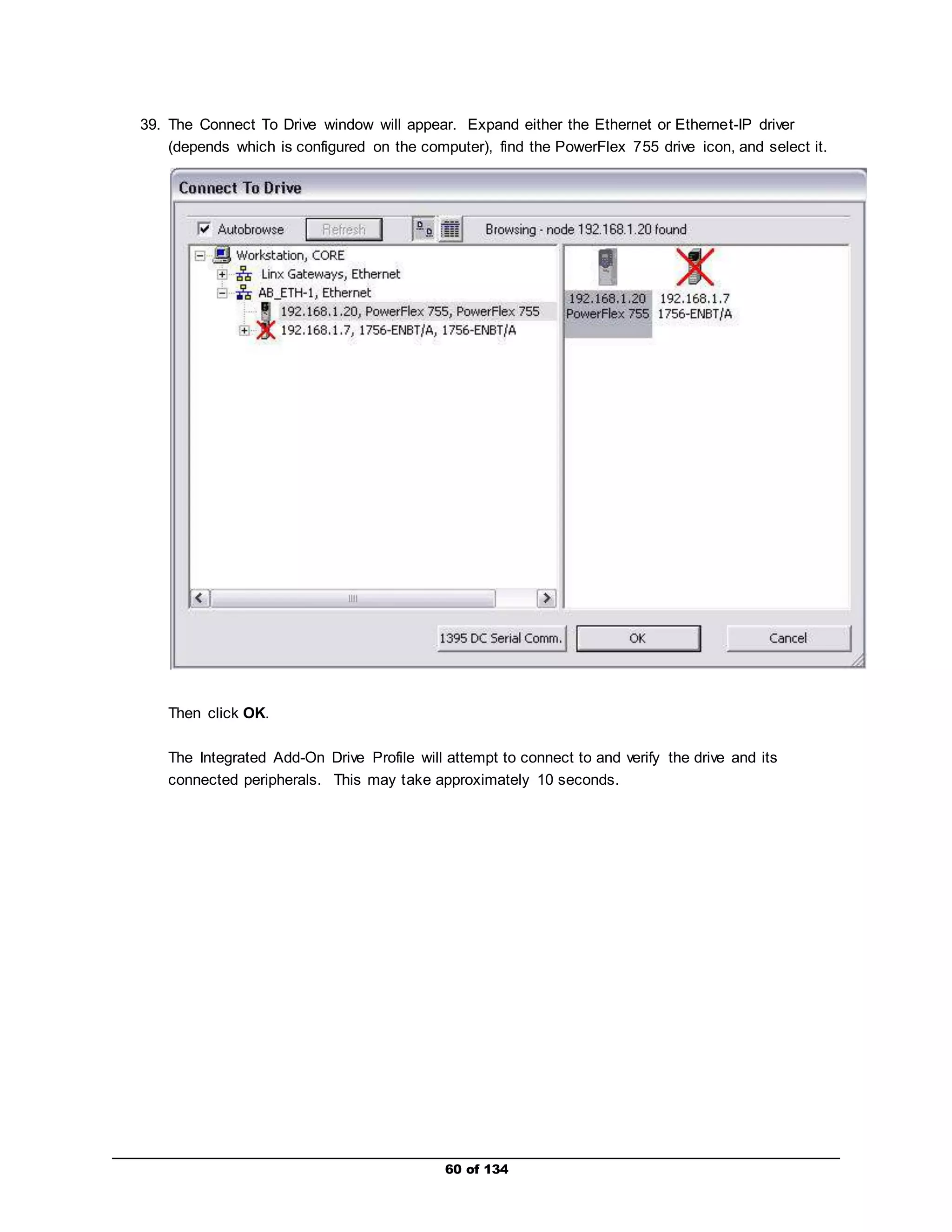
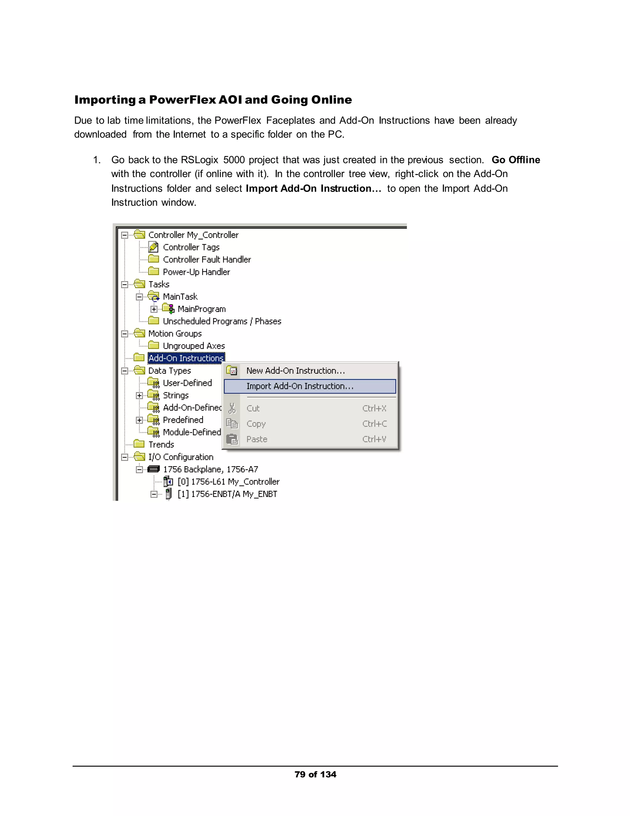
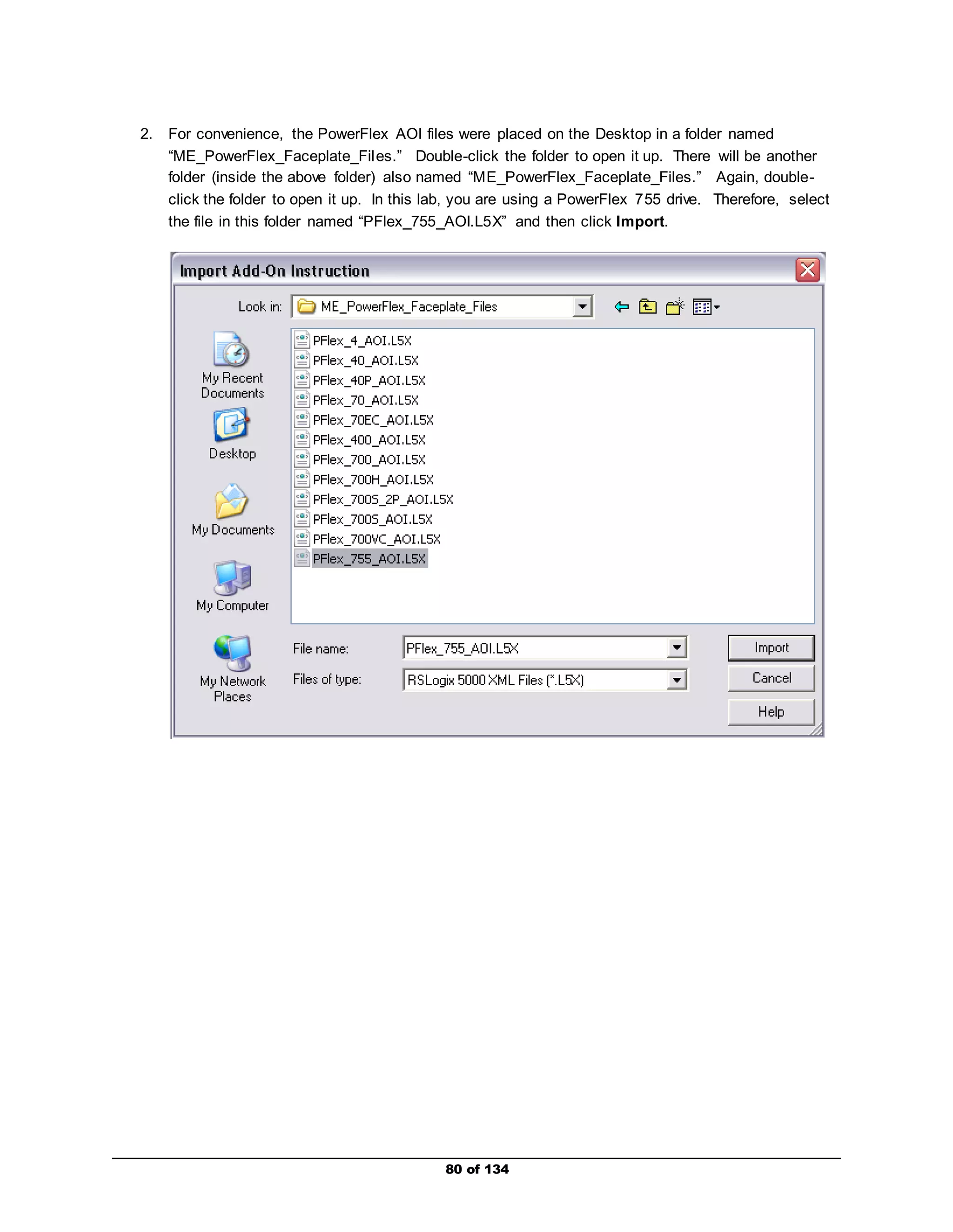
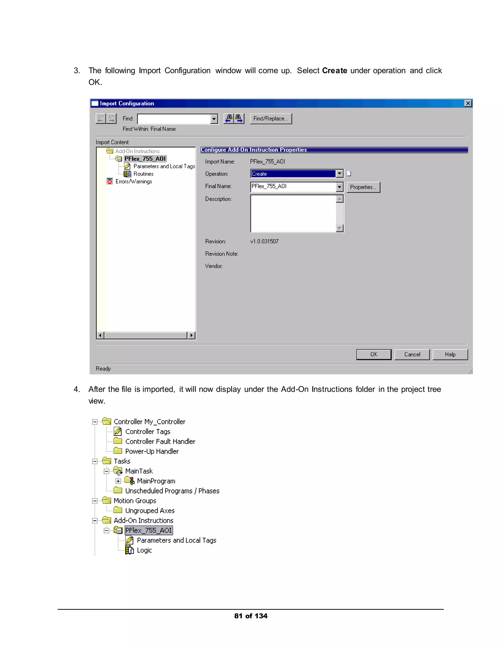
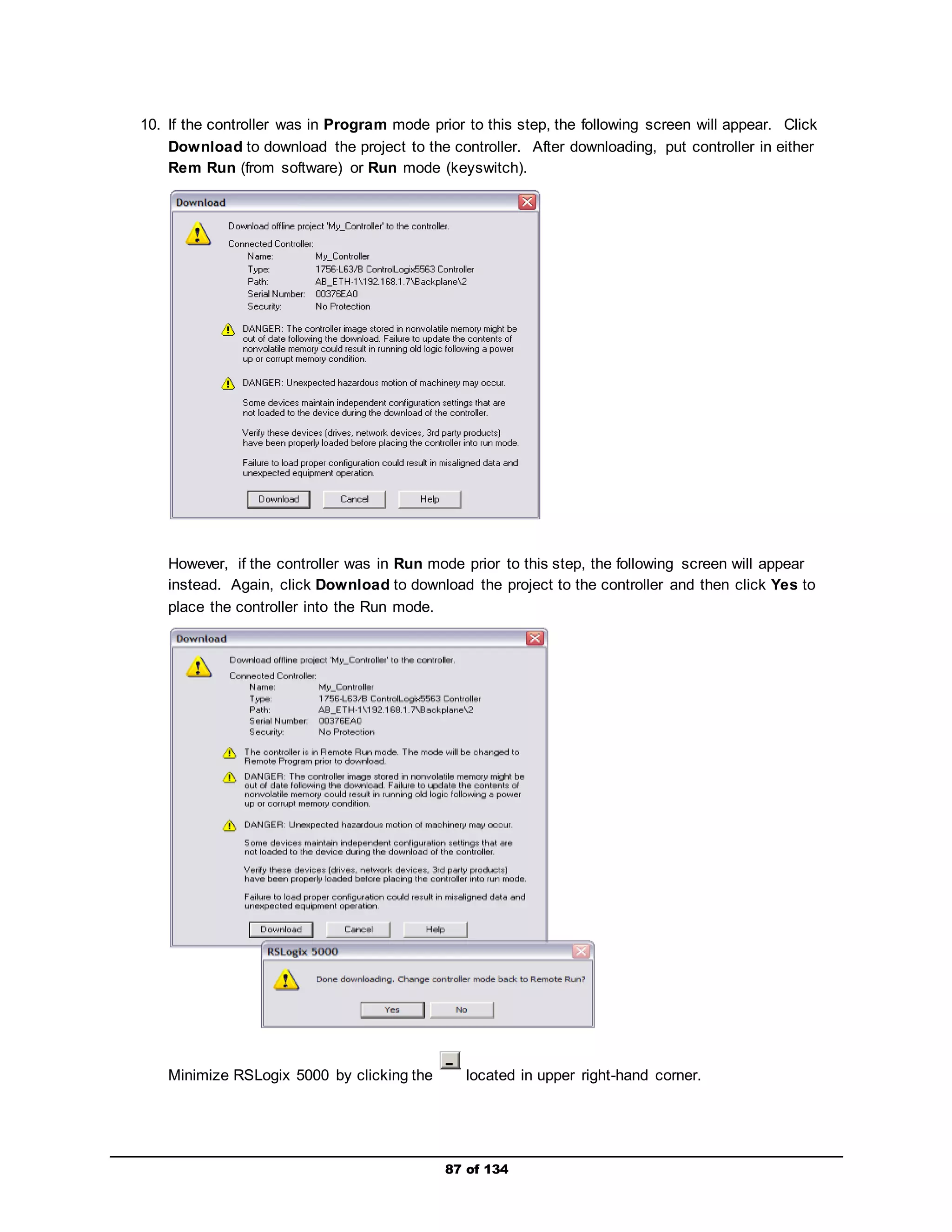
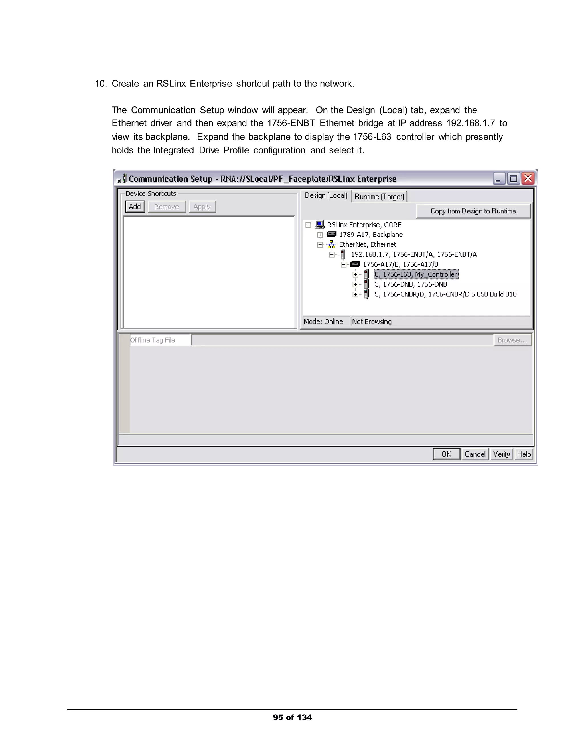
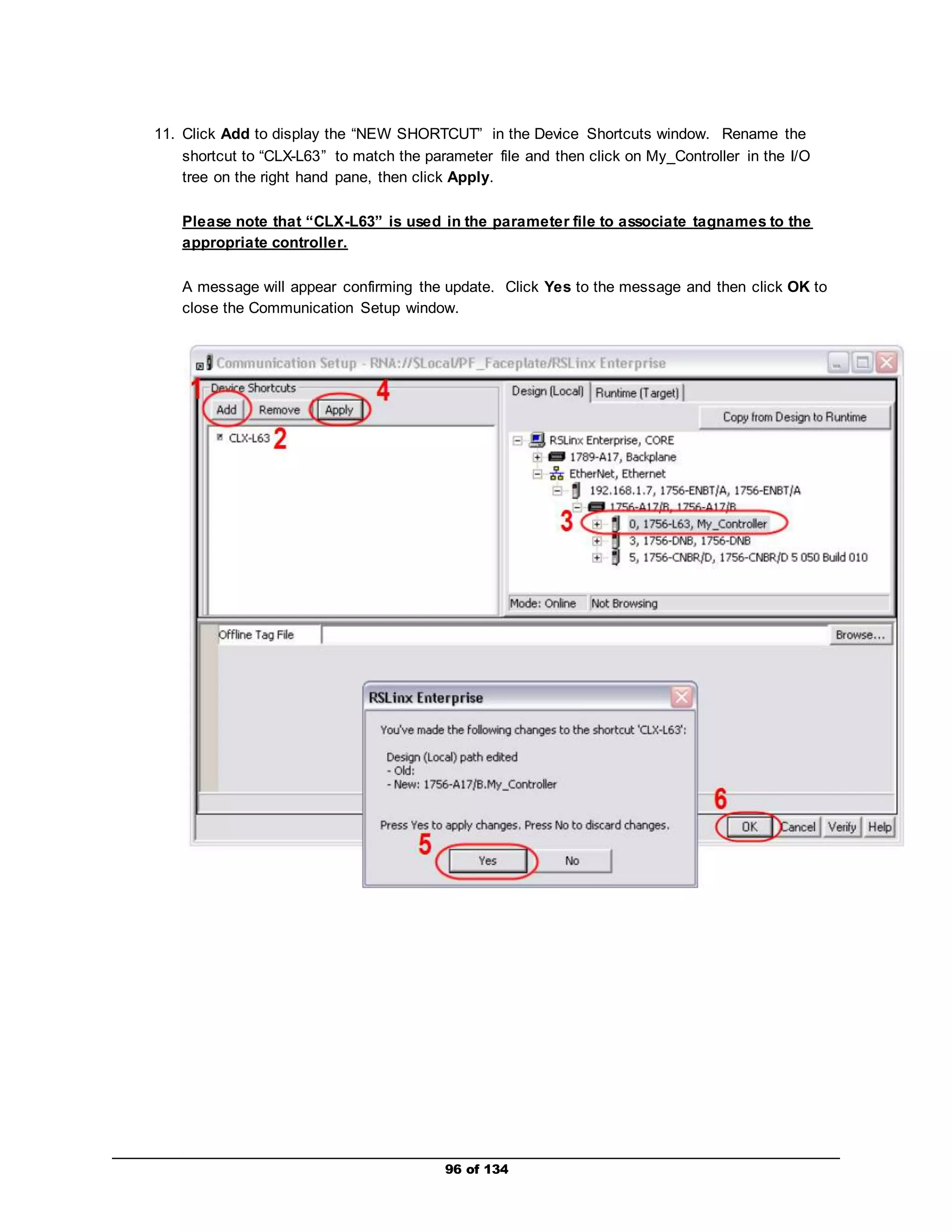
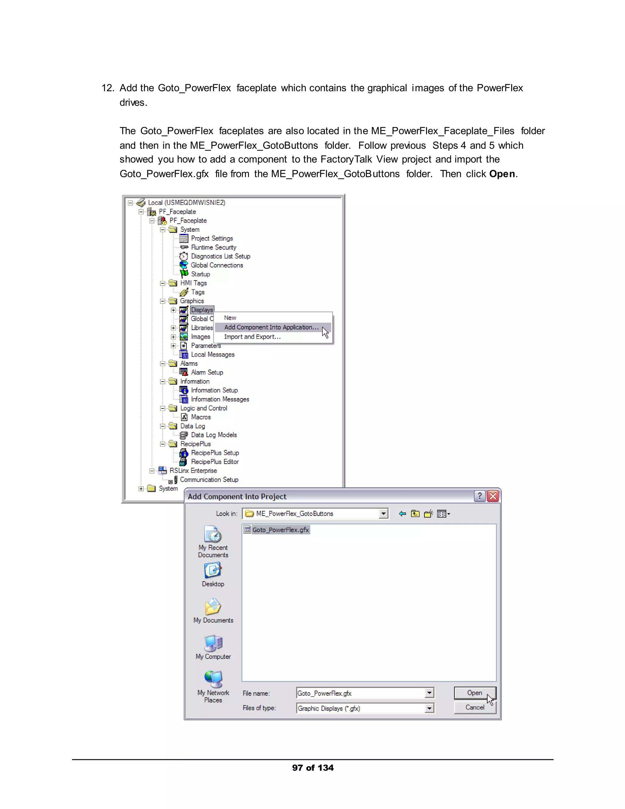
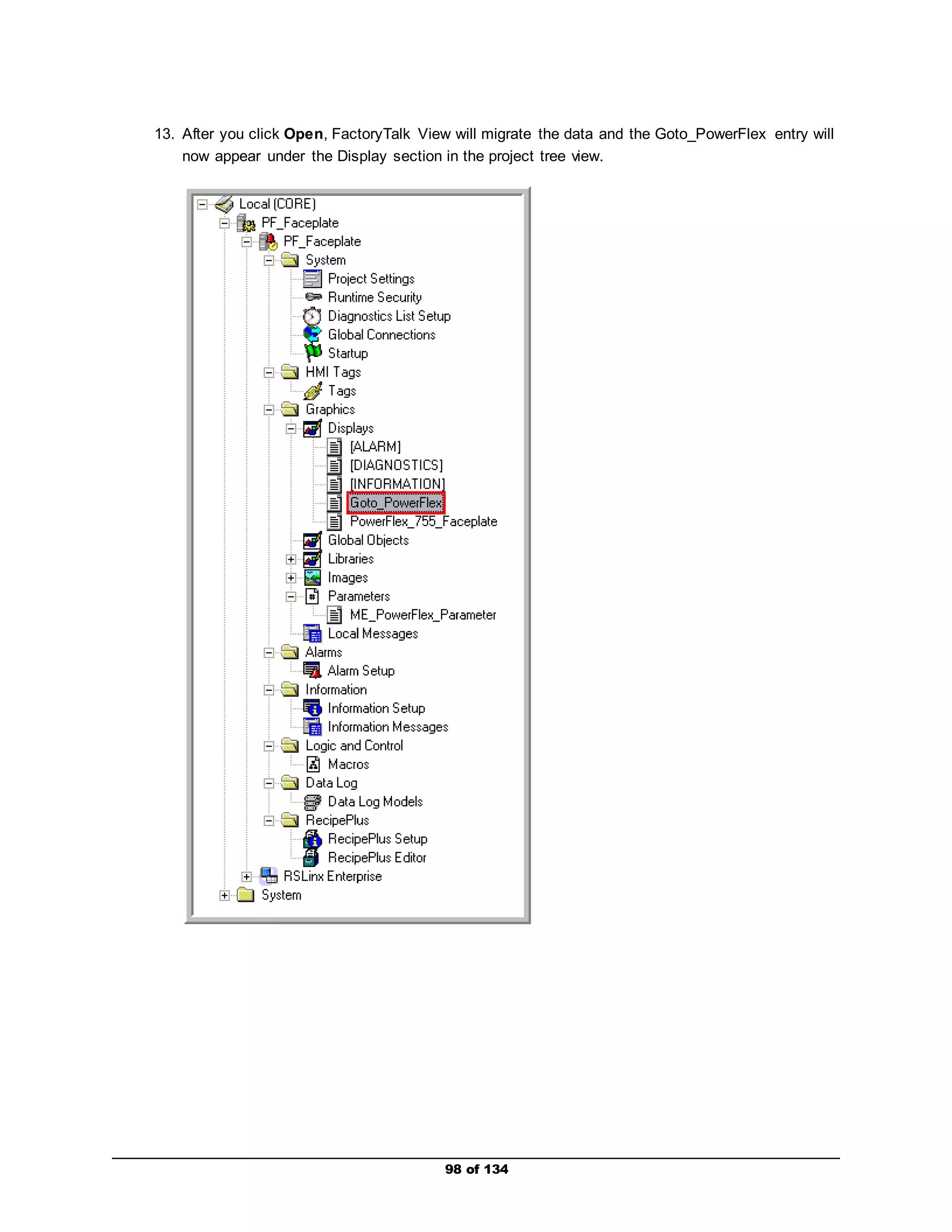
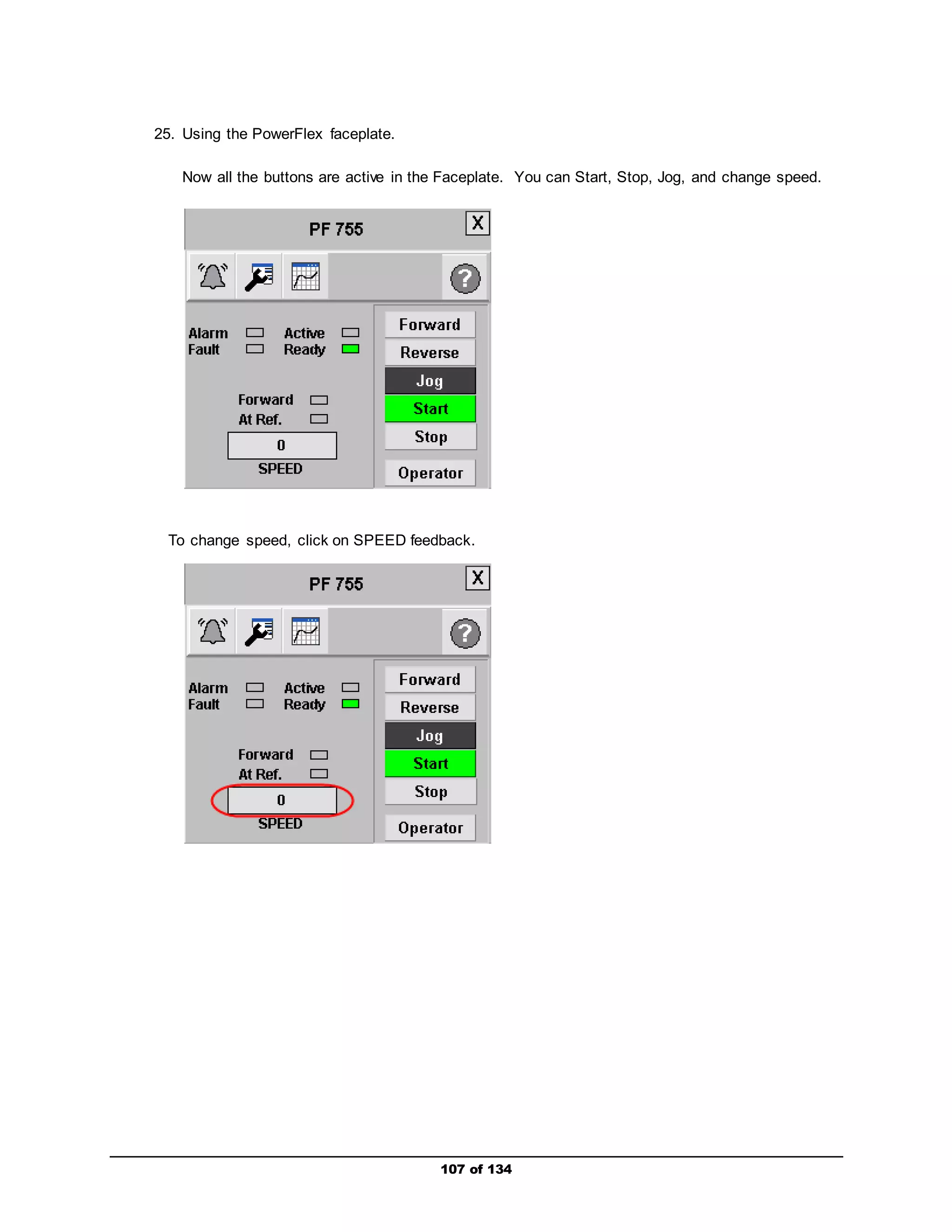
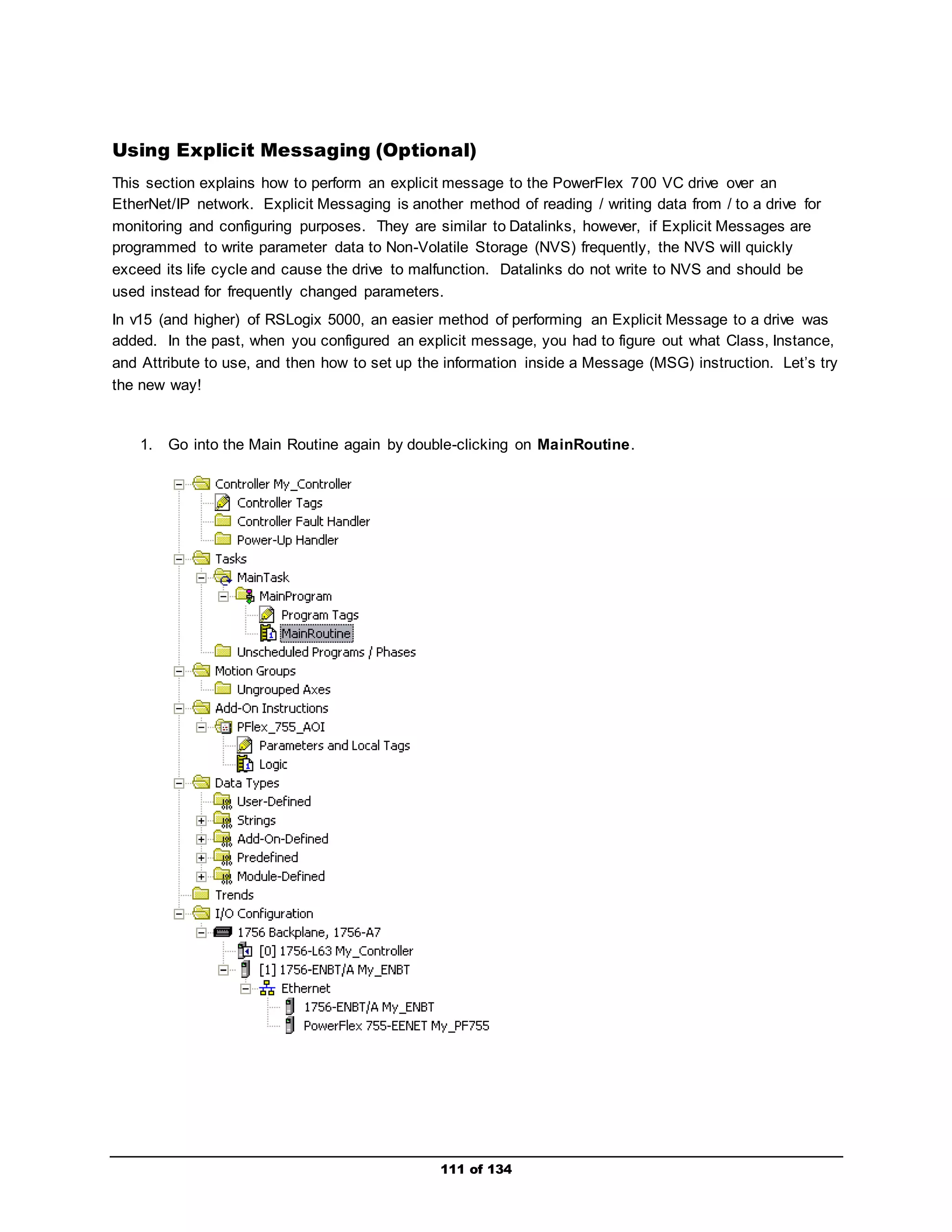
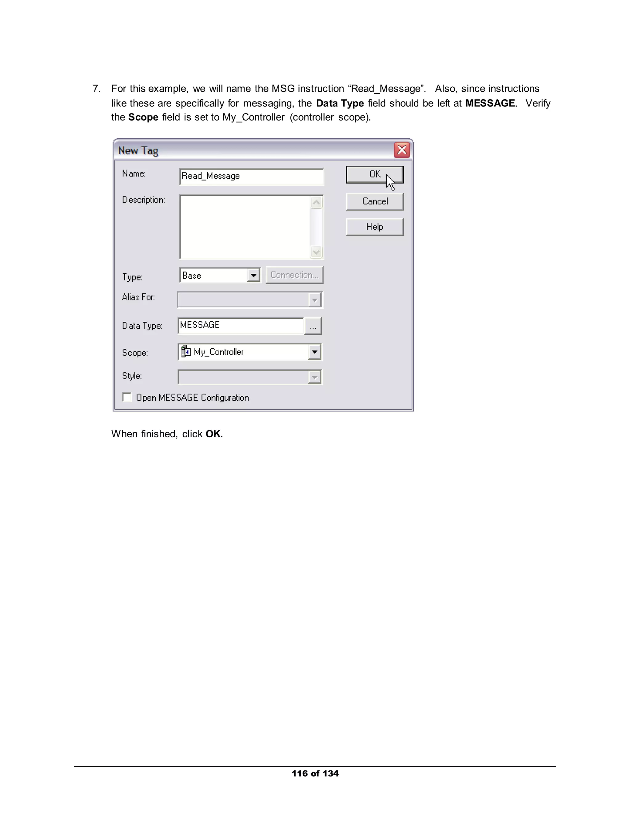
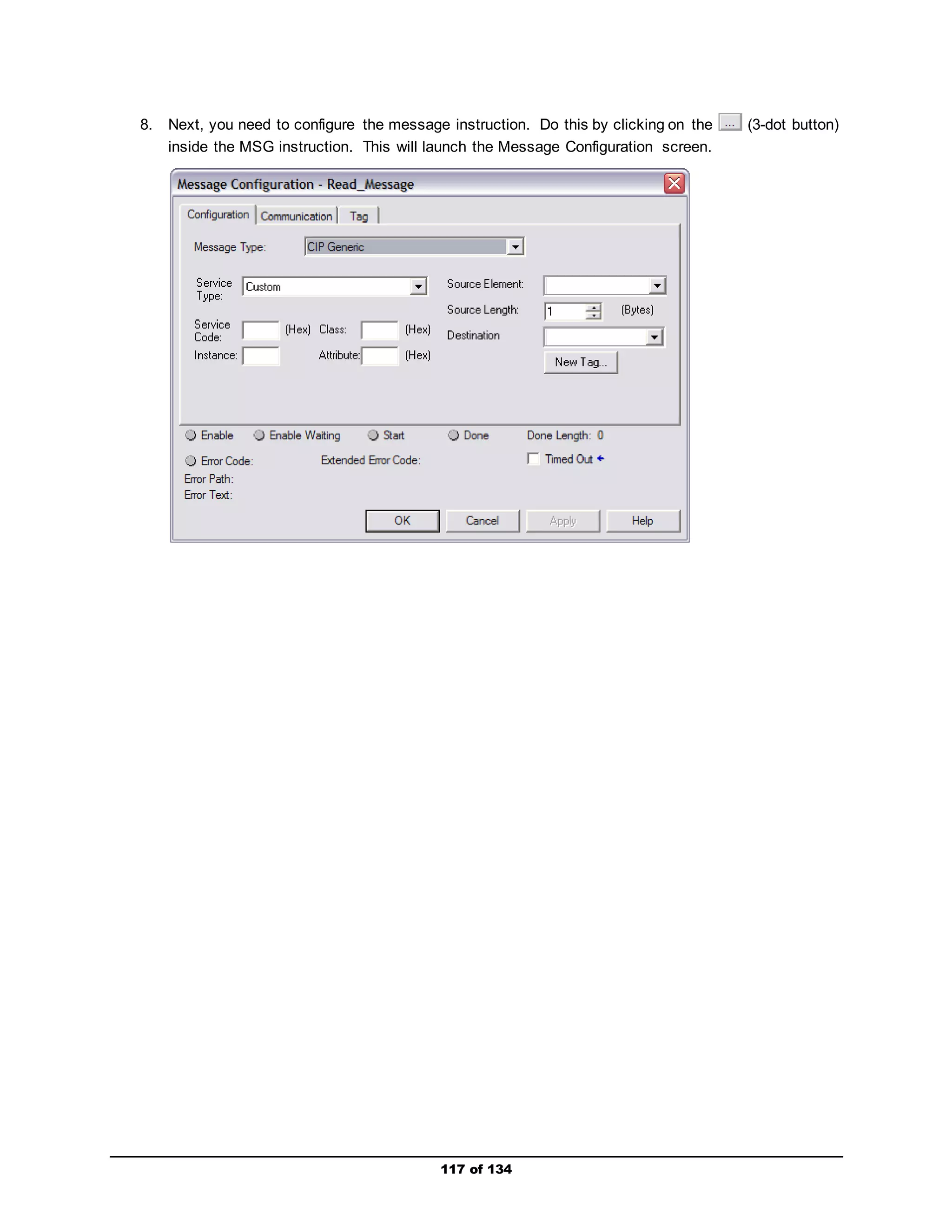
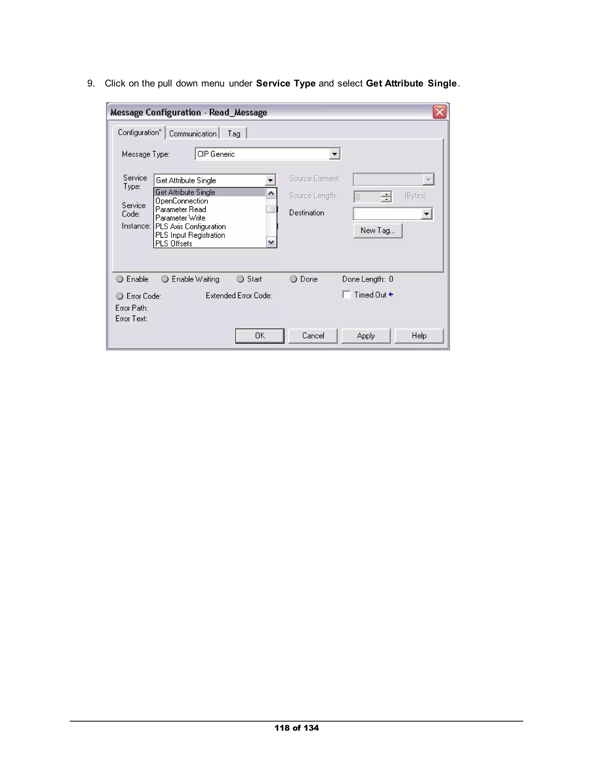
This document provides instructions for a lab that demonstrates integrating a PowerFlex 755 drive with a ControlLogix controller using RSLogix 5000 software. The lab includes steps for connecting hardware, creating an RSLogix 5000 project with an integrated drive profile for the PowerFlex 755, configuring network I/O between the devices, and using FactoryTalk View ME to monitor and control the drive. Optional sections provide additional exercises for explicit messaging, viewing drive web pages, a conveyor application example, and using a non-AB drive.


