Downloaded 164 times
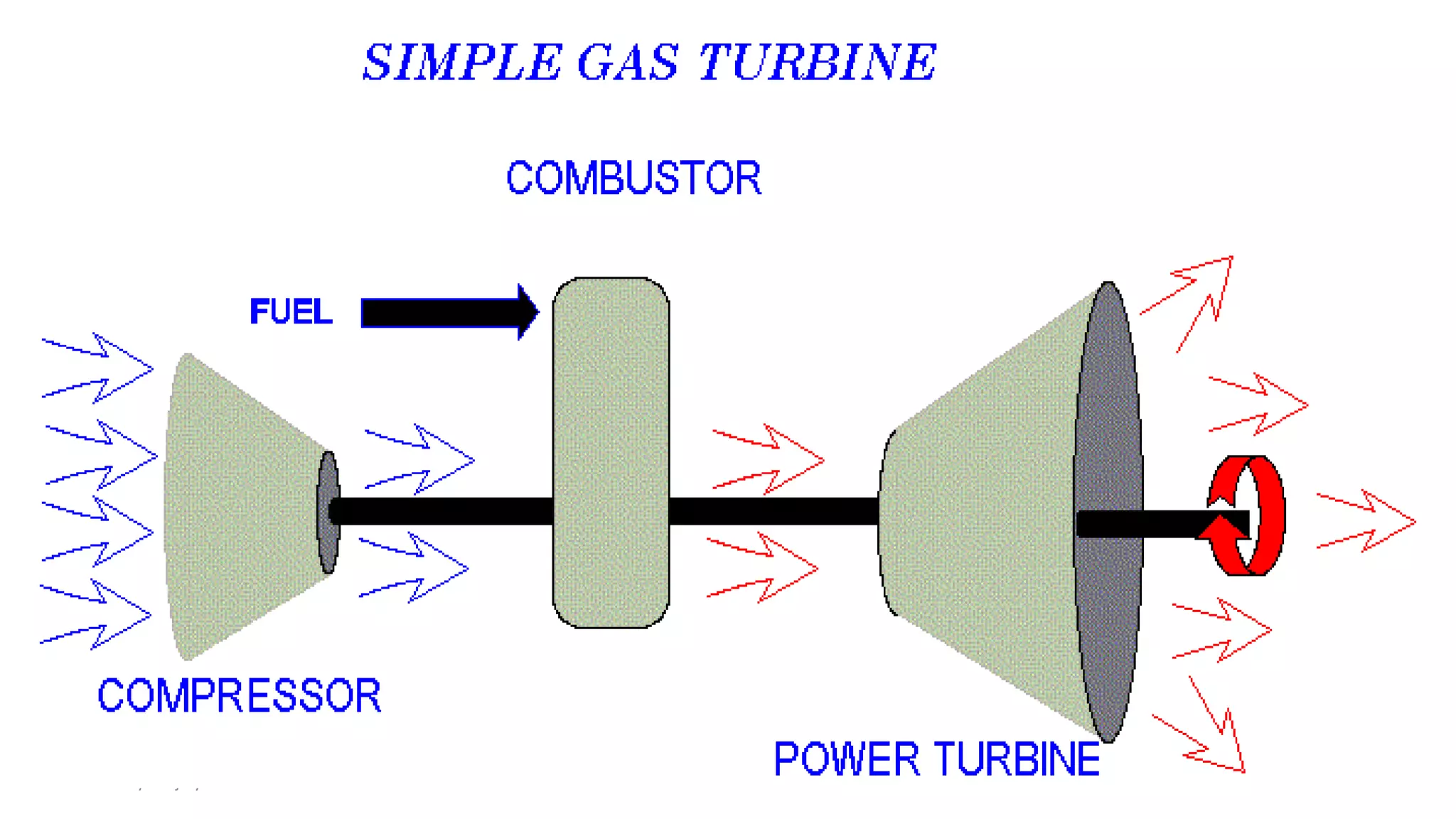
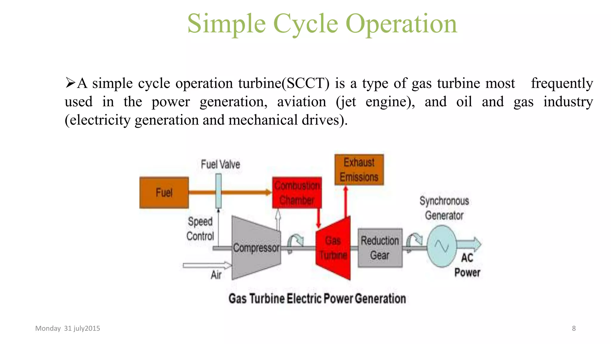


The presentation provides an overview of the NTPC Anta gas power plant in Rajasthan, India. It discusses the gas turbine process which involves compressing air, combusting it with fuel, and expanding the combustion products through a turbine. The plant uses natural gas as its primary fuel. It has a total installed capacity of 419.33 MW from 3 gas turbine units and 1 steam turbine unit in a combined cycle configuration. Measurements of processes like pressure, temperature, flow and electrical parameters are crucial to operations. Power is evacuated from the plant using six 220kV transmission lines.


