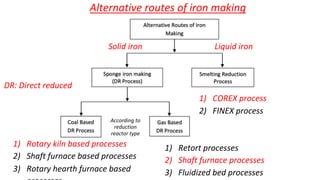
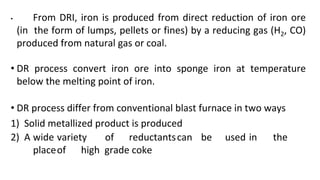
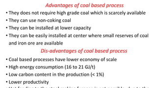
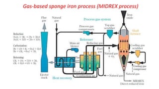
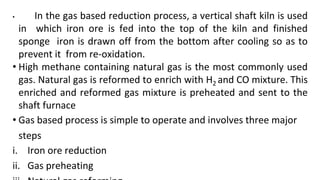
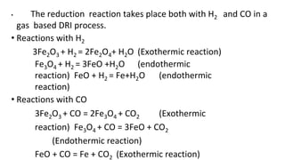
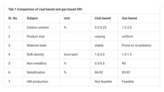
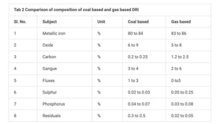
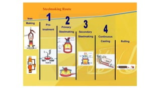
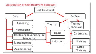
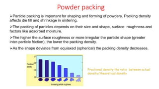
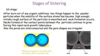
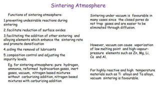
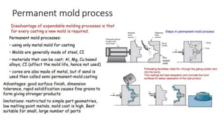
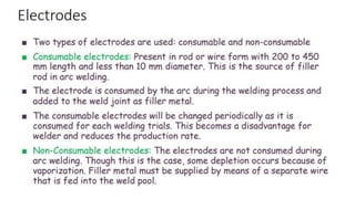
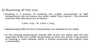
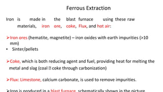
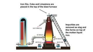
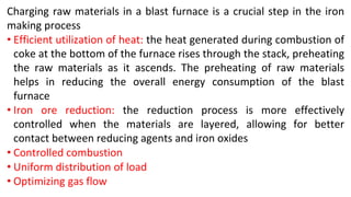
The document outlines the metallurgical engineering course evaluation policy and delves into the global steel production statistics, including India and Asia's contributions. It explains the iron extraction process in a blast furnace, detailing raw materials, reactions, and the roles of coke and flux in producing molten iron and slag. Additionally, the document highlights alternative iron-making methods, including coal-based and gas-based processes, and their advantages and disadvantages compared to conventional methods.

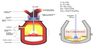
![SiO2 + C 🡪 SiO + CO
SiO2 + 3C 🡪 SiC + 2CO
SiO+ 2C
SiO + [C] 🡪 [Si] +CO
2SiO 🡪 SiO2 + [Si]
FeO + SiO 🡪 [Fe] +SiO2
How to decrease the Si in the hot metal?
High blast pressure
Silicon
(Si)
CO
[] 🡪 dissolved state
Le Chatelier’s principle](https://image.slidesharecdn.com/metallurgicalengineeringppt-240728164703-c5fda394/85/ppt-on-Metallurgical-Engineering-PPT-pptx-22-320.jpg)