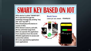
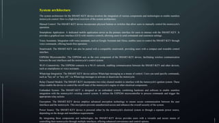
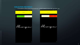
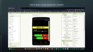
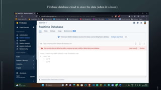
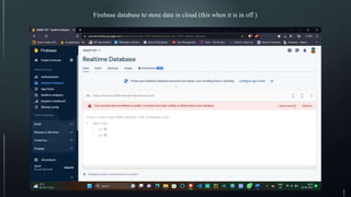
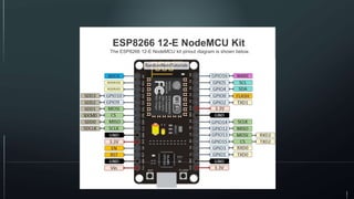
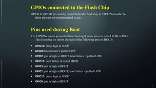
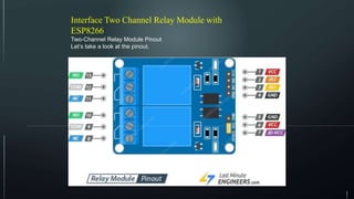
This device is called the SMART-KEY and is used to remotely control a motorcycle through multiple interfaces like a mobile application, WhatsApp messages, voice assistants, and smartwatches. It uses an ESP8266 microcontroller connected to two relay channels to interface with the motorcycle's ignition system and enable on/off control of the engine or other electrical components remotely. The SMART-KEY device employs encryption and integrates components like the ESP8266, relays, and interfaces with platforms like Firebase and ThingESP to provide a secure and customizable way to remotely control a motorcycle.
The prime concern of this project is to develop a system that is more friendly for all but especially blind, elderly(senile) people so that they can use it with more ease as it is self-controlled. It will also reduce human efforts to great extent. It is used for maximizing user’s comfort offering an easy way to personalize home.
Home automation-in-the-cloud-with-the-esp8266-and-adafruit-ioTran Minh Nhut
The document describes building a home automation system using ESP8266 WiFi modules and Adafruit IO cloud service. It involves creating two modules - a sensor module to measure temperature and humidity using a DHT sensor, and a lamp controller module to control a lamp. The modules are programmed using Arduino IDE and code from a GitHub repository. They connect to Adafruit IO to send sensor readings and receive commands to control the lamp remotely over the internet.
This document describes a home automation project using an Arduino Uno and Bluetooth module. The circuit diagram shows how the Bluetooth module connects to the Arduino via TX and RX pins. An app is used to control four loads by sending codes to the Bluetooth module and Arduino code switches the loads on or off depending on the received code. The project automatically controls appliances but has limitations around continuous power. It could also be expanded to incorporate sensors for smart home automation and internet connectivity for remote control.
This document describes a voice-controlled smart home automation system using Google Assistant. NodeMCU (ESP8266) is used to control relays connected to home appliances like lights and fans. IFTTT connects the Google Assistant to the NodeMCU to allow voice commands to turn appliances on and off. Sensors like a gas detector and temperature sensor monitor the home for safety. The system provides convenience for elderly or disabled people to control their home using voice commands through Google Assistant.
The document discusses Internet of Things (IoT) and how to implement a basic IoT system using an ESP8266 microcontroller. IoT refers to connecting physical devices to the internet. An ESP8266 allows connecting sensors like a DHT11 temperature/humidity sensor and an MQ-2 smoke sensor to WiFi. The Arduino IDE is used to program the ESP8266. Code is provided to read from the sensors and transmit temperature, humidity, and smoke detection data over serial. When implemented, this basic IoT system could detect and report on environmental conditions from a remote location.
The document discusses getting started with the Intel Galileo Gen 2 development board. It provides an overview of the board's specifications and input/output pins. It also describes how to set up the Arduino development environment and install the necessary drivers to use the board. Finally, it gives examples of simple Arduino sketches that can be run on the board, including blinking an LED, fading an LED, reading a potentiometer, driving a 7-segment display, and using a push button and LCD screen.
The document provides information about interfacing an RF transmitter module with an Arduino board. It includes the technical specifications of the RF transmitter and receiver modules. The circuit diagram shows how to connect the RF transmitter module to an Arduino board. It also includes the Arduino code for the RF transmitter to send digital signals and the RF receiver code to receive the signals and control an LED accordingly.
Home automation or domestics is building automation for a home, called a smart home or smart house. A home automation system will monitor and/or control home attributes such as lighting, climate, entertainment systems, and appliances. It may also include home security such as access control and alarm systems.
IRJET- Wireless Home Automation System using OpenHABIRJET Journal
This document describes a wireless home automation system built using OpenHAB. OpenHAB is an open-source home automation software that allows different smart devices and systems to communicate on a common platform. The system uses an Arduino, ESP8266 WiFi module, sensors and relays to control lights and fans. Device states are mapped to OpenHAB "items" and a user interface is created using "sitemaps". Automation rules are implemented using sensor data and item states. The ESP8266 acts as an HTTP server to allow remote control via OpenHAB's HTTP binding and transformation scripts parse sensor data into a format readable by item states.
1. The document describes an IOT based home automation project using NodeMCU, relays, Google Assistant, and online platforms Adafruit and IFTTT.
2. Key hardware includes NodeMCU, relays, smartphone, loads, and power supply. Software includes Arduino IDE. Artificial intelligence is provided by Google Assistant.
3. The system allows users to control smart home devices like lights and switches using voice commands to Google Assistant, which are then sent to relays through Adafruit and IFTTT connections.
This was one of my Diploma in Engineering Projects.
It's a Voice controlled Home Automation System which works with the Internet. Which means you can control your home appliances from anywhere.
I did the Presentation for the Home Automation System. I was also one of the core team members who made it happen.
Here are the complete powerpoint slides.
Thank You
Project link and video: https://github.com/nafizmd09/NodeMCU-controlling-and-observing-a-robotic-car-
~~~~~~~~~~~~~~~~~~~~~~~~~~~~
Name: Nafiz Md Imtiaz Uddin
B.Sc. student of Computer Science & Technology (江西理工大学) [2019-2022]
personal Email: nafizmdimtiazuddin@yahoo.com
Academic Email: 2520190011@mail.jxust.edu.cn
~~~~~~~~~~~~~~~~~~~~~~~~~~~~
The NodeMCU board communicates to the
MIT app cloud through WiFi when the WIFI-controlled automobile is turned on. The data
will be communicated to the NodeMCU board
through the cloud when hit the Commands
(Forward, Backward, Left, Right) buttons on
the interface built in the MIT app. The gear
motors then rotate in accordance with those
values. This is done with the L298N motor
driver board. The speed of these motors may
also be changed via the MIT app's slider.
1. The ESP8266 is a low-cost WiFi-enabled microchip that allows for easy interfacing of sensors to wireless networks and the internet.
2. It provides an economical and power-efficient solution for wireless sensor networks (WSN) and internet of things (IoT) projects by allowing sensor nodes to directly connect to WiFi and the internet.
3. The ESP8266 has various variants and features that allow for simple hardware interfacing and programming using the Arduino IDE, making it easy to use for IoT and WSN projects.
The document discusses hardware requirements for a project, focusing on the Node MCU and related components. It provides an overview of the ESP-12E Wi-Fi module and Node MCU board, describing their features, pinouts, and applications. It also discusses the power supply requirements, including a step-down transformer, rectifier, filter capacitor, and 7805 voltage regulator. Finally, it briefly introduces the DHT-11 temperature and humidity sensor.
This document describes how to build a Bluetooth controlled robot using an Arduino Uno board. The robot uses an HC-05 Bluetooth module to receive control commands from a mobile phone or PC app over Bluetooth. The Arduino controls two DC motors connected to wheels using an L293D motor driver IC. It receives Bluetooth commands and controls the motors accordingly to move the robot forward, backward, left or right.
Speed and direction control of dc motor using android mobile application chan...chandan kumar
This project is all about the wireless operation of a DC Motor. In this project, we will control the speed of a DC Motor. Direction of the rotation will also be controlled. Wireless facility is provided with the help of Bluetooth connectivity. An android handset is required to control the operation. As the name suggests that “Speed and Direction Control of DC Motor using Android Mobile Application” is controlling the speed of a DC motor with any mobile phone containing some medium of connectivity such as Bluetooth. Various terms related to this project can be discussed as follows. Since we are concern with the wireless application that is why we are using here a mobile phone to control the whole process. Now the question is why should we use a mobile phone? Which is the most suitable mobile phone? So the answer is that mobile is used only for a Bluetooth connection. We need not to carry an extra device for transmitting the data. This transmitter is already inbuilt in a mobile phone. Now come with the question of most suitable mobile phone, so it can be observed that Android phones are the most widely used phones. Android phones are very easy from the operating point of view. I-phones and windows phones are not as popular as the Android phones. So the Android phone will be used here
working video- https://youtu.be/RPHu4fDcvqM
final year project for b.tech electrical engineering student, based on speed and direction control of dc motor with bluetooth module operated on Blynk app
Design of home automation base on internetIRJET Journal
This document describes a home automation system designed using NodeMCU that allows control of lights and a gate through a web server. The system uses a PHP web server hosted online. NodeMCU acts as a microcontroller connected to the lights, gate motor, and current and limit switches. Buttons on the web page send commands to PHP scripts that change values in a database read by NodeMCU to control the devices. Testing showed the system could reliably turn lights on/off and open/close the gate within seconds. Status of the lights and gate position were also accurately displayed on the web page based on sensor readings.
DIGITAL LOGIC DESIGN (1) PROJECT REPORT.docxRafayNaveed4
The document describes a home automation system project that allows controlling home appliances via Bluetooth from a smartphone. The key components are an Arduino Uno microcontroller, Bluetooth module, 4-channel relay board. The system allows remotely turning appliances on/off like lights and fans. It discusses the working, including an Android app transmitting commands via Bluetooth to the Arduino which controls the relays. Benefits are security, energy efficiency, and cost savings. The budget is 5000 RS and code is included to interface the components.
This document provides an overview of Arduino programming concepts including:
- Microcontrollers contain a CPU, memory, input/output pins and other peripherals on a single integrated circuit.
- Arduino is an open-source electronics platform with a microcontroller, pins to connect circuits, and software to program it.
- The core Arduino functions include setup(), loop(), pinMode(), digitalWrite(), digitalRead(), analogWrite(), analogRead(), and delay().
- Examples demonstrate blinking LEDs, reading input, using conditions and loops, arrays, LCD displays, and controlling servo motors.
- Arduino programming provides an accessible way to learn embedded systems and interact with circuits.
Stacking Cisco 3750 switches provides benefits like increased bandwidth, simplified management through a single configuration file, cleaner cabling, and the ability to add or remove switches without interrupting service. When stacking switches, all switches must run the same Cisco IOS software version and feature set, have the same stack member number configuration, and the highest priority switch will become the master. Connecting switches via stackwise cables allows them to function as a single logical switch with increased ports and bandwidth.
Stacking Cisco switches provides benefits like increased bandwidth, unified management, cleaner cabling, and flexibility to add or remove switches without interrupting service. When stacking, all switches must run the same Cisco IOS software version and feature set, and the highest priority switch will become the master switch. Verifying the stack includes checking the ring speed, LED lights, and stack member information.
This document describes an IOT-based industrial automation system that allows users to control industrial appliances and machines over the internet. An Arduino microcontroller processes user commands received via a WiFi module. The microcontroller then controls loads and a motor via relays. The system state is displayed on an LCD screen. The goal is to efficiently automate industry using an online GUI for remote control of devices. Key hardware components include a power supply, Arduino, WiFi module, relay driver, relays, and LCD display. The system provides efficient remote control of industry appliances and machines over the internet using IOT.
IRJET - IoT based Home Automation System through Voice Control using Google A...IRJET Journal
This document describes an IoT-based home automation system that allows control of electrical appliances using voice commands through a Google Assistant app. The system uses an Arduino microcontroller connected to ESP8266 WiFi modules and relays to control appliances. Users can control lights, fans, and other devices remotely using the Blynk app on their smartphone, which sends commands to the Arduino via ESP8266. This provides convenience and saves energy by automating appliance control. The system was tested successfully to control loads by voice commands through the Blynk and Google Assistant apps.
The document describes an Arduino-based home automation system that can sense various parameters like temperature, distance, light, and detect burglars. It transmits the sensor data to an Arduino board which processes the data and checks it against the program code to control devices like fans accordingly. The system also allows users to set alerts. It then provides details about Arduino programming, including the languages, code structure, and functions used. It gives an example of a circuit and code to light LEDs and explains various Arduino functions like pinMode(), digitalWrite(), analogRead() etc.
Null Bangalore | Pentesters Approach to AWS IAMDivyanshu
#Abstract:
- Learn more about the real-world methods for auditing AWS IAM (Identity and Access Management) as a pentester. So let us proceed with a brief discussion of IAM as well as some typical misconfigurations and their potential exploits in order to reinforce the understanding of IAM security best practices.
- Gain actionable insights into AWS IAM policies and roles, using hands on approach.
#Prerequisites:
- Basic understanding of AWS services and architecture
- Familiarity with cloud security concepts
- Experience using the AWS Management Console or AWS CLI.
- For hands on lab create account on [killercoda.com](https://killercoda.com/cloudsecurity-scenario/)
# Scenario Covered:
- Basics of IAM in AWS
- Implementing IAM Policies with Least Privilege to Manage S3 Bucket
- Objective: Create an S3 bucket with least privilege IAM policy and validate access.
- Steps:
- Create S3 bucket.
- Attach least privilege policy to IAM user.
- Validate access.
- Exploiting IAM PassRole Misconfiguration
-Allows a user to pass a specific IAM role to an AWS service (ec2), typically used for service access delegation. Then exploit PassRole Misconfiguration granting unauthorized access to sensitive resources.
- Objective: Demonstrate how a PassRole misconfiguration can grant unauthorized access.
- Steps:
- Allow user to pass IAM role to EC2.
- Exploit misconfiguration for unauthorized access.
- Access sensitive resources.
- Exploiting IAM AssumeRole Misconfiguration with Overly Permissive Role
- An overly permissive IAM role configuration can lead to privilege escalation by creating a role with administrative privileges and allow a user to assume this role.
- Objective: Show how overly permissive IAM roles can lead to privilege escalation.
- Steps:
- Create role with administrative privileges.
- Allow user to assume the role.
- Perform administrative actions.
- Differentiation between PassRole vs AssumeRole
Try at [killercoda.com](https://killercoda.com/cloudsecurity-scenario/)
Applications of artificial Intelligence in Mechanical Engineering.pdfAtif Razi
Historically, mechanical engineering has relied heavily on human expertise and empirical methods to solve complex problems. With the introduction of computer-aided design (CAD) and finite element analysis (FEA), the field took its first steps towards digitization. These tools allowed engineers to simulate and analyze mechanical systems with greater accuracy and efficiency. However, the sheer volume of data generated by modern engineering systems and the increasing complexity of these systems have necessitated more advanced analytical tools, paving the way for AI.
AI offers the capability to process vast amounts of data, identify patterns, and make predictions with a level of speed and accuracy unattainable by traditional methods. This has profound implications for mechanical engineering, enabling more efficient design processes, predictive maintenance strategies, and optimized manufacturing operations. AI-driven tools can learn from historical data, adapt to new information, and continuously improve their performance, making them invaluable in tackling the multifaceted challenges of modern mechanical engineering.
Tools & Techniques for Commissioning and Maintaining PV Systems W-Animations ...Transcat
Join us for this solutions-based webinar on the tools and techniques for commissioning and maintaining PV Systems. In this session, we'll review the process of building and maintaining a solar array, starting with installation and commissioning, then reviewing operations and maintenance of the system. This course will review insulation resistance testing, I-V curve testing, earth-bond continuity, ground resistance testing, performance tests, visual inspections, ground and arc fault testing procedures, and power quality analysis.
Fluke Solar Application Specialist Will White is presenting on this engaging topic:
Will has worked in the renewable energy industry since 2005, first as an installer for a small east coast solar integrator before adding sales, design, and project management to his skillset. In 2022, Will joined Fluke as a solar application specialist, where he supports their renewable energy testing equipment like IV-curve tracers, electrical meters, and thermal imaging cameras. Experienced in wind power, solar thermal, energy storage, and all scales of PV, Will has primarily focused on residential and small commercial systems. He is passionate about implementing high-quality, code-compliant installation techniques.
Prediction of Electrical Energy Efficiency Using Information on Consumer's Ac...PriyankaKilaniya
Energy efficiency has been important since the latter part of the last century. The main object of this survey is to determine the energy efficiency knowledge among consumers. Two separate districts in Bangladesh are selected to conduct the survey on households and showrooms about the energy and seller also. The survey uses the data to find some regression equations from which it is easy to predict energy efficiency knowledge. The data is analyzed and calculated based on five important criteria. The initial target was to find some factors that help predict a person's energy efficiency knowledge. From the survey, it is found that the energy efficiency awareness among the people of our country is very low. Relationships between household energy use behaviors are estimated using a unique dataset of about 40 households and 20 showrooms in Bangladesh's Chapainawabganj and Bagerhat districts. Knowledge of energy consumption and energy efficiency technology options is found to be associated with household use of energy conservation practices. Household characteristics also influence household energy use behavior. Younger household cohorts are more likely to adopt energy-efficient technologies and energy conservation practices and place primary importance on energy saving for environmental reasons. Education also influences attitudes toward energy conservation in Bangladesh. Low-education households indicate they primarily save electricity for the environment while high-education households indicate they are motivated by environmental concerns.
Open Channel Flow: fluid flow with a free surfaceIndrajeet sahu
Open Channel Flow: This topic focuses on fluid flow with a free surface, such as in rivers, canals, and drainage ditches. Key concepts include the classification of flow types (steady vs. unsteady, uniform vs. non-uniform), hydraulic radius, flow resistance, Manning's equation, critical flow conditions, and energy and momentum principles. It also covers flow measurement techniques, gradually varied flow analysis, and the design of open channels. Understanding these principles is vital for effective water resource management and engineering applications.
DEEP LEARNING FOR SMART GRID INTRUSION DETECTION: A HYBRID CNN-LSTM-BASED MODELijaia
As digital technology becomes more deeply embedded in power systems, protecting the communication
networks of Smart Grids (SG) has emerged as a critical concern. Distributed Network Protocol 3 (DNP3)
represents a multi-tiered application layer protocol extensively utilized in Supervisory Control and Data
Acquisition (SCADA)-based smart grids to facilitate real-time data gathering and control functionalities.
Robust Intrusion Detection Systems (IDS) are necessary for early threat detection and mitigation because
of the interconnection of these networks, which makes them vulnerable to a variety of cyberattacks. To
solve this issue, this paper develops a hybrid Deep Learning (DL) model specifically designed for intrusion
detection in smart grids. The proposed approach is a combination of the Convolutional Neural Network
(CNN) and the Long-Short-Term Memory algorithms (LSTM). We employed a recent intrusion detection
dataset (DNP3), which focuses on unauthorized commands and Denial of Service (DoS) cyberattacks, to
train and test our model. The results of our experiments show that our CNN-LSTM method is much better
at finding smart grid intrusions than other deep learning algorithms used for classification. In addition,
our proposed approach improves accuracy, precision, recall, and F1 score, achieving a high detection
accuracy rate of 99.50%.
Build the Next Generation of Apps with the Einstein 1 Platform.
Rejoignez Philippe Ozil pour une session de workshops qui vous guidera à travers les détails de la plateforme Einstein 1, l'importance des données pour la création d'applications d'intelligence artificielle et les différents outils et technologies que Salesforce propose pour vous apporter tous les bénéfices de l'IA.
Discover the latest insights on Data Driven Maintenance with our comprehensive webinar presentation. Learn about traditional maintenance challenges, the right approach to utilizing data, and the benefits of adopting a Data Driven Maintenance strategy. Explore real-world examples, industry best practices, and innovative solutions like FMECA and the D3M model. This presentation, led by expert Jules Oudmans, is essential for asset owners looking to optimize their maintenance processes and leverage digital technologies for improved efficiency and performance. Download now to stay ahead in the evolving maintenance landscape.
Blood finder application project report (1).pdfKamal Acharya
Blood Finder is an emergency time app where a user can search for the blood banks as
well as the registered blood donors around Mumbai. This application also provide an
opportunity for the user of this application to become a registered donor for this user have
to enroll for the donor request from the application itself. If the admin wish to make user
a registered donor, with some of the formalities with the organization it can be done.
Specialization of this application is that the user will not have to register on sign-in for
searching the blood banks and blood donors it can be just done by installing the
application to the mobile.
The purpose of making this application is to save the user’s time for searching blood of
needed blood group during the time of the emergency.
This is an android application developed in Java and XML with the connectivity of
SQLite database. This application will provide most of basic functionality required for an
emergency time application. All the details of Blood banks and Blood donors are stored
in the database i.e. SQLite.
This application allowed the user to get all the information regarding blood banks and
blood donors such as Name, Number, Address, Blood Group, rather than searching it on
the different websites and wasting the precious time. This application is effective and
user friendly.
Digital Twins Computer Networking Paper Presentation.pptxaryanpankaj78
A Digital Twin in computer networking is a virtual representation of a physical network, used to simulate, analyze, and optimize network performance and reliability. It leverages real-time data to enhance network management, predict issues, and improve decision-making processes.
Digital Twins Computer Networking Paper Presentation.pptx
ppt for mini project (1).ppt
1. SMART KEY
This device is used to operate motorcycle, by multi optional like, manually, through
application, Voice Assistant, smartwatch, and whatsapp messages . To make this circuit it
requires such as ESP8266, two relay channel models, This device is called SMART-KEY
. It is operated through the whatsapp message by sending “key on” and “key off” ,And
coming to the application we need to press on off bottons in the app(designed for this
smart-key) .And for voice assistance we are using google and Alexa to control the smart-
key . And same like application for smartwatch also used to control the smart-key . We
should place this device in Scooty or bike This device is secure and Non- Hackable . It is
operated through wifi and it’s range unlimited range . We can operate this device with
multiple options first one . By using smartphone (application) .Second by using Whatsapp
. third by using manual . Forth by using smartwatch . And voice assistant . This mobile
application is to access and control the vehicle . It is encrypted device . And this device is
said to be embedded system .
2.
3. System architecture
The system architecture for the SMART-KEY device involves the integration of various components and technologies to enable seamless
motorcycle control. Here is a high-level overview of the system architecture.
Manual Control: The SMART-KEY device incorporates physical buttons or switches that allow users to manually control the motorcycle's
operation.
Smartphone Application: A dedicated mobile application serves as the primary interface for users to interact with the SMART-KEY. It
provides a graphical user interface (GUI) with intuitive controls, allowing users to send commands and customize settings.
Voice Assistants: Integration with voice assistants, such as Google Assistant and Alexa, enables users to control the SMART-KEY through
voice commands, offering hands-free operation.
Smartwatch: The SMART-KEY can also be paired with a compatible smartwatch, providing users with a compact and wearable control
interface.
ESP8266 Microcontroller: The ESP8266 acts as the core component of the SMART-KEY device, facilitating wireless communication
between the user interfaces and the motorcycle's control system.
Wi-Fi Connectivity: The ESP8266 connects to a Wi-Fi network, enabling communication between the SMART-KEY and other devices,
such as smartphones or voice assistants.
WhatsApp Integration: The SMART-KEY device utilizes WhatsApp messaging as a means of control. Users can send specific commands,
such as "key on" or "key off," via WhatsApp messages to activate or deactivate the motorcycle.
Relay Channel Models: The SMART-KEY incorporates two relay channel models to interface with the motorcycle's ignition system. These
relays enable the device to control the on/off state of the motorcycle's engine or other electrical components.
Embedded System: The SMART-KEY is designed as an embedded system, combining hardware and software to enable seamless
integration with the motorcycle's existing control system. It utilizes the ESP8266 microcontroller to process commands and trigger the
appropriate relay actions.
Encryption: The SMART-KEY device employs advanced encryption technology to ensure secure communication between the user
interfaces and the motorcycle. This encryption prevents unauthorized access and enhances the overall security of the system.
Power Source: The SMART-KEY device is powered either by the motorcycle's electrical system or through a separate power source,
depending on the design and installation requirements.
By integrating these components and technologies, the SMART-KEY device provides users with a versatile and secure means of
controlling their motorcycles through multiple interfaces, offering enhanced convenience and control options.
4. WORKING
This SMART-KEY device working principle is quit similar to the remote control of car keys . To operate this
marquee smart key we are using firebase database add mit app inventor application to make customise api for
Smart Key . In this my key ESP8226 add two channel relay model is used to operate scooty . For this smart key
we have separate application that application name is called Smartkey in that application two buttons are available
one button for turn on Scooty add one more button for finding a scooty . First button Toggle button on and off
when we press on the data will go to firebase database from there it will come to nodemcu . In Nodemcu having
GPI0 pins D0 and D1. D0 pin is to turn on Scooty . D1 pin is to find scooty it means that if we lost Scotty it will
indicate . When data come from firebase database it goes to nodemcu . In nodemcu D0 pin will become high .
Later the data go back for firebase database cloud . This is the working principle of Smart Key . By the same way
using Whatsapp Smartkey is operated . Like when we send message key on in Whatsapp it goes to ThingESP .
From there it goes to nodeMCU D0 will be high . Again from nodemcu to ThingESP Cloud from cloud to
Whatsapp reply like “key turn on” . when D0 will be high the relay will pass the current in the circuit so it can be
used like a switch then scooty will turn on by this way. When it become active low the scooty will turn off and the
relay stop flowing current .
5. EVALAUTION AND RESULT :
CUSTOMIZED APPLICATION FOR SMART-KEY SCOOTY WHEN IT IS IN “ON” and “OFF” state .
10. ESP8266 12-E NodeMCU Kit
The ESP8266 12-E NodeMCU kit pinout diagram is shown below.
11. Best Pins to Use – ESP8266
One important thing to notice about ESP8266 is that the GPIO number doesn’t match the label on the board silkscreen. For example, D0 corresponds to GPIO16 and D1
corresponds to GPIO5.
The following table shows the correspondence between the labels on the silkscreen and the GPIO number as well as what pins are the best to use in your projects, and which
ones you need to be cautious.
The pins highlighted in green are OK to use. The ones highlighted in yellow are OK to use, but you need to pay attention because they may have unexpected behavior mainly at
boot. The pins highlighted in red are not recommended to use as inputs or outputs.
Continue reading for a more detailled and in-depth analysis of the ESP8266 GPIOs and its functions.
Label GPIO Input Output Notes
D0 GPIO16 no interrupt no PWM or I2C support
HIGH at boot
used to wake up from deep
sleep
D1 GPIO5 OK OK often used as SCL (I2C)
D2 GPIO4 OK OK often used as SDA (I2C)
D3 GPIO0 pulled up OK
connected to FLASH button,
boot fails if pulled LOW
D4 GPIO2 pulled up OK
HIGH at boot
connected to on-board LED,
boot fails if pulled LOW
D5 GPIO14 OK OK SPI (SCLK)
D6 GPIO12 OK OK SPI (MISO)
D7 GPIO13 OK OK SPI (MOSI)
D8 GPIO15 pulled to GND OK
SPI (CS)
Boot fails if pulled HIGH
RX GPIO3 OK RX pin HIGH at boot
TX GPIO1 TX pin OK
HIGH at boot
debug output at boot, boot
fails if pulled LOW
A0 ADC0 Analog Input X
12. GPIOs connected to the Flash Chip
GPIO6 to GPIO11 are usually connected to the flash chip in ESP8266 boards. So,
these pins are not recommended to use.
Pins used during Boot
The ESP8266 can be prevented from booting if some pins are pulled LOW or HIGH.
The following list shows the state of the following pins on BOOT:
GPIO16: pin is high at BOOT
GPIO0: boot failure if pulled LOW
GPIO2: pin is high on BOOT, boot failure if pulled LOW
GPIO15: boot failure if pulled HIGH
GPIO3: pin is high at BOOT
GPIO1: pin is high at BOOT, boot failure if pulled LOW
GPIO10: pin is high at BOOT
GPIO9: pin is high at BOOT
13. Pins HIGH at Boot
There are certain pins that output a 3.3V signal when the
ESP8266 boots. This may be problematic if you have relays
or other peripherals connected to those GPIOs. The
following GPIOs output a HIGH signal on boot:
GPIO16
GPIO3
GPIO1
GPIO10
GPIO9
Additionally, the other GPIOs, except GPIO5 and GPIO4, can
output a low-voltage signal at boot, which can be
problematic if these are connected to transistors or relays.
You can read this article that investigates the state and
behavior of each GPIO on boot.
14. Interface Two Channel Relay Module with
ESP8266
Two-Channel Relay Module Pinout
Let’s take a look at the pinout.
15. Control Pins:
VCC pin provides power to the built-in optocouplers and, optionally, the relay’s electromagnet (if you keep the jumper
in place). Connect it to the 5V pin on the ESP8266.
GND is the common ground pin.
IN1 & IN2 pins control the relay. These are active low pins, which means that pulling them LOW activates the relay
and pulling them HIGH deactivates it.
Power Supply Selection Pins:
JD-VCC provides power to the relay’s electromagnet. When the jumper is in place, JD-VCC is shorted to VCC,
allowing the electromagnets to be powered by the ESP8266 Vin line. Without the jumper cap, you’d have to connect it
to a separate 5V power source.
VCC pin is shorted to the JD-VCC pin with the jumper cap on. Keep this pin disconnected if you remove the jumper.
GND is the common ground pin.
Output Terminals:
COM terminal connects to the device you intend to control.
NC terminal is normally connected to the COM terminal, unless you activate the relay, which breaks the connection.
NO terminal is normally open, unless you activate the relay that connects it to the COM terminal.
16. ARDUINO IDE 2.1.0
Arduino IDE 2.10 is an integrated development environment (IDE) specifically designed for programming Arduino boards. It is an
upgraded version of the original Arduino IDE, offering new features, improvements, and an enhanced user interface. Here is some
information about Arduino IDE 2.10:
17. CODE FOR SMART KEY BOTH WHATSAPP AND APPILCACTION
#include <ESP8266WiFi.h>
#include <ThingESP.h>
#include <ArduinoJson.h>
#include <Firebase_ESP_Client.h>
#include "addons/TokenHelper.h"
#include "addons/RTDBHelper.h"
ThingESP8266 thing("USERID", "PROJECT-NAME", "usingwhatsApp");
int KEY = D0;
unsigned long previousMillis = 0;
const long INTERVAL = 6000;
// Network Credentials
#define WIFI_SSID "WIFI-NAME"
#define WIFI_PASSWORD "WIFI-PASSWORD"
// Firebase API Key
#define API_KEY "XXXXXXXXXXXXXXXXXXXXXXXXXXXXXXXX"
// RTDB URL
#define DATABASE_URL "XXXXXXXXXXXXXXXXXXXXXXXXXX"
#include <ESP8266WiFi.h>: Includes the library for ESP8266 Wi-Fi
communication.
#include <ThingESP.h>: Includes the library for integrating the
ESP8266 with the Thing+ platform.
#include <ArduinoJson.h>: Includes the library for working with JSON
data.
#include <Firebase_ESP_Client.h>: Includes the library for interfacing
with the Firebase Realtime Database (RTDB) on ESP8266.
#include "addons/TokenHelper.h" and #include
"addons/RTDBHelper.h": Includes custom helper libraries for token
management and Firebase RTDB handling.
ThingESP8266 thing("USERID", "PROJECT-NAME",
"usingwhatsApp");: Creates a ThingESP8266 object named thing with
the specified user ID, project name, and device name (using WhatsApp
as a label).
int KEY = D0;: Defines the GPIO pin D0 as the pin for controlling the
key of the home automation system.
unsigned long previousMillis = 0; and const long INTERVAL = 6000;:
Defines variables to manage timing, setting the update interval to 6
seconds.
#define WIFI_SSID "WIFI-NAME" and #define WIFI_PASSWORD
"WIFI-PASSWORD": Defines the network SSID and password for the
Wi-Fi connection.
#define API_KEY "XXXXXXXXXXXXXXXX": Defines the Firebase
API key for authentication.
#define DATABASE_URL "XXXXXXXXXXXXXXX": Defines the
URL of the Firebase Realtime Database.
18. FirebaseData fbdo;
FirebaseAuth auth;
FirebaseConfig config;
String sValue, sValue2;
bool signupOK = false;
String HandleResponse(String query) {
if (query == "key on") {
digitalWrite(KEY, 1);
return "Done: KEY Turned ON";
}
else if (query == "key off") {
digitalWrite(KEY, 0);
return "Done: KEY Turned OFF";
}
else if (query == "key status")
return digitalRead(KEY) ? "KEY is OFF" : "KEY is
ON";
else return "Your query was invalid..";
}
FirebaseData fbdo;: Creates a FirebaseData object named fbdo
to interact with the Firebase RTDB.
FirebaseAuth auth; and FirebaseConfig config;: Create
FirebaseAuth and FirebaseConfig objects to handle Firebase
authentication and configuration.
String sValue, sValue2;: Declares String variables to store
values from Firebase.
bool signupOK = false;: Initializes a boolean variable
signupOK to keep track of the success of Firebase signup.
String HandleResponse(String query) {...}: Defines a function
named HandleResponse that takes a String query as input and
returns a response based on the received query. This function
will be used to handle messages received through WhatsApp.
19. void setup() {
Serial.begin(115200);
pinMode(KEY, OUTPUT);
pinMode(D1, OUTPUT);
pinMode(D0, OUTPUT);
// Connect to WiFi
thing.SetWiFi(WIFI_SSID, WIFI_PASSWORD);
thing.initDevice();
// Connect to Firebase
WiFi.begin(WIFI_SSID, WIFI_PASSWORD);
Serial.print("Connecting to Wi-Fi");
while (WiFi.status() != WL_CONNECTED) {
Serial.print(".");
delay(300);
}
Serial.println();
Serial.print("Connected with IP: ");
Serial.println(WiFi.localIP());
Serial.println();
config.api_key = API_KEY;
config.database_url = DATABASE_URL;
void setup() {...}: Begins the setup function.
a. Serial.begin(115200);: Initializes the
serial communication at a baud rate of
115200.
b. pinMode(KEY, OUTPUT);,
pinMode(D1, OUTPUT);, pinMode(D0,
OUTPUT);: Sets the defined pins as
OUTPUT for controlling the devices.
c. thing.SetWiFi(WIFI_SSID,
WIFI_PASSWORD);, thing.initDevice();:
Sets the Wi-Fi credentials for
ThingESP8266 and initializes the device.
d. WiFi.begin(WIFI_SSID,
WIFI_PASSWORD); ...: Connects the
ESP8266 to Wi-Fi using the provided
credentials and displays the local IP address
when connected.
e. config.api_key = API_KEY;,
config.database_url = DATABASE_URL;
...: Sets up the Firebase configuration with
the API key and RTDB URL.
20. /* Sign up */
if (Firebase.signUp(&config, &auth, "", "")) {
Serial.println("ok");
signupOK = true;
}
else {
Serial.printf("%sn", config.signer.signupError.message.c_str());
}
/* Assign the callback function for the long running token generation task */
config.token_status_callback = tokenStatusCallback; //see
addons/TokenHelper.h
Firebase.begin(&config, &auth);
Firebase.reconnectWiFi(true);
}
f. if
(Firebase.signUp(&config,
&auth, "", "")) {...}: Tries to
sign up the device with
Firebase using the provided
config and auth objects.
g.
config.token_status_callback
= tokenStatusCallback; ...:
Assigns the token status
callback function for long-
running token generation.
h. Firebase.begin(&config,
&auth);,
Firebase.reconnectWiFi(true);:
Initializes Firebase with the
config and auth objects and
enables Wi-Fi reconnection.
21. void loop()
{
thing.Handle();
if (Firebase.ready() && signupOK ) {
if (Firebase.RTDB.getString(&fbdo, "/L1")) {
if (fbdo.dataType() == "string") {
sValue = fbdo.stringData();
int a = sValue.toInt();
Serial.println(a);
if (a == 1){
digitalWrite(D1,LOW);
}else{
digitalWrite(D1,HIGH);
}
}
}
else {
Serial.println(fbdo.errorReason());
}
void loop() {...}:
Begins the main loop.
a. thing.Handle();:
Handles the
communication with
the Thing+ platform.
b. if (Firebase.ready()
&& signupOK) {...}:
Checks if Firebase is
ready and the signup
process was
successful.
c. if
(Firebase.RTDB.getSt
ring(&fbdo, "/L1"))
{...}: Retrieves the
value from the "/L1"
path in the Firebase
RTDB and converts it
to an integer.
22. d. if
(Firebase.RTDB.getStrin
g(&fbdo, "/L2")) {...}:
Retrieves the value from
the "/L2" path in the
Firebase RTDB and
converts it to an integer.
e. Based on the retrieved
values, the corresponding
pins (D1 and D0) are set
to either HIGH or LOW
using the digitalWrite()
function to control the
connected devices.
if (Firebase.RTDB.getString(&fbdo, "/L2")) {
if (fbdo.dataType() == "string") {
sValue2 = fbdo.stringData();
int b = sValue2.toInt();
Serial.println(b);
if (b == 1){
digitalWrite(D0,LOW);
}else{
digitalWrite(D0,HIGH);
}
}
}
else {
Serial.println(fbdo.errorReason());
}
}
}
23. Conclusion:
In conclusion, the SMART-KEY device revolutionizes the operation of motorcycles by offering a wide
range of convenient control options. With its combination of the ESP8266 microcontroller and two relay
channel models, this device provides users with the ability to control their motorcycles manually, through
a dedicated smartphone application, voice assistants, smartwatches, and even via WhatsApp messages.
The SMART-KEY ensures enhanced security, non-hackability, and seamless integration within the
motorcycle's system. It operates through a secure Wi-Fi connection, allowing for unlimited range
operation and personalized settings through the dedicated mobile application. With its encrypted design
and embedded system technology, the SMART-KEY enhances the overall motorcycle ownership
experience, prioritizing convenience and security.