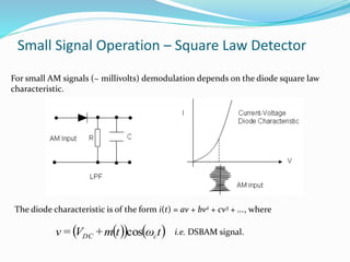
PRESENTED BY
MS.SHANKHA MITRA SUNANI
CONTENT
 Introduction
 Standard equation and its spectrum
 Depth of modulation
 Power consideration in DSBC AM and its
efficiency
 Reconstruction of DSBC AM
INTRODUCTION TO DSBC AM
From the diagram
where VDC is the DC voltage that can be varied.. Expanding the equation we get:
      tωtm+V=tv cDCs cos
       tωtm+tωV=tv ccDCs coscos
Now let m(t) = Vm cos mt, i.e. a 'test' signal,        tωtωV+tωV=tv cmmcDCs coscoscos
    BA+B+A=BA coscos
2
1
coscos we have
         tωω
V
+tω+ω
V
+tωV=tv mc
m
mc
m
cDCs cos
2
cos
2
cos
Components: Carrier USB LSB
Amplitude: VDC Vm/2 Vm/2
Frequency: c c + m c – m
fc fc + fm fc - fm
Modulation Depth Consider again the equation       tωtωV+V=tv cmmDCs coscos
which may be written as
     tωtω
V
V
+V=tv cm
DC
m
DCs coscos1 





The ratio is
DC
m
V
V defined as the modulation depth, m, i.e.
DC
m
V
V
=m
The above are input signals. The diagram below shows the spectrum and
corresponding waveform of the output signal, given by
         tωω
V
+tω+ω
V
+tωV=tv mc
m
mc
m
cDCs cos
2
cos
2
cos
Spectrum and Waveforms
From this we may write two equivalent equations for the total power PT, in a DSBAM signal
42882
22222
mDCmmDC
T
V
+
V
=
V
+
V
+
V
=P
The carrier power
2
2
DC
c
V
=P
44
22
m
P+
m
P+P=P cccT 





2
1
2
m
+P=P cT
and
882
22222
DCDCDC
T
Vm
+
Vm
+
V
=P
ori.e.
Either of these forms may be useful. Since both USB and LSB contain the same information a
useful ratio which shows the proportion of 'useful' power to total power is
2
2
2
2
24
2
1
4
m+
m
=
m
+P
m
P
=
P
P
c
c
T
USB






Power Considerations in DSBAM
Small Signal Operation – Square Law Detector
For small AM signals (~ millivolts) demodulation depends on the diode square law
characteristic.
The diode characteristic is of the form i(t) = av + bv2 + cv3 + ..., where
    tωtm+V=v cDC cos i.e. DSBAM signal.
Small Signal Operation – Square Law Detector
           ...coscos
2
+tωtm+Vb+tωtm+Va cDCcDC
          ...cos2m(t)cos 222
+tωtm+tmV+Vb+tωtCOSaV cDCDCccDC 
          





 tω+tbm+tmbVbV+tωtam+tCOSaV cDCDCcCDC 2cos
2
1
2
1
2cos
22

          ...2cos
222
2
2
coscos
2
22
+tω
V
b+
tbm
+
tmbV
+
bV
+tωtam+taV c
DCDCDC
ccDC 
 tmbV+
bV
DC
2DC
2
=
=
=
'LPF' removes components.
Signal out = i.e. the output contains m(t)
i.e.
THANK YOU

Ppt am

  • 1.
  • 2.
    CONTENT  Introduction  Standardequation and its spectrum  Depth of modulation  Power consideration in DSBC AM and its efficiency  Reconstruction of DSBC AM
  • 3.
    INTRODUCTION TO DSBCAM From the diagram where VDC is the DC voltage that can be varied.. Expanding the equation we get:       tωtm+V=tv cDCs cos        tωtm+tωV=tv ccDCs coscos Now let m(t) = Vm cos mt, i.e. a 'test' signal,        tωtωV+tωV=tv cmmcDCs coscoscos     BA+B+A=BA coscos 2 1 coscos we have          tωω V +tω+ω V +tωV=tv mc m mc m cDCs cos 2 cos 2 cos
  • 4.
    Components: Carrier USBLSB Amplitude: VDC Vm/2 Vm/2 Frequency: c c + m c – m fc fc + fm fc - fm Modulation Depth Consider again the equation       tωtωV+V=tv cmmDCs coscos which may be written as      tωtω V V +V=tv cm DC m DCs coscos1       The ratio is DC m V V defined as the modulation depth, m, i.e. DC m V V =m
  • 5.
    The above areinput signals. The diagram below shows the spectrum and corresponding waveform of the output signal, given by          tωω V +tω+ω V +tωV=tv mc m mc m cDCs cos 2 cos 2 cos Spectrum and Waveforms
  • 6.
    From this wemay write two equivalent equations for the total power PT, in a DSBAM signal 42882 22222 mDCmmDC T V + V = V + V + V =P The carrier power 2 2 DC c V =P 44 22 m P+ m P+P=P cccT       2 1 2 m +P=P cT and 882 22222 DCDCDC T Vm + Vm + V =P ori.e. Either of these forms may be useful. Since both USB and LSB contain the same information a useful ratio which shows the proportion of 'useful' power to total power is 2 2 2 2 24 2 1 4 m+ m = m +P m P = P P c c T USB       Power Considerations in DSBAM
  • 7.
    Small Signal Operation– Square Law Detector For small AM signals (~ millivolts) demodulation depends on the diode square law characteristic. The diode characteristic is of the form i(t) = av + bv2 + cv3 + ..., where     tωtm+V=v cDC cos i.e. DSBAM signal.
  • 8.
    Small Signal Operation– Square Law Detector            ...coscos 2 +tωtm+Vb+tωtm+Va cDCcDC           ...cos2m(t)cos 222 +tωtm+tmV+Vb+tωtCOSaV cDCDCccDC                   tω+tbm+tmbVbV+tωtam+tCOSaV cDCDCcCDC 2cos 2 1 2 1 2cos 22            ...2cos 222 2 2 coscos 2 22 +tω V b+ tbm + tmbV + bV +tωtam+taV c DCDCDC ccDC   tmbV+ bV DC 2DC 2 = = = 'LPF' removes components. Signal out = i.e. the output contains m(t) i.e.
  • 9.