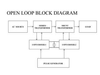
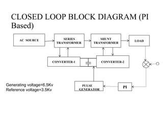
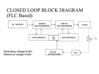
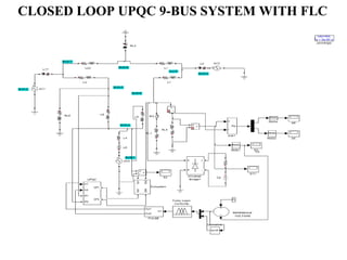
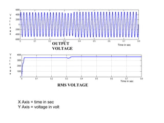
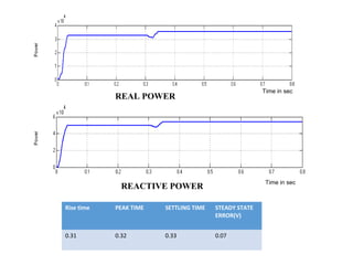
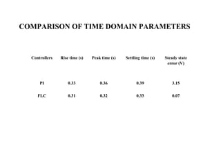
POWER QUALITY IMPROVEMENT WITH UPQC
USING FLC
Guided by: Dr.V.GOMATHI
Student Name:Logumani.V
(2014280011)
CONTENTS
OBJECTIVE
NEED FOR MICRO GRID
WORKDONE
BLOCK DIAGRAM
SIMULATION AND RESULTS
COMPARISON TABLE
REFERENCES
OBJECTIVE
 To maintain the voltage profile variation, real and
reactive power control in the transmission line.
NEED FOR UPQC IN MICROGRID
•The UPQC is combination of STATCOM and DVR
•It can control simultaneously the real power,
reactive power and harmonic current.
•To maintain the voltage with minimal ripple in the
steady state(DC link capacitor).
WORK DONE IN PHASE I
•Basic UPQC system is simulated
•UPQC system in islanded mode is simulated
•UPQC system is interconnected mode is simulated
WORK DONE IN PHASE II
•To investigate the real and reactive power
compensation with UPQC.
•To analyze the closed loop control with PI and
Fuzzy controllers.
•To compare the steady state error and Time domain
parameters like rise time, peak time and settling
time.
OPEN LOOP BLOCK DIAGRAM
AC SOURCE LOAD
SERIES
TRANSFORMER
SHUNT
TRANSFORMER
PULSE GENERATOR
CONVERTER-1 CONVERTER-2
CLOSED LOOP BLOCK DIAGRAM (PI
Based)
AC SOURCE LOAD
SERIES
TRANSFORMER
SHUNT
TRANSFORMER
PULSE
GENERATOR
CONVERTER-1 CONVERTER-2
PI
c
c
Generating voltage=6.5Kv
Reference voltage=3.5Kv
CLOSED LOOP BLOCK DIAGRAM
(FLC Based)
AC SOURCE LOAD
SERIES
TRANSFORMER
SHUNT
TRANSFORMER
PULSE
GENERATOR
CONVERTER-1 CONVERTER-2
FLC
c
c
Generating voltage=6.5Kv
Reference voltage=3.5Kv
CLOSED LOOP UPQC 9-BUS SYSTEM WITH FLC
OUTPUT
VOLTAGE
Time in sec
X Axis = time in sec
Y Axis = voltage in volt
Time in sec
RMS VOLTAGE
REAL POWER
Time in sec
REACTIVE POWER
Time in sec
Time in sec
Rise time PEAK TIME SETTLING TIME STEADY STATE
ERROR(V)
0.31 0.32 0.33 0.07
Controllers Rise time (s) Peak time (s) Settling time (s) Steady state
error (V)
PI 0.33 0.36 0.39 3.15
FLC 0.31 0.32 0.33 0.07
COMPARISON OF TIME DOMAIN PARAMETERS
CONCLUSION
REFERENCES
[1] S. K. Harem, M. Base, and M. F. Conlon, “UPQC for power quality improvement
in DG integrated smart grid network—A review,” Int. J. Emerge. Electra. Power Syst.,
vol. 13, no. 1, p. 3, 2012.
[2] A. Kahrobaeian and Y.-R. Mohamed, “Interactive distributed generation interface
for flexible micro-grid operation in smart distribution systems,” IEEE Trans.
Sustainable Energy, vol. 3, no. 2, pp. 295–305, Apr. 2012.
[3] X. Yu, A. M. Khambadkone, H. Wang, and S. Terence, “Control of parallel-
connected power converters for low-voltage microgrid—Part I: A hybrid control
architecture,” IEEE Trans. Power Electron., vol. 25, no. 12, pp. 2962–2970, Dec. 2010.
[4] S. K. Khadem, M. Basu, and M. F. Conlon, “A new placement and integration
method of UPQC to improve the power quality in DG network,” in Proc. 48th UPEC,
vol. 1. Sep. 2013, pp. 1–6.
[5] T. Jimichi, H. Fujita, and H. Akagi, “Design and experimentation of a dynamic
voltage restorer capable of significantly reducing an energy-storage element,” IEEE
Trans. Ind. Appl., vol. 44, no. 3, pp. 817–825, May/Jun. 2008.
[6] K. S. Khadem, “Power quality improvement of distributed generation
integrated network with unified power quality conditioner,” Ph.D.
dissertation, Dept. Elect. Electron. Eng., Dublin Inst. Technol., Ireland,
Europe, Jan. 2013.
[7] F. Gao and M. R. Iravani, “A control strategy for a distributed
generation unit in grid-connected and autonomous modes of operation,”
IEEE Trans. Power Del., vol. 23, no. 2, pp. 850–859, Apr. 2008.
[8] B. Han, B. Bae, H. Kim, and S. Baek, “Combined operation of unified
power-quality conditioner with distributed generation,” IEEE Trans. Power
Del., vol. 21, no. 1, pp. 330–338, Jan. 2006.
[9] S. K. Khadem, M. Basu, and M. F. Conlon, “Harmonic power
compensation capacity of shunt active power filter and its relationship with
design parameters,” IET Power Electron., vol. 7, no. 2, pp. 418–430, 2013.

POWER QUQLITY IMPROVEMENT WITH UPQC

  • 1.
    POWER QUALITY IMPROVEMENTWITH UPQC USING FLC Guided by: Dr.V.GOMATHI Student Name:Logumani.V (2014280011)
  • 2.
    CONTENTS OBJECTIVE NEED FOR MICROGRID WORKDONE BLOCK DIAGRAM SIMULATION AND RESULTS COMPARISON TABLE REFERENCES
  • 3.
    OBJECTIVE  To maintainthe voltage profile variation, real and reactive power control in the transmission line.
  • 4.
    NEED FOR UPQCIN MICROGRID •The UPQC is combination of STATCOM and DVR •It can control simultaneously the real power, reactive power and harmonic current. •To maintain the voltage with minimal ripple in the steady state(DC link capacitor).
  • 5.
    WORK DONE INPHASE I •Basic UPQC system is simulated •UPQC system in islanded mode is simulated •UPQC system is interconnected mode is simulated
  • 6.
    WORK DONE INPHASE II •To investigate the real and reactive power compensation with UPQC. •To analyze the closed loop control with PI and Fuzzy controllers. •To compare the steady state error and Time domain parameters like rise time, peak time and settling time.
  • 7.
    OPEN LOOP BLOCKDIAGRAM AC SOURCE LOAD SERIES TRANSFORMER SHUNT TRANSFORMER PULSE GENERATOR CONVERTER-1 CONVERTER-2
  • 8.
    CLOSED LOOP BLOCKDIAGRAM (PI Based) AC SOURCE LOAD SERIES TRANSFORMER SHUNT TRANSFORMER PULSE GENERATOR CONVERTER-1 CONVERTER-2 PI c c Generating voltage=6.5Kv Reference voltage=3.5Kv
  • 9.
    CLOSED LOOP BLOCKDIAGRAM (FLC Based) AC SOURCE LOAD SERIES TRANSFORMER SHUNT TRANSFORMER PULSE GENERATOR CONVERTER-1 CONVERTER-2 FLC c c Generating voltage=6.5Kv Reference voltage=3.5Kv
  • 10.
    CLOSED LOOP UPQC9-BUS SYSTEM WITH FLC
  • 11.
    OUTPUT VOLTAGE Time in sec XAxis = time in sec Y Axis = voltage in volt Time in sec RMS VOLTAGE
  • 12.
    REAL POWER Time insec REACTIVE POWER Time in sec Time in sec Rise time PEAK TIME SETTLING TIME STEADY STATE ERROR(V) 0.31 0.32 0.33 0.07
  • 13.
    Controllers Rise time(s) Peak time (s) Settling time (s) Steady state error (V) PI 0.33 0.36 0.39 3.15 FLC 0.31 0.32 0.33 0.07 COMPARISON OF TIME DOMAIN PARAMETERS
  • 14.
  • 15.
    REFERENCES [1] S. K.Harem, M. Base, and M. F. Conlon, “UPQC for power quality improvement in DG integrated smart grid network—A review,” Int. J. Emerge. Electra. Power Syst., vol. 13, no. 1, p. 3, 2012. [2] A. Kahrobaeian and Y.-R. Mohamed, “Interactive distributed generation interface for flexible micro-grid operation in smart distribution systems,” IEEE Trans. Sustainable Energy, vol. 3, no. 2, pp. 295–305, Apr. 2012. [3] X. Yu, A. M. Khambadkone, H. Wang, and S. Terence, “Control of parallel- connected power converters for low-voltage microgrid—Part I: A hybrid control architecture,” IEEE Trans. Power Electron., vol. 25, no. 12, pp. 2962–2970, Dec. 2010. [4] S. K. Khadem, M. Basu, and M. F. Conlon, “A new placement and integration method of UPQC to improve the power quality in DG network,” in Proc. 48th UPEC, vol. 1. Sep. 2013, pp. 1–6. [5] T. Jimichi, H. Fujita, and H. Akagi, “Design and experimentation of a dynamic voltage restorer capable of significantly reducing an energy-storage element,” IEEE Trans. Ind. Appl., vol. 44, no. 3, pp. 817–825, May/Jun. 2008.
  • 16.
    [6] K. S.Khadem, “Power quality improvement of distributed generation integrated network with unified power quality conditioner,” Ph.D. dissertation, Dept. Elect. Electron. Eng., Dublin Inst. Technol., Ireland, Europe, Jan. 2013. [7] F. Gao and M. R. Iravani, “A control strategy for a distributed generation unit in grid-connected and autonomous modes of operation,” IEEE Trans. Power Del., vol. 23, no. 2, pp. 850–859, Apr. 2008. [8] B. Han, B. Bae, H. Kim, and S. Baek, “Combined operation of unified power-quality conditioner with distributed generation,” IEEE Trans. Power Del., vol. 21, no. 1, pp. 330–338, Jan. 2006. [9] S. K. Khadem, M. Basu, and M. F. Conlon, “Harmonic power compensation capacity of shunt active power filter and its relationship with design parameters,” IET Power Electron., vol. 7, no. 2, pp. 418–430, 2013.