Download as PDF, PPTX
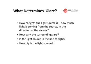
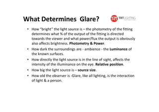
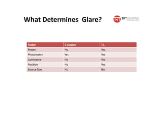
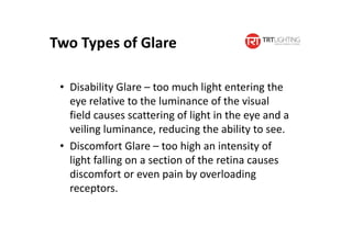
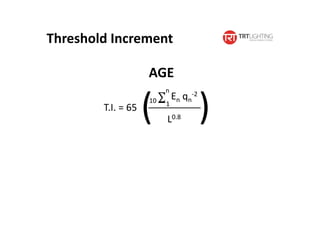
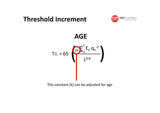
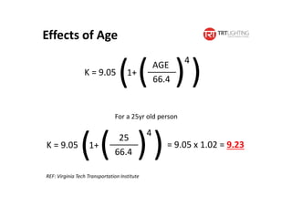
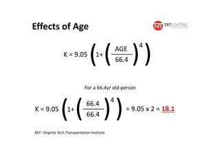
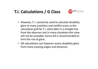
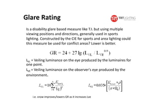
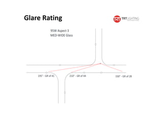
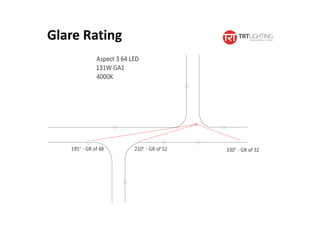
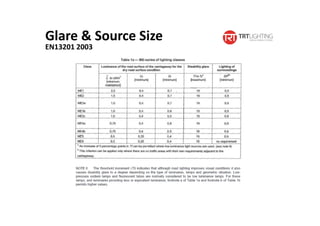
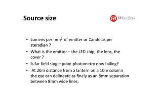
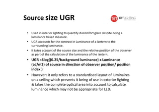
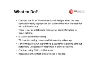

Glare can be caused by disability glare or discomfort glare. Disability glare reduces visibility while discomfort glare causes pain. The Threshold Increment (T.I.) measure quantifies disability glare in road lighting but does not account for discomfort glare or factors like source size. T.I. values should be adjusted upwards for older drivers as glare impacts increase with age. For complex areas like junctions, the Glare Rating (GR) measure may provide a better assessment of disability glare than T.I. or G-classes. Further research is needed on how source size, particularly of LEDs, affects glare.


