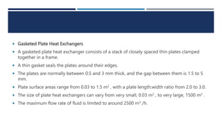
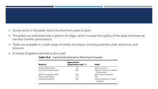
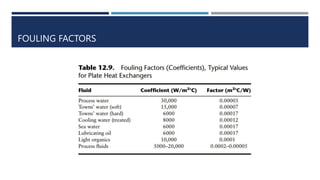
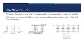
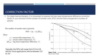
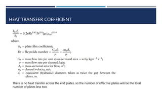
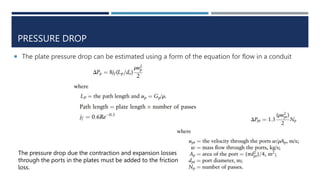
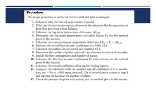
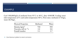
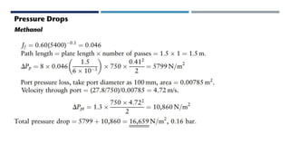
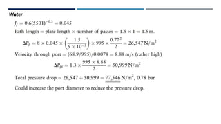
4. Gasketed Plate Heat Exchangers
A gasketed plate heat exchanger consists of a stack of closely spaced thin plates clamped
together in a frame.
A thin gasket seals the plates around their edges.
The plates are normally between 0.5 and 3 mm thick, and the gap between them is 1.5 to 5
mm.
Plate surface areas range from 0.03 to 1.5 m2 , with a plate length:width ratio from 2.0 to 3.0.
The size of plate heat exchangers can vary from very small, 0.03 m2 , to very large, 1500 m2 .
The maximum flow rate of fluid is limited to around 2500 m3 /h.
5. Corner ports in the plates direct the flow from plate to plate.
The plates are embossed with a pattern of ridges, which increase the rigidity of the plate and improve
the heat transfer performance.
Plates are available in a wide range of metals and alloys, including stainless steel, aluminum, and
titanium.
A variety of gasket materials is also used
7. Plate heat exchangers are used extensively in the food and beverage
industries, as they can be readily taken apart for cleaning and inspection.
Their use in the chemical industry will depend on the relative cost for the
application compared with a conventional shell and tube exchanger.
8. FLOW ARRANGEMENTS
The stream flows can be arranged in series or parallel, or a combination of series and parallel.
Each stream can be subdivided into several passes, analogous to the passes used in shell and
tube exchangers
9. CORRECTION FACTOR
For plate heat exchangers, it is convenient to express the log mean temperature difference correction
factor, Ft, as a function of the number of transfer units, NTU, and the flow arrangement (number of
passes)
Typically, the NTU will range from 0.5 to 4.0,
and for most applications will lie between 2.0
to 3.0
10. HEAT TRANSFER COEFFICIENT
There is no heat transfer across the end plates, so the number of effective plates will be the total
number of plates less two
11. PRESSURE DROP
The plate pressure drop can be estimated using a form of the equation for flow in a conduit
The pressure drop due the contraction and expansion losses
through the ports in the plates must be added to the friction
loss.
12. PLATE HEAT EXCHANGER DESIGN
It is not possible to give exact design methods for plate heat exchangers.
They are proprietary designs and will normally be specified in consultation
with the manufacturers.
Information on the performance of the various patterns of plates used is not
generally available.
The approximate method given here can be used to size an exchanger for
comparison with a shell and tube exchanger, and to check performance of an
existing exchanger for new duties.