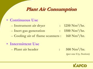
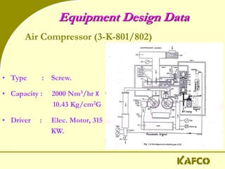
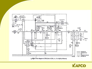
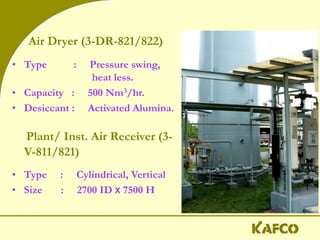
Operation of Plant air &
Instrument air system.
Line-up of Process air,
Problems and
Troubleshooting.
This unit consists of plant air and
instrument air and comprises of basically
two Air Compressors and Dryers. Air is
compressed by air compressors and supplied
to the Air Receiver, from where air is then
supplied to IGG Plant, Plant air header and a
part of this air is passed through a dryer unit
for purification where moisture is absorbed
and the dryer outlet air is supplied to the
Instrument Air Receiver for the use of
different instruments.
In normal operation, compressed
air is extracted from downstream of
the 3rd Separator (1-S-423) of
Process Air Compressor (1-K-402) in
Ammonia Plant and fed to the
Compressed Air Receiver (3-V-811)
via a pressure indicating controller
(3-PIC-801) set at 9.8 Kg/cm2G.
Plant Air Consumption
• Continuous Use
– Instrument air dryer : 1250 Nm3/hr.
– Inert gas generation : 1500 Nm3/hr.
– Cooling air of flame scanners : 160 Nm3/hr.
• Intermittent Use
– Plant air header : 500 Nm3/hr.
(per one Uty. Station)
Equipment Design Data
• Type : Screw.
• Capacity : 2000 Nm3/hr X
10.43 Kg/cm2G
• Driver : Elec. Motor, 315
KW.
Air Compressor (3-K-801/802)
Air Dryer (3-DR-821/822)
• Type : Pressure swing,
heat less.
• Capacity : 500 Nm3/hr.
• Desiccant : Activated Alumina.
Plant/ Inst. Air Receiver (3-
V-811/821)
• Type : Cylindrical, Vertical
• Size : 2700 ID X 7500 H
Start-up of Plant Air System
Start-up of Air Compressors (3-K-
801/802) after prolonged
shutdown shall always be carried
out locally to assure safe and
stable operation of the
compressors.
Start-up Preparation:
• Confirm availability of the following utilities:
• Electric Power
• Cooling Water
• CLOSE the valves 3-PV-801 and 802, 3-PV-803 A, 3-PV-807,
along with the upstream block valves and by pass valves of
the control valves.
• OPEN cooling water line isolation valves to the
compressors.
• OPEN the discharge valves of the compressors.
• CHECK lube oil levels in the compressors are OK.
• Open all the instrument block valves.
Local Start-up of Air Compressors:
• Put the selector of the compressor 3-K-801/802 into LOCAL position.
• Move the toggle switch of UNLOAD/NORMAL to UNLOAD position.
• Take final clearance from Power Generation Section to START the
Compressor 3-K-801/802.
• Press RESET-START button to start (1st) the Compressor. Check that
oil pressure is over 1.2 kg/cm2 G. There is no vibration, abnormal
sound, lube oil or water leakage.
• Move the toggle switch to
NORMAL position after 3/4 min
to load the compressor and
pressurize the Compressed
Air Receiver (3-V-811).
• Look for cooling water return line temperature and regulate
this so that the temperature rise is within 100 C.
• Slowly pressurize the air Receiver to normal operating
pressure of 9.8 kg/cm2G and slowly open the air outlet to
other consumers.
• Confirm that the compressor operation shifts to “unloaded
operation” automatically when discharge pressure reaches
to preset unloading pressure. Also confirm the “loaded
operation”.
• Start 2nd Compressor as the same procedure for 1st and
confirm load/unload function of this Compressor.
A. Change Over from Utility Compressors to Process Air:
 Both the compressors are running with loading/unloading
operation.
 Take clearance from CCR to receive process air from Ammonia.
 Open U/S isolation valve of 3-PIC-801 slowly. This will increase the
Air Receiver pressure.
 So, the compressors discharge pressure will also increase to
unloading set point (i.e. 9.6 & 9.7 Kg/cm2G.). And the result will
both the compressors undergo unloading operation.
 After 20 minutes of unloading operation the compressor will stop
automatically one by one to auto stand-by position.
Automatic Operation of Air Compressors:
B. Change Over from Process Air to Utility Compressors:
 Confirm both the Compressors are auto stand-by position.
 Check CW line isolation valves are open & L/O level OK.
 Check discharge valves of the compressors open.
 Take clearance for compressor start-up and to cut Process Air
from Power Generation & Ammonia Plant.
 Close U/S isolation valve of 3-PIC-801 slowly.
 When isolation valve almost close, Air Receiver pressure
decreases to auto start set point (i.e. PAL-9.5 & PALL-9.4
Kg/cm2G.) and the compressors start automatically one by one.
 Confirm loading/unloading function of the Compressors.
Tea Break !!
P & I Diagram of
Plant air & Instrument air system
Line-up of Instrument Air System:
A. Instrument Air Receiver (3-V-821) Line-up:
o Pressurize 3-V-821 by opening bypass valve of 3-PV-802 and 3-DR-
821/822 upto 7 kg/cm2G (slowly).
o Then open isolation valve of 3-PV-802 and put 3-PIC-802 into service.
o Confirm 3-PIC-802 is operating on
automatic at set-point 8.0 kg/cm2G.
o Close the bypass valve of 3-PV-802.
B. Line-up Air Dryers:
o Open the block valves to Pre-filters and partially open the block
valves of the After-filter.
o Adjust the moisture indicator bleed valve such that only small
amount of air is felt flowing.
o Confirm pressurization of Dryer & Energize the Dryer.
o Dryer would operate on FIXED mode until the desiccant beds
are regenerated to the extent necessary to obtain dry air at the
dryer's rated dew point. The control system will then
automatically shift to the AMLOC mode.
o Confirm that purge air pressure for regeneration is ~80 psig.
o Close the by-pass valves of 3-DR-821/822.
Line-up Plant Air to Header:
• Confirm Instrument Air pressure normal (~7.8 kg/cm2G
or more than 6.8 kg/cm2G).
• Selection position of 3-PV-803A in Unlatch condition and
PV should be in close position.
• Open slowly the isolation valve of 3-PV-803A to full.
• Open slowly 3-PV-803A by hand-wheel to pressurize
header.
• After pressurization air header, close PV by hand-wheel.
• Change actuator position into Latch and this will open PV
full.
Line-up Plant Air to IGG Plant:
• Confirm Instrument Air pressure normal (~7.8 kg/cm2G or more
than 6.0 kg/cm2G).
• Selection position of 3-PV-803B in Unlatch condition and PV
should be in close position.
• Open slowly the U/S isolation valve of 3-PV-807 to full.
• Open slowly 3-PV-807 through 3-PIC-807 manually.
• Open slowly 3-PV-803B by hand-wheel to pressurize header.
• After pressurization air header, Close 3-PV-803B by hand-wheel.
• Change actuator position into Latch and this will open 3-PV-803B
fully.
• Adjust set of 3-PIC-807 at 9.2 kg/cm2G and put it into auto.
Line-up Plant Air to Boiler Scanner:
After clearance from CCR, open scanner
line isolation valve slowly and lock the
valve for confirmation of always opening.
Shutdown of Plant Air System
• Before shutting down of this unit it must be
required to inform the whole plant.
• Close U/S isolation valve of 3-PV-801
• Turn the switch Loading to Unloading and move
“LOCAL/REMOTE” Switches to “LOCAL”.
• Press stop button of 3-K-801/802
• De-energize the local control panel of one of the air
dryers to stop the operation of the dryer.
• Open drain line of LP and HP line.
Problems and Troubleshooting
Total Power Failure
This failure will cause immediate shutdown of the
process air compressor (1-K-402) due to the stop of
the Flue Gas Fan (1-K-101A/B). Accordingly, the
air compressors (3-K-801/802) backed-up by
emergency power will start automatically.
The action to be taken at the time is to confirm that
the air compressors (3-K-801 / 802) are put into
service and the system is steady.
Cooling Water Failure
In order to prevent cooling water failure which
causes shutdown of the plant air and instrument
air system, cooling water for air compressors is
supplied by critical cooling water system which
is equipped with steam turbine riven pump and
standby motor driven pump backed-up by
emergency power to continue operation even in
case of electrical power failure.
Process Air Failure
• After plant air failed, when air receiver pressure
drops to set point of the air compressors, then
air compressors start automatically.
• Check oil pressure, temperature and lube oil
level are normal.
• Check LP/HP out temperature are normal.
• Close isolation valve of 3-PV-801 and put the
controller into manual.
Air Compressors fail with process air
• Immediately Air receiver pressure will fall, at the
same time Instrument air receiver pressure also
drops.
• Instrument air pressure at 6.8 kg/cm2G, plant
air header supply valve 3-PV-803A will close
automatically.
• Instrument air pressure at 6.0 kg/cm2G IGG
plant header supply valve 3-PV-803B will close
automatically.
Instrument Air Dryer Failure
• If dryer fails then instrument air pressure
will fall. It may cause Plant air header
/IGG air supply disconnection.
• To recover the set pressure OPEN dryer
by pass valve.
Thank You
!!

Plant Air & Inst Air.ppt

  • 1.
    Operation of Plantair & Instrument air system. Line-up of Process air, Problems and Troubleshooting.
  • 2.
    This unit consistsof plant air and instrument air and comprises of basically two Air Compressors and Dryers. Air is compressed by air compressors and supplied to the Air Receiver, from where air is then supplied to IGG Plant, Plant air header and a part of this air is passed through a dryer unit for purification where moisture is absorbed and the dryer outlet air is supplied to the Instrument Air Receiver for the use of different instruments.
  • 3.
    In normal operation,compressed air is extracted from downstream of the 3rd Separator (1-S-423) of Process Air Compressor (1-K-402) in Ammonia Plant and fed to the Compressed Air Receiver (3-V-811) via a pressure indicating controller (3-PIC-801) set at 9.8 Kg/cm2G.
  • 4.
    Plant Air Consumption •Continuous Use – Instrument air dryer : 1250 Nm3/hr. – Inert gas generation : 1500 Nm3/hr. – Cooling air of flame scanners : 160 Nm3/hr. • Intermittent Use – Plant air header : 500 Nm3/hr. (per one Uty. Station)
  • 5.
    Equipment Design Data •Type : Screw. • Capacity : 2000 Nm3/hr X 10.43 Kg/cm2G • Driver : Elec. Motor, 315 KW. Air Compressor (3-K-801/802)
  • 7.
    Air Dryer (3-DR-821/822) •Type : Pressure swing, heat less. • Capacity : 500 Nm3/hr. • Desiccant : Activated Alumina. Plant/ Inst. Air Receiver (3- V-811/821) • Type : Cylindrical, Vertical • Size : 2700 ID X 7500 H
  • 8.
    Start-up of PlantAir System Start-up of Air Compressors (3-K- 801/802) after prolonged shutdown shall always be carried out locally to assure safe and stable operation of the compressors.
  • 9.
    Start-up Preparation: • Confirmavailability of the following utilities: • Electric Power • Cooling Water • CLOSE the valves 3-PV-801 and 802, 3-PV-803 A, 3-PV-807, along with the upstream block valves and by pass valves of the control valves. • OPEN cooling water line isolation valves to the compressors. • OPEN the discharge valves of the compressors. • CHECK lube oil levels in the compressors are OK. • Open all the instrument block valves.
  • 10.
    Local Start-up ofAir Compressors: • Put the selector of the compressor 3-K-801/802 into LOCAL position. • Move the toggle switch of UNLOAD/NORMAL to UNLOAD position. • Take final clearance from Power Generation Section to START the Compressor 3-K-801/802. • Press RESET-START button to start (1st) the Compressor. Check that oil pressure is over 1.2 kg/cm2 G. There is no vibration, abnormal sound, lube oil or water leakage. • Move the toggle switch to NORMAL position after 3/4 min to load the compressor and pressurize the Compressed Air Receiver (3-V-811).
  • 11.
    • Look forcooling water return line temperature and regulate this so that the temperature rise is within 100 C. • Slowly pressurize the air Receiver to normal operating pressure of 9.8 kg/cm2G and slowly open the air outlet to other consumers. • Confirm that the compressor operation shifts to “unloaded operation” automatically when discharge pressure reaches to preset unloading pressure. Also confirm the “loaded operation”. • Start 2nd Compressor as the same procedure for 1st and confirm load/unload function of this Compressor.
  • 12.
    A. Change Overfrom Utility Compressors to Process Air:  Both the compressors are running with loading/unloading operation.  Take clearance from CCR to receive process air from Ammonia.  Open U/S isolation valve of 3-PIC-801 slowly. This will increase the Air Receiver pressure.  So, the compressors discharge pressure will also increase to unloading set point (i.e. 9.6 & 9.7 Kg/cm2G.). And the result will both the compressors undergo unloading operation.  After 20 minutes of unloading operation the compressor will stop automatically one by one to auto stand-by position. Automatic Operation of Air Compressors:
  • 13.
    B. Change Overfrom Process Air to Utility Compressors:  Confirm both the Compressors are auto stand-by position.  Check CW line isolation valves are open & L/O level OK.  Check discharge valves of the compressors open.  Take clearance for compressor start-up and to cut Process Air from Power Generation & Ammonia Plant.  Close U/S isolation valve of 3-PIC-801 slowly.  When isolation valve almost close, Air Receiver pressure decreases to auto start set point (i.e. PAL-9.5 & PALL-9.4 Kg/cm2G.) and the compressors start automatically one by one.  Confirm loading/unloading function of the Compressors.
  • 14.
  • 15.
    P & IDiagram of Plant air & Instrument air system
  • 16.
    Line-up of InstrumentAir System: A. Instrument Air Receiver (3-V-821) Line-up: o Pressurize 3-V-821 by opening bypass valve of 3-PV-802 and 3-DR- 821/822 upto 7 kg/cm2G (slowly). o Then open isolation valve of 3-PV-802 and put 3-PIC-802 into service. o Confirm 3-PIC-802 is operating on automatic at set-point 8.0 kg/cm2G. o Close the bypass valve of 3-PV-802.
  • 17.
    B. Line-up AirDryers: o Open the block valves to Pre-filters and partially open the block valves of the After-filter. o Adjust the moisture indicator bleed valve such that only small amount of air is felt flowing. o Confirm pressurization of Dryer & Energize the Dryer. o Dryer would operate on FIXED mode until the desiccant beds are regenerated to the extent necessary to obtain dry air at the dryer's rated dew point. The control system will then automatically shift to the AMLOC mode. o Confirm that purge air pressure for regeneration is ~80 psig. o Close the by-pass valves of 3-DR-821/822.
  • 18.
    Line-up Plant Airto Header: • Confirm Instrument Air pressure normal (~7.8 kg/cm2G or more than 6.8 kg/cm2G). • Selection position of 3-PV-803A in Unlatch condition and PV should be in close position. • Open slowly the isolation valve of 3-PV-803A to full. • Open slowly 3-PV-803A by hand-wheel to pressurize header. • After pressurization air header, close PV by hand-wheel. • Change actuator position into Latch and this will open PV full.
  • 19.
    Line-up Plant Airto IGG Plant: • Confirm Instrument Air pressure normal (~7.8 kg/cm2G or more than 6.0 kg/cm2G). • Selection position of 3-PV-803B in Unlatch condition and PV should be in close position. • Open slowly the U/S isolation valve of 3-PV-807 to full. • Open slowly 3-PV-807 through 3-PIC-807 manually. • Open slowly 3-PV-803B by hand-wheel to pressurize header. • After pressurization air header, Close 3-PV-803B by hand-wheel. • Change actuator position into Latch and this will open 3-PV-803B fully. • Adjust set of 3-PIC-807 at 9.2 kg/cm2G and put it into auto.
  • 20.
    Line-up Plant Airto Boiler Scanner: After clearance from CCR, open scanner line isolation valve slowly and lock the valve for confirmation of always opening.
  • 21.
    Shutdown of PlantAir System • Before shutting down of this unit it must be required to inform the whole plant. • Close U/S isolation valve of 3-PV-801 • Turn the switch Loading to Unloading and move “LOCAL/REMOTE” Switches to “LOCAL”. • Press stop button of 3-K-801/802 • De-energize the local control panel of one of the air dryers to stop the operation of the dryer. • Open drain line of LP and HP line.
  • 22.
    Problems and Troubleshooting TotalPower Failure This failure will cause immediate shutdown of the process air compressor (1-K-402) due to the stop of the Flue Gas Fan (1-K-101A/B). Accordingly, the air compressors (3-K-801/802) backed-up by emergency power will start automatically. The action to be taken at the time is to confirm that the air compressors (3-K-801 / 802) are put into service and the system is steady.
  • 23.
    Cooling Water Failure Inorder to prevent cooling water failure which causes shutdown of the plant air and instrument air system, cooling water for air compressors is supplied by critical cooling water system which is equipped with steam turbine riven pump and standby motor driven pump backed-up by emergency power to continue operation even in case of electrical power failure.
  • 24.
    Process Air Failure •After plant air failed, when air receiver pressure drops to set point of the air compressors, then air compressors start automatically. • Check oil pressure, temperature and lube oil level are normal. • Check LP/HP out temperature are normal. • Close isolation valve of 3-PV-801 and put the controller into manual.
  • 25.
    Air Compressors failwith process air • Immediately Air receiver pressure will fall, at the same time Instrument air receiver pressure also drops. • Instrument air pressure at 6.8 kg/cm2G, plant air header supply valve 3-PV-803A will close automatically. • Instrument air pressure at 6.0 kg/cm2G IGG plant header supply valve 3-PV-803B will close automatically.
  • 26.
    Instrument Air DryerFailure • If dryer fails then instrument air pressure will fall. It may cause Plant air header /IGG air supply disconnection. • To recover the set pressure OPEN dryer by pass valve.
  • 27.