Electrodynamics
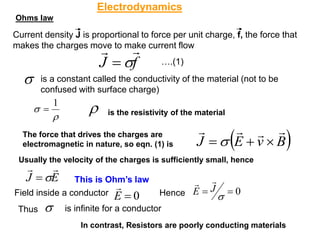
Ohms law
Current densityJ is proportional to force per unit charge, f, the force that
makes the charges move to make current flow
f
J
=
is a constant called the conductivity of the material (not to be
confused with surface charge)
1
= is the resistivity of the material
The force that drives the charges are
electromagnetic in nature, so eqn. (1) is ( )
B
v
E
J
+
=
Usually the velocity of the charges is sufficiently small, hence
E
J
= This is Ohm’s law
is infinite for a conductor
0
=
=
J
E
In contrast, Resistors are poorly conducting materials
….(1)
0
E =
Field inside a conductor Hence
Thus
2.
E
A
z
L
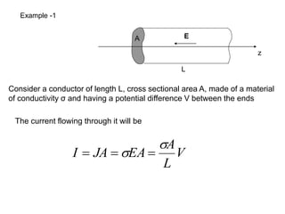
V
L
A
EA
JA
I
=
=
=
Example -1
Considera conductor of length L, cross sectional area A, made of a material
of conductivity σ and having a potential difference V between the ends
The current flowing through it will be
3.
a
b
E
L
s
e
s
E ˆ
2 0
=
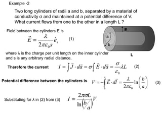
Thereforethe current L
a
d
E
a
d
J
I
=
=
=
0
Potential difference between the cylinders is
0
ln
2
a
b
b
V E dl
a
= − =
( )V
a
b
L
I
ln
2
=
Example -2
Two long cylinders of radii a and b, separated by a material of
conductivity σ and maintained at a potential difference of V.
What current flows from one to the other in a length L ?
Field between the cylinders E is
where λ is the charge per unit length on the inner cylinder
and s is any arbitrary radial distance.
Substituting for λ in (2) from (3)
(1)
(2)
(3)
4.
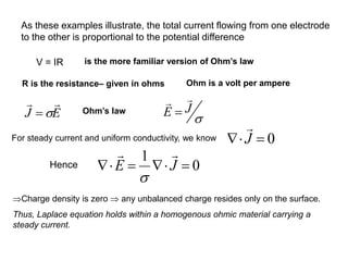
V = IRis the more familiar version of Ohm’s law
R is the resistance– given in ohms Ohm is a volt per ampere
For steady current and uniform conductivity, we know
0
1
=
=
J
E
Charge density is zero any unbalanced charge resides only on the surface.
Thus, Laplace equation holds within a homogenous ohmic material carrying a
steady current.
As these examples illustrate, the total current flowing from one electrode
to the other is proportional to the potential difference
E
J
= Ohm’s law J
E
=
0
J
=
Hence
5.
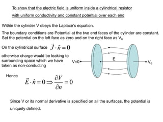
To show thatthe electric field is uniform inside a cylindrical resistor
with uniform conductivity and constant potential over each end
V=0 V0
E
Within the cylinder V obeys the Laplace’s equation.
The boundary conditions are Potential at the two end faces of the cylinder are constant.
Set the potential on the left face as zero and on the right face as V0
On the cylindrical surface
ˆ 0 0
V
E n
n
= =
Since V or its normal derivative is specified on all the surfaces, the potential is
uniquely defined.
ˆ 0
J n
=
otherwise charge would be leaking to
surrounding space which we have
taken as non-conducting
Hence
6.
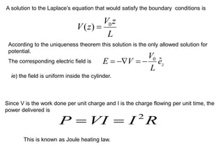
A solution tothe Laplace’s equation that would satisfy the boundary conditions is
L
z
V
z
V 0
)
( =
According to the uniqueness theorem this solution is the only allowed solution for
potential.
The corresponding electric field is
z
e
L
V
V
E ˆ
0
−
=
−
=
ie) the field is uniform inside the cylinder.
Since V is the work done per unit charge and I is the charge flowing per unit time, the
power delivered is
R
I
VI
P 2
=
=
This is known as Joule heating law.
7.
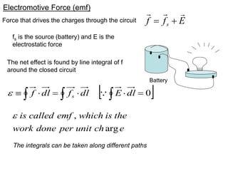
Electromotive Force (emf)
Battery
E
f
fs
+
=
Force that drives the charges through the circuit
0
=
=
dl
E
dl
f
dl
f s
fs is the source (battery) and E is the
electrostatic force
The net effect is found by line integral of f
around the closed circuit
,
arg
is called emf which is the
work done per unit ch e
The integrals can be taken along different paths
8.
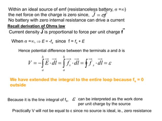
Within an idealsource of emf (resistanceless battery, =)
the net force on the charge is zero since,
No battery with zero internal resistance can drive a current
=
=
=
−
=
dl
f
dl
f
dl
E
V s
b
a
b
a
s
Recall derivation of Ohms law
Current density J is proportional to force per unit charge f
f
J
=
When =, E = -fs since f = fs + E
Hence potential difference between the terminals a and b is
Because it is the line integral of fs, can be interpreted as the work done
per unit charge by the source
We have extended the integral to the entire loop because fs = 0
outside
Practically V will not be equal to ε since no source is ideal, ie., zero resistance
9.
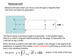
Motional emf
h v
a
bc
d
x R
Motional emf arise when you move a wire through a magnetic field
-this forms the basis for generators
The figure shows a primitive model of a generator. In the shaded region,
there is a uniform magnetic field B pointing into the page. R represents the
Load (let us say, a bulb)
When the loop is pulled to the right with a speed v, the charges in the segment ab
experience a magnetic force whose vertical component qvB drives a current in the
loop in the clockwise direction.
vBh
dl
f mag =
=
The emf is: where h is the width of the loop
10.
fpull
w
v
u
vB
uB
uB
fpull =
=
=
=
vBh
h
uB
dl
fpull sin
cos
)
(
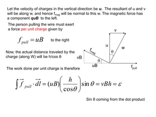
Let the velocity of charges in the vertical direction be u. The resultant of u and v
will be along w, and hence fmag will be normal to this w. The magnetic force has
a component quB to the left.
The person pulling the wire must exert
a force per unit charge given by
to the right
Now, the actual distance traveled by the
charge (along W) will be h/cos θ
The work done per unit charge is therefore
Sin θ coming from the dot product
11.
dt
d
Bhv
dt
dx
Bh
dt
d
Bhx
da
B
−
=
−
=
=
=
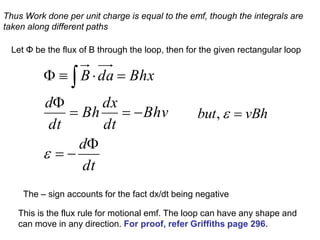
Thus Workdone per unit charge is equal to the emf, though the integrals are
taken along different paths
Let Φ be the flux of B through the loop, then for the given rectangular loop
The – sign accounts for the fact dx/dt being negative
This is the flux rule for motional emf. The loop can have any shape and
can move in any direction. For proof, refer Griffiths page 296.
,
but vBh
=
12.
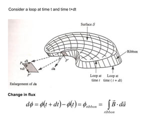
Change in flux
() ( )
=
=
−
+
=
ribbon
ribbon a
d
B
t
dt
t
d
Consider a loop at time t and time t+dt
13.
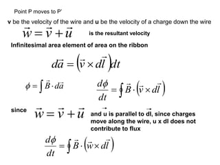
v be thevelocity of the wire and u be the velocity of a charge down the wire
u
v
w
+
= is the resultant velocity
Infinitesimal area element of area on the ribbon
( )dt
l
d
v
a
d
=
( )
= l
d
v
B
dt
d
since
u
v
w
+
= and u is parallel to dl, since charges
move along the wire, u x dl does not
contribute to flux
( )
= l
d
w
B
dt
d
Point P moves to P’
B da
=
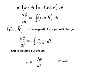
14.
( ) () l
d
B
w
l
d
w
B
−
=
( ) l
d
B
w
dt
d
−
=
( )
B
w
Is the magnetic force per unit charge
l
d
f
dt
d
mag
−
=
RHS is nothing but the emf
dt
d
−
= (Proved)
15.
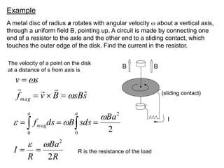
Example
A metal discof radius a rotates with angular velocity about a vertical axis,
through a uniform field B, pointing up. A circuit is made by connecting one
end of a resistor to the axle and the other end to a sliding contact, which
touches the outer edge of the disk. Find the current in the resistor.
B B
(sliding contact)
s
sB
B
v
f
s
v
mag
ˆ
=
=
=
R
Ba
R
I
Ba
sds
B
ds
f
a a
mag
2
2
2
0 0
2
=
=
=
=
=
I
The velocity of a point on the disk
at a distance of s from axis is
R is the resistance of the load
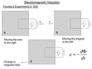
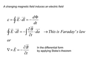
A changing magneticfield induces an electric field
'
d
E dl
dt
B
E dl da This is Faraday s law
t
or
B
E
t
= = −
= − →
= −
In the differential form
by applying Stoke’s theorem
18.
Example
A long cylindricalmagnet of length L and radius a carries a uniform
magnetization M parallel to its axis. It passes at constant velocity v through a
circular wire ring of slightly larger diameter. Show the variation of emf induced
in the ring as a function of time.
L
The magnetic field is the same as that of a long solenoid with surface current,
M
B
is
inside
field
The
e
M
Kb
0
ˆ
=
=
19.
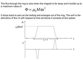
The flux throughthe ring is zero when the magnet is far away and it builds up to
a maximum value of
2
0 a
M
=
It drops back to zero as the trailing end emerges out of the ring. The emf is the
derivative of flux with respect to time ad hence it consists of two spikes.
t
t
0Ma2
L / v
20.
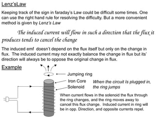
Lenz’sLaw
Keeping track ofthe sign in faraday’s Law could be difficult some times. One
can use the right hand rule for resolving the difficulty. But a more convenient
method is given by Lenz’s Law
The induced current will flow in such a direction that the flux it
produces tends to cancel the change
The induced emf doesn’t depend on the flux itself but only on the change in
flux. The induced current may not exactly balance the change in flux but its’
direction will always be to oppose the original change in flux.
Example
Jumping ring
Solenoid
Iron Core When the circuit Is plugged in,
the ring jumps
When current flows in the solenoid the flux through
the ring changes, and the ring moves away to
cancel this flux change. Induced current in ring will
be in opp. Direction, and opposite currents repel.
21.
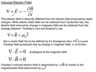
Induced Electric Field
t
B
E
−
=
Thiselectric field is distinctly different from the electric field produced by static
charges. While electro static field can be obtained from Coulomb’s law, the
electric field induced by change in magnetic field can be obtained from the
analogy between Faraday’s Law and Ampere’s Law.
J
B
0
=
But a vector field has to be defined by it’s divergence also. If E is a pure
Faraday field (produced only by change in magnetic field, ie. ρ=0) then
0
=
E
Analogous to the magnetic field
0
=
B
Faraday’s induced electric field is determined by –(B/t) similar to the
magnetostatic field determined by 0J
22.
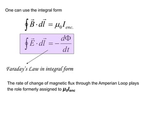
One can usethe integral form
−
=
=
dt
d
l
d
E
I
l
d
B enc
.
0
Faraday’s Law in integral form
The rate of change of magnetic flux through the Amperian Loop plays
the role formerly assigned to μ0Ienc
23.
We have seen
B
E
t
= −
This is Faraday’s law in differential form
(also one of Maxwell’s equations)
This can be written as follows
( )
A A
E
t t
= − =−
0
A
E
t
+ =
Since the curl is irrotational, this is the gradient of the scalar potential
A
E grad
t
A
E grad
t
+ = −
= − −
For time varying fields, there is a contribution from vector potential A.
For stationary fields, E = - grad Φ
24.
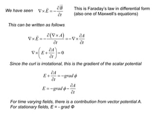
Example
A uniform magneticfield B(t), pointing straight up, fills the shaded circular
region as shown in Fig. If B is changing with time, what is the induced electric
field?
Amperian loop of radius
E points in the circumferential direction, just
like the magnetic field inside a long straight
wire carrying a uniform current density.
Draw an Amperian loop of radius and
apply Faraday’s law in integral form
( )
e
dt
dB
E
dt
dB
t
B
dt
d
dt
d
E
l
d
E
ˆ
2
)
(
)
2
( 2
2
−
=
−
=
−
=
−
=
=
If B is increasing, E runs clockwise, as
viewed from above
25.
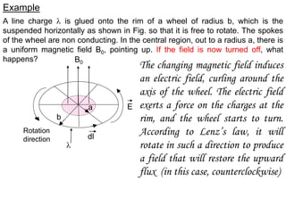
Example
A line charge is glued onto the rim of a wheel of radius b, which is the
suspended horizontally as shown in Fig. so that it is free to rotate. The spokes
of the wheel are non conducting. In the central region, out to a radius a, there is
a uniform magnetic field B0, pointing up. If the field is now turned off, what
happens?
b
a
dl
Rotation
direction
E
B0
The changing magnetic field induces
an electric field, curling around the
axis of the wheel. The electric field
exerts a force on the charges at the
rim, and the wheel starts to turn.
According to Lenz’s law, it will
rotate in such a direction to produce
a field that will restore the upward
flux (in this case, counterclockwise)
26.
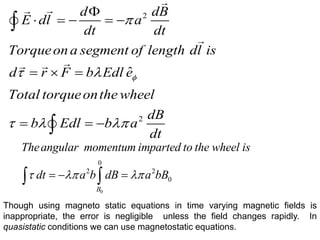
2
2
ˆ
d dB
E dla
dt dt
Torqueona segment of length dl is
d r F b Edl e
Total torqueonthe wheel
dB
b Edl b a
dt
= − = −
= =
= = −
0
0
2 2
0
B
Theangular momentum imparted to the wheel is
dt a b dB a bB
= − =
Though using magneto static equations in time varying magnetic fields is
inappropriate, the error is negligible unless the field changes rapidly. In
quasistatic conditions we can use magnetostatic equations.
27.
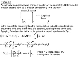
Example
An infinitely longstraight wire carries a slowly varying current I(t). Determine the
induced electric field, as a function of distance from the wire.
0
I
l
Amperian
Loop
In the quasistatic approximation the magnetic field is (0I/2) and it circles
around the wire. Like the B–field of a solenoid, E runs parallel to the axis.
Applying Faraday’s law to the rectangular Amperian loop shown in Fig.,
0
0
0 0
0
0
( ) ( )
1
(ln ln )
2 2
ˆ
( ) ln
2
z
d
E dl E l E l B da
dt
l l
dI dI
d
dt dt
dI
E K e
dt
= − = −
= − = − −
= +
Where K is independent of
but may be a function of t
28.
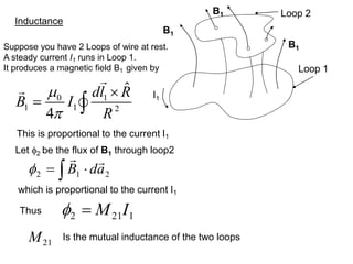
Inductance
B1
B1
B1
Loop 1
Loop 2
I1
Let2 be the flux of B1 through loop2
0 1
1 1 2
ˆ
4
dl R
B I
R
=
2
1
2 a
d
B
=
1
21
2 I
M
=
Thus
21
M Is the mutual inductance of the two loops
Suppose you have 2 Loops of wire at rest.
A steady current I1 runs in Loop 1.
It produces a magnetic field B1 given by
This is proportional to the current I1
which is proportional to the current I1
29.
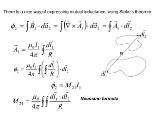
There is anice way of expressing mutual inductance, using Stoke’s theorem
( ) 2
1
2
1
2
1
2 l
d
A
a
d
A
a
d
B
=
=
=
R
1
l
d
2
l
d
=
R
l
d
I
A 1
1
0
1
4
2
1
1
0
2
4
l
d
R
l
d
I
=
1
21
2 I
M
=
=
R
l
d
l
d
M 2
1
0
21
4
Neumann formula
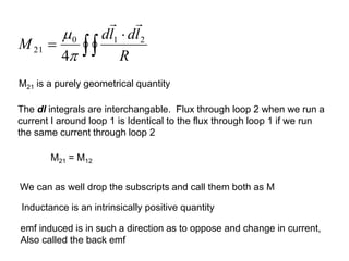
30.
M21 is apurely geometrical quantity
M21 = M12
The dl integrals are interchangable. Flux through loop 2 when we run a
current I around loop 1 is Identical to the flux through loop 1 if we run
the same current through loop 2
=
R
l
d
l
d
M 2
1
0
21
4
We can as well drop the subscripts and call them both as M
Inductance is an intrinsically positive quantity
emf induced is in such a direction as to oppose and change in current,
Also called the back emf
31.
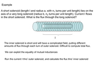
Example
A short solenoid(length l and radius a, with n1 turns per unit length) lies on the
axis of a very long solenoid (radius b, n2 turns per unit length). Current I flows
in the short solenoid. What is the flux through the long solenoid?
l
The inner solenoid is short and will have a complicated field, putting different
amounts of flux through each turn of outer solenoid. Difficult to compute total flux.
We can exploit the equality of mutual inductances
Run the current I thro’ outer solenoid, and calculate the flux thro’ inner solenoid
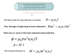
32.
l
I
n
B 2
0
=
Flux througha single loop of inner solenoid is
2
2
0
2
a
I
n
a
B
=
There are n1l turns in the inner solenoid, hence total flux
2
0 1 2
a n n lI
=
l
n
n
a
M 2
1
2
0
=
The field inside the long solenoid is constant.
The mutual inductance is
M I
=
33.
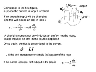
Going back tothe first figure,
suppose the current in loop 1 is varied
Flux through loop 2 will be changing
and this will induce an emf in loop 2
dt
dI
M
dt
d 1
2
2 −
=
−
=
A changing current not only induces an emf on nearby loops,
it also induces an emf in the source loop itself
LI
=
L is the self inductance or simply inductance of the loop
If the current changes, emf induced in the loop is
dt
dI
L
−
=
B1
B1
B1
Loop 1
Loop 2
I1
Once again, the flux is proportional to the current
34.
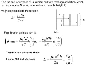
Find the selfinductance of a toroidal coil with rectangular section, which
carries a total of N turns, inner radius a, outer b, height h)
h
a
s
b
Axis
Magnetic field inside the toroid is
0
2
NI
B
s
=
Flux through a single turn is
=
=
a
b
NIh
ds
s
h
NI
a
d
B
b
a
ln
2
1
2
0
0
Total flux is N times the above
Hence, Self inductance is
=
a
b
h
N
L ln
2
2
0
35.
Energy in MagneticFields
dt
dI
dt
dW
LI
I =
−
=
2
2
1
LI
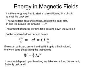
W =
The work done on a unit charge, against the back emf,
in one trip around the circuit is
−
The amount of charge per unit time passing down the wire is I
So the total work done per unit time is
If we start with zero current and build it up to a final value I,
the work done (integrating the last eqn) is
It does not depend upon how long we take to crank up the current,
But only on L and I
It is the energy required to start a current flowing in a circuit
against the back emf
36.
. ( )..
S S p
B da A da Adl
= = =
= l
d
A
LI
.
= l
d
A
I
W
.
2
1
= dl
I
A
W )
.
(
2
1
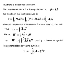
But there is a nicer way to write W
We have seen that the flux through the loop is
where p is the perimeter of the loop and S is any surface bounded by P
LI
=
We also know that the flux is given by
Thus
Hence
or passing on the vector sign to I
The generalization to volume current is
d
J
A
W
= )
.
(
2
1
37.
)
.(
.
)
.( B
A
B
B
B
A
−
=
−
=
d
B
A
d
B
W )
.(
2
2
1
0
J
B
0
=
=
d
B
A
W )
.(
0
2
1
d
J
A
W
= )
.
(
2
1
)
.(
)
.(
)
.( B
A
A
B
B
A
−
=
−
=
S
da
B
A
d
B ).
(
2
2
1
0
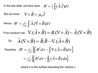
In the last slide, we have seen
But we know
Hence
From product rule
Therefore
So
where s is the surface bounding the volume v
38.
=
space
all
2
2
1
0
d
B
W
=
=
d
E
d
V
Welec
2
2
2
1 0
)
(
=
=
d
B
d
J
A
Wmag
2
2
1
2
1
0
)
.
(
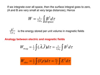
If we integrate over all space, then the surface integral goes to zero,
(A and B are very small at very large distances), Hence
is the energy stored per unit volume in magnetic fields
2
0
2
B
Analogy between electric and magnetic fields
39.
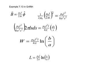
Example 7.13 inGriffith
ˆ
2
0
s
I
B =
( ) 2
2
2
0
0
0 8
2
2
2
1
s
I
s
I
=
( ) ( )
s
ds
l
I
s
I
lsds
4
8
2
0
2
2
2
0
2 =
2
0
4 ln
I l b
W
a
=
( )
a
b
l
L ln
2
0
=