The document is an overview of the 2023 National Electrical Code (NEC), focusing on its purpose, history, and structure, including the legal framework that governs electrical installations. It highlights the importance of the NEC in preventing electrical hazards and its application across various building types, while emphasizing the need to understand conversions between measurement units. The organization of the NEC is outlined, along with the significance of chapters, articles, and annexes for compliance and safety in electrical systems.
![A SunCam Online Continuing Education Course
2023
National Electrical Code
(NEC®
)
OVERVIEW EMPHASIS
Chapters 1-4
General / Wiring & Protection / Wiring Methods & Material / General Use Equipment [Motors]
GENERAL OVERVIEW MATERIAL
Future Courses
Special Equipment [Solar]
Special Conditions [Standby Power]
by
John A Camara, BS, MS, PE, TF
414.pdf](https://image.slidesharecdn.com/414-240704194820-a10247cf/75/NEC-2023-NATIONAL-ELECTRICAL-DODE-2023-NEC-1-2048.jpg)
![2023 National Electric Code (NEC®), OVERVIEW
A SunCam Online Continuing Education Course
www.SunCam.com Copyright©
2023 John A Camara Page 2 of 42
HISTORY and CODE OVERVIEW1
Edison invented the first practical incandescent light bulb in 1879. In the very same year, the
National Association of Fire Engineers met for the purpose of establishing requirements for
electrical installations. As with many standards, in a few years there were six different standards
in place. Therefore, in 1896 the various concerned groups convened a national meeting and one
year later the National Electrical Code (NEC) (hereafter referred to as the “Code”) was born.
The Code is official endorsed by ANSI (American National Standards Institute). The National Fire
Protection Association (NFPA) committee responsible for the code is known as ANSI Standards
Committee C1. The Code is utilized nationwide with local jurisdictions adoption en masse though
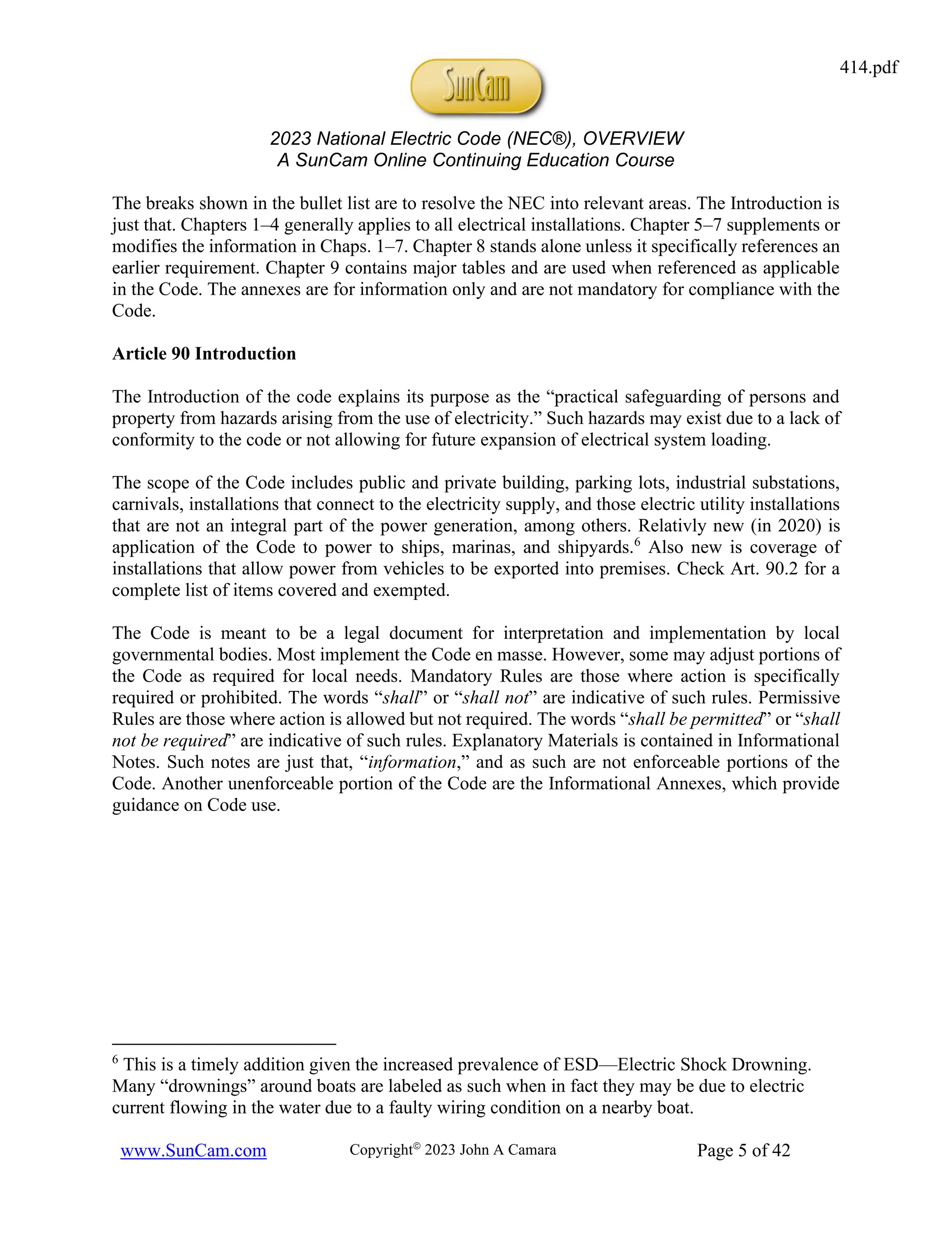
with the occasional supplemental additions or deletions. The Code applies to electrical installations
within or on public and private buildings up to and including connection to the providing power
supply, see Fig. 1. Its overall purpose: prevent fires!
Figure 1: NEC Coverage
[Source: Power Reference Manual for the PE Exam]
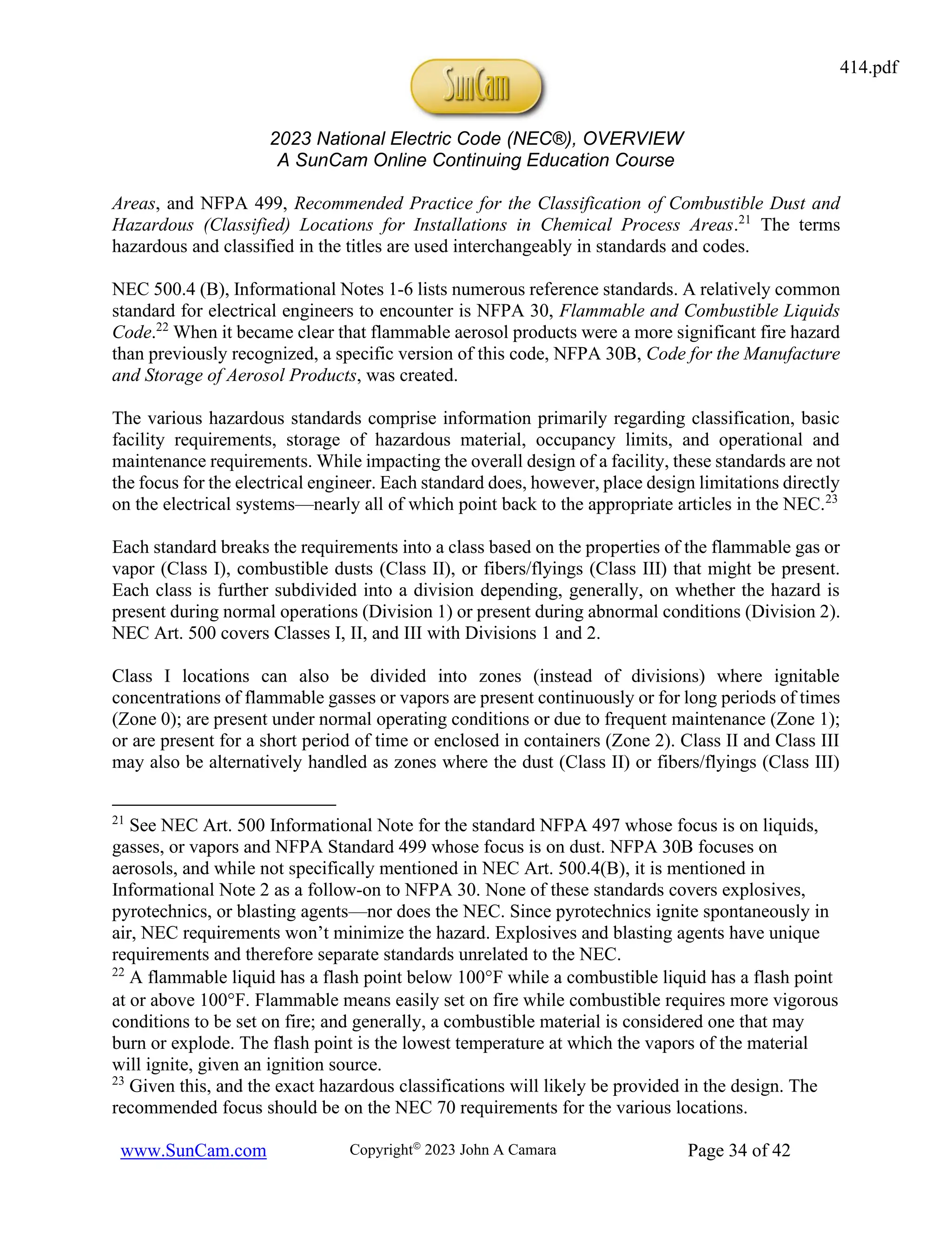
The building code at the international level is International Electrotechnical Commission (IEC)
Standard 60364-1, Electrical Installations of Buildings. The principles of protection and safety in
the IEC code are addressed in the NEC, making it widely applicable.
This course will focus on requirements for such buildings (residential and commercial) and their
internals for items with voltages less than 1000 V. Units will be both SI and USCS (United States
1
Paraphrased from the author’s book published by Professional Publications Incorporated of
Belmont, CA—now a Kaplan Company: John Camara, Power Reference Manual for the PE
Exam, 3rd
ed., (2018), (Kaplan, Inc., 2018), Chap. 56. In the 4th
ed., the NEC is in. Chap. 44.
414.pdf](https://image.slidesharecdn.com/414-240704194820-a10247cf/75/NEC-2023-NATIONAL-ELECTRICAL-DODE-2023-NEC-2-2048.jpg)

![2023 National Electric Code (NEC®), OVERVIEW
A SunCam Online Continuing Education Course
www.SunCam.com Copyright©
2023 John A Camara Page 7 of 42
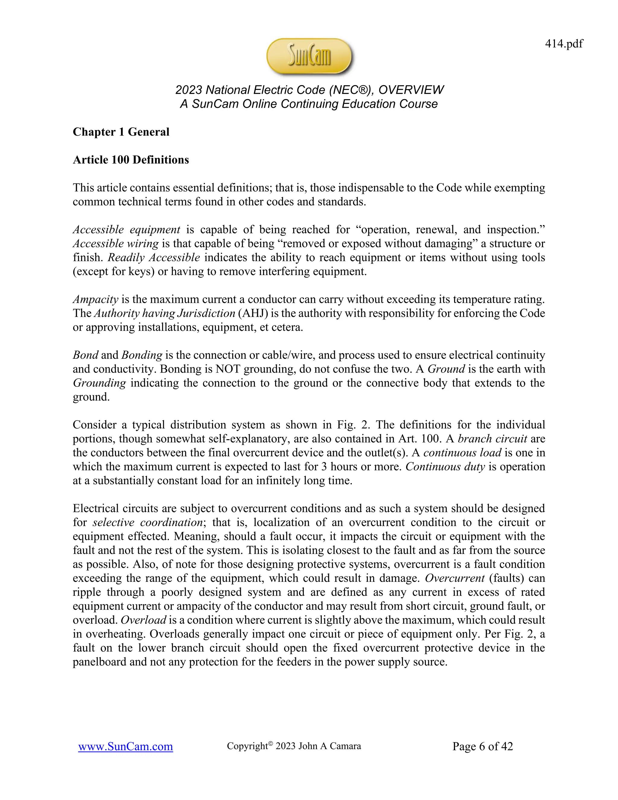
Figure 2: Typical Distribution System
[Source: Power Reference Manual for the PE Exam]
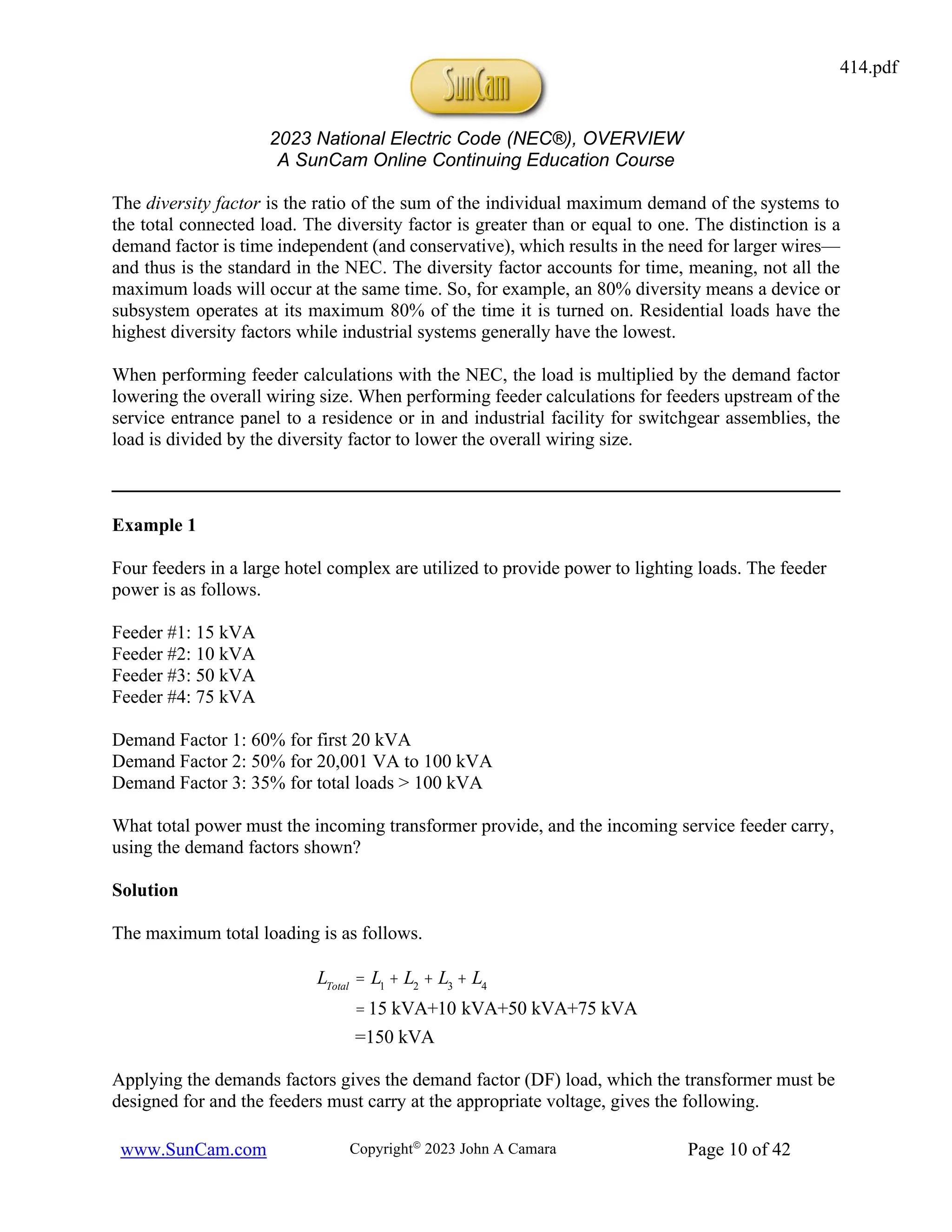
Figure 3 should be referred to for the bonding and grounding explanation that follows. The generic
terms used by electricians and engineers for the grounding wiring doesn’t match-up with the
technical names provided by the NEC, so understanding the differences is very helpful in the field.
A Bonding Conductor or Jumper is a reliable conductor necessary to ensure electrical conductivity
between metal parts. The Bonding Jumper is shown as yellow in the NEC figures. An Equipment
Bonding Jumper provides connection between two or more portions of the Equipment Grounding
Conductor, the latter of which is the green wiring. That is, when all the metal parts are not
electrically connected, the bonding jumper provides the continuity to the grounding (green)
system. Of note, the equipment grounding conductor (green) is NOT meant to carry current under
normal conditions. It is there for safety in the event of a fault to prevent the metal parts from
achieving a voltage above that of earth ground and thus presenting a hazard to people. The
grounding electrode is a conducting object through which a direct connection to Earth. The
grounding electrode conductor connects the system grounded conductor (intentional grounded
conductor—white wire, the neutral) or the equipment grounding conductor (safety ground—green
wire), or both, or to a point on the grounding electrode system.7
The Main Bonding Jumper is the connection between the grounded circuit (service) conductor
(white—commonly called the “neutral”) and the equipment grounding conductor (green—
commonly called the “ground”) or the supply-side bonding jumper, or both. All are shown in Fig.
3. The terminology shown in quotations represents the name one might hear in the field, from
electricians, or those familiar with wiring and its usage.
The numbering and connection scheme on the panelboard in Fig. 3 are standard. The black “hot”
wire is connected to breaker slots #1 and #2. The red “hot” wire is connected to breaker slots #3
and #4. The potential between the red and black wires is 208 V for most households. The potential
7
The “grounded conductor” is almost always the neutral conductor; that is, the white wire. One
exception is a corner grounded delta, which does not have a neutral point but instead grounds
one end of two different phases.
414.pdf](https://image.slidesharecdn.com/414-240704194820-a10247cf/75/NEC-2023-NATIONAL-ELECTRICAL-DODE-2023-NEC-7-2048.jpg)

![2023 National Electric Code (NEC®), OVERVIEW
A SunCam Online Continuing Education Course
www.SunCam.com Copyright©
2023 John A Camara Page 9 of 42
Figure 3: Bonding and Grounding Terminology
The demand factor is the ratio of the maximum demand of the system (or portion thereof) and the
total connected load. This value is always less than one. This is not to be confused with the
diversity factor, which is not found in the NEC—instead it is found in the IEC 61439 (Low Voltage
Switchgear and Control Gear Assemblies), and is used in electrical switchgear designs outside the
purview of the NEC. Think of this as the requirements for industrial low voltage assemblies.
Grounded Circuit Conductor
System Grounded Conductor
Equipment
Grounding
Conductor
2
1
6
5
10
9
14
13
18
17
22
21
26
25
30
29
34
33
4
3
8
7
12
11
16
15
20
19
24
23
28
27
32
31
35
Service Transformer
[Two Phases Shown]
208Y/120V
System Colors
Black--A
Red--B
Blue--C
Supply Side
Equipment Bonding Jumper
Main Bonding Jumper
"Neutral" Hot
Grounding Electrode Conductor
Grounding Electrode
"Ground Rod" or "Ground"
Equipment Grounding Bus
"Safety Ground" or "Green Wire"
EARTH
NEUTRAL BUS
"Neutral" or "White Wire"
414.pdf](https://image.slidesharecdn.com/414-240704194820-a10247cf/75/NEC-2023-NATIONAL-ELECTRICAL-DODE-2023-NEC-9-2048.jpg)
![2023 National Electric Code (NEC®), OVERVIEW
A SunCam Online Continuing Education Course
www.SunCam.com Copyright©
2023 John A Camara Page 15 of 42
Article 210 Branch Circuits
Part I General Provisions
Article 210 cover branch circuits. Regardless of application, one should always start at Table
210.3, which gives the articles pertaining to specific types of branch circuits.
A branch circuit supplying DC loads shall be marked at its positive polarity marked with a red
outer finish, red stripe, a + sign or the word “POSITIVE” or “POS” at least every 24 inches. The
negative polarity shall be marked with a black outer finish, black stripe, a − sign or the word
“NEGATIVE” or “NEG” at least every 24 inches. (Art. 210.5(C)(2)(a) and (b))
A ground-fault circuit interrupter (GFCI) is a device that deenergizes a device within an
established period of time when the current to ground exceeds some predetermined value, which
is less than that required to operate the overcurrent protective device of the supply circuit (see
ground-fault protection of equipment in Art. 100). Such a device is shown in Fig. 4.
Figure 4: Ground-Fault Circuit Interrupter (GFCI)
[Source: Author’s Power Reference Manual]
GFCIs are to be installed in locations required by 210.8(A)-(F). That is, bathrooms, garages,
outdoors, crawl spaces, basements, kitchens, near sinks, boathouses, bathtubs or shower stalls (if
within 1.8 m (6 ft) of the outside edge of tub or stall, laundry areas, and roof tops. Specific
appliances requiring GFCI protection are covered in Art. 422.5 and includes automotive vacuum
machines, drinking water coolers and fill stations, cord- and plug-connected spray washing
machines, tire inflation machines, vending machines, sump pumps, and dishwashers. Many other
articles list requirements for GFCI. See the Handbook Commentary Table 210.1 for a full list. See
Figure 5 for as picture of a GFCI receptacle.
current
transformer
414.pdf](https://image.slidesharecdn.com/414-240704194820-a10247cf/75/NEC-2023-NATIONAL-ELECTRICAL-DODE-2023-NEC-15-2048.jpg)
![2023 National Electric Code (NEC®), OVERVIEW
A SunCam Online Continuing Education Course
www.SunCam.com Copyright©
2023 John A Camara Page 16 of 42
Figure 5: GFCI 20A Receptacle [Test Black / Reset Red]
The number of branch circuits required is generally set by the loads as calculated in Art. 220.10.
But, specific branch circuits are required regardless per Art. 210.11. These include two 20A small
appliance branch circuits, at least one 20A circuit for a laundry receptacle, one or more 20A circuit
for bathroom receptacles, and at least one 20A for garage receptacles.
Relatively new (in 2020) to the requirements is for AFCI (Arc Fault Circuit Interrupter) protection
for all 120V single-phase 15- and 20-ampere branch circuits (see Art. 210.12). Of note, AFCI is
NOT required for a branch circuit supplying a fire alarm system per Art. 210.12(B)(1) Exception.
Ground-fault circuit-interrupter protection for personnel or equipment and arc-fault circuit-
interrupter protection are not allowed to be reconditioned per Art. 210.15.
Article 210
Part II Branch Circuit Ratings
The “rating” of a branch circuit is based on the maximum permitted ampere rating or setting of the
“overcurrent device” and not on the conductor ampacity per 210.18. Standard ratings are 15, 20,
30, 40, and 50 amperes.
The minimum ampacity and size of conductors for Branch Circuits less than 600 V are found in
Art. 210.19, which should be used as the starting point for such research. Section 210.19(A)(1)
sends the reader to Art. 310.14, which takes one to the appropriate ampacity tables. The
Informational Note provides guidance for voltage drops: branch circuit drop of 3% to the farthest
outlet and 5% total to include the feeders. Though the note is technically only guidance it is widely
followed.
The maximum cord-and-plug-connected loading is given in Table 210.21(B)(2). For example, a
15 A receptacle should be loaded to not more than 12 A. Of importance, this is 80% of the possible
414.pdf](https://image.slidesharecdn.com/414-240704194820-a10247cf/75/NEC-2023-NATIONAL-ELECTRICAL-DODE-2023-NEC-16-2048.jpg)
![2023 National Electric Code (NEC®), OVERVIEW
A SunCam Online Continuing Education Course
www.SunCam.com Copyright©
2023 John A Camara Page 19 of 42
NOTE
The sequences in brackets are the NEC articles listed from the initial reference to the final
requirement.
Also, the NEC refers to VA, which is technically apparent power, S. The apparent power is used
for sizing of components to ensure they can handle the power required, P in units of watts (W),
as well as all the losses. The NEC will use the power P rating of equipment as the apparent
power S. I’ve shown both symbols here to emphasize this usage.
General Lighting [Art. 220.83(A)(1); 220.11(B); 220.14(J)]
SLighting
= PL
= 2000 ft2
´ 3
VA
ft2
= 6000 VA
Small Appliance Circuits [Art. 220.83(A)(2); 210.11(C)(1)—2 or more Circuits per
210.52(B)(1); 210.11(C)(2)—1 Laundry Circuit per 210.52(F)]
SSmall Appliance
= PSA
= 3 units ´1500
VA
unit
= 4500 VA
SLaundry
= PLaundry
= 1 units ´1500
VA
unit
=1500 VA
One Electric Range [Art. 220.83(A)(3)b] using the nameplate rating.
SRange
= PR
= 8.5 kW = 8500 VA
One Electric Water Heater [Art. 220.83(A)(3)d] using the nameplate rating.
SWater Heater
= P
WH
= 2.5 kW = 2500 VA
The total existing load is the sum of the loads above.
STotal
= SL
+ SSA
+ SLaundry
+ SR
+ SWH
= 6000 VA + 4500 VA +1500 VA + 8500 VA + 2500 VA
= 23,000 VA
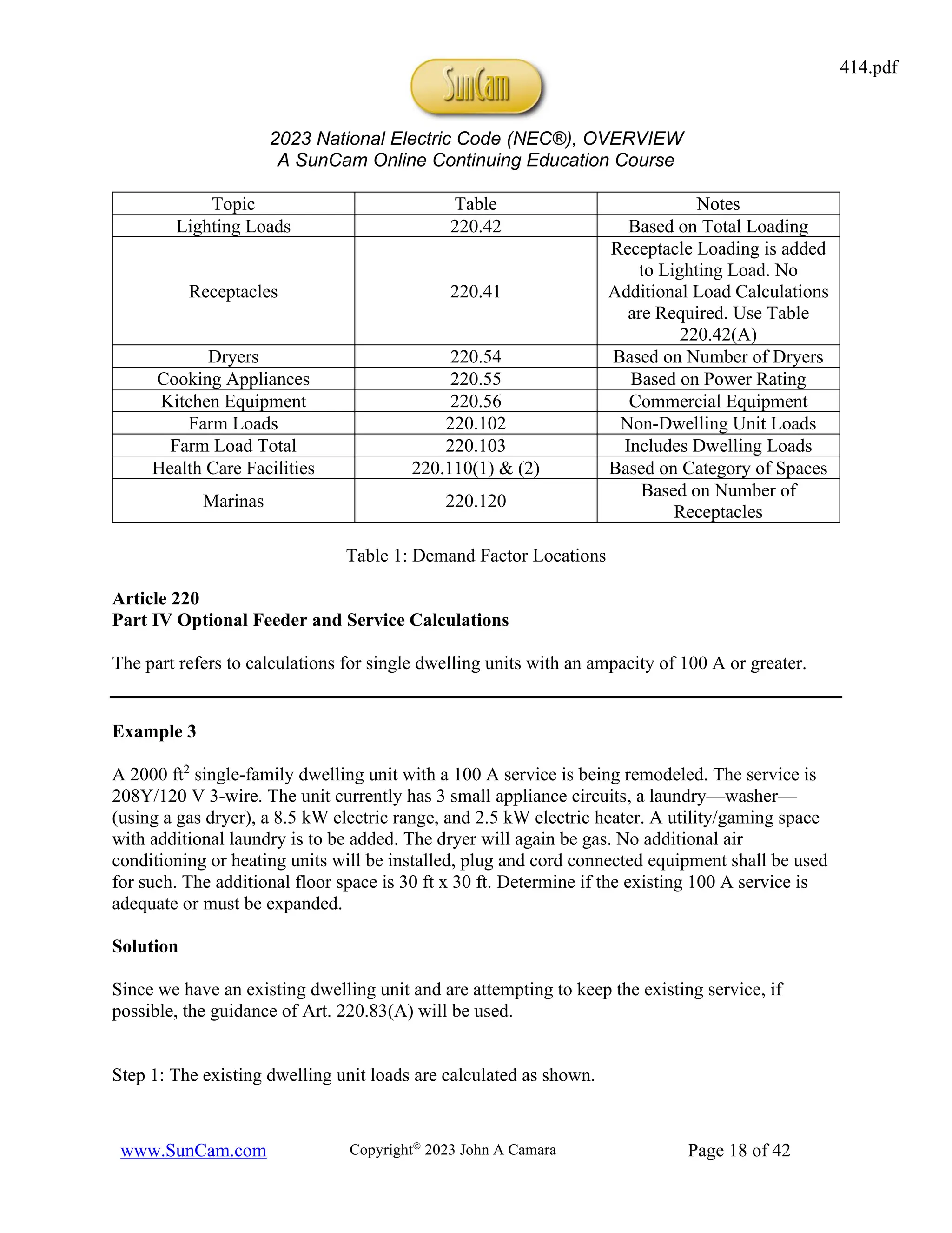
Step 2: Now, determine the additional load for the remodeling effort.
General Lighting [Art. 220.83(A)(1); 220.11; 220.14(J)]
414.pdf](https://image.slidesharecdn.com/414-240704194820-a10247cf/75/NEC-2023-NATIONAL-ELECTRICAL-DODE-2023-NEC-19-2048.jpg)
![2023 National Electric Code (NEC®), OVERVIEW
A SunCam Online Continuing Education Course
www.SunCam.com Copyright©
2023 John A Camara Page 20 of 42
SLighting
= PL
= 30 ft ´ 30 ft ´3
VA
ft2
= 2700 VA
Small Appliance Circuits [Art. 220.83(A)(2); 210.11(C)(1)—2 or more Circuits per
210.52(B)(1)—Previously Installed; 210.11(C)(2)—1 Laundry Circuit per 210.52(F);
Laundry Load per 220.52(B)]
SLaundry
= PSA
= 1 units ´1500
VA
unit
=1500 VA
The total additional load is the sum of the loads above.
STotal
= SL
+ SSA
= 2700 VA +1500 VA
= 4200 VA
Step 3: Determine the total load. Apply the demand factors for the total load. [Art. 220.83(A)]
STotal
= SExisting
+ SRemodel
= 23,000 VA + 4200 VA
= 27,200 VA
The demand factors are 100% for the first 8 kVA and 40% for the remainder.
STotal
= 1.0
( ) S8kVA
( )+ 0.4
( ) SRemainder
( )
= 1.0
( ) 8000 VA
( )+ 0.4
( ) 27,200 VA -8000 VA
( )
= 8000 VA + 7680 VA
= 15,680 VA
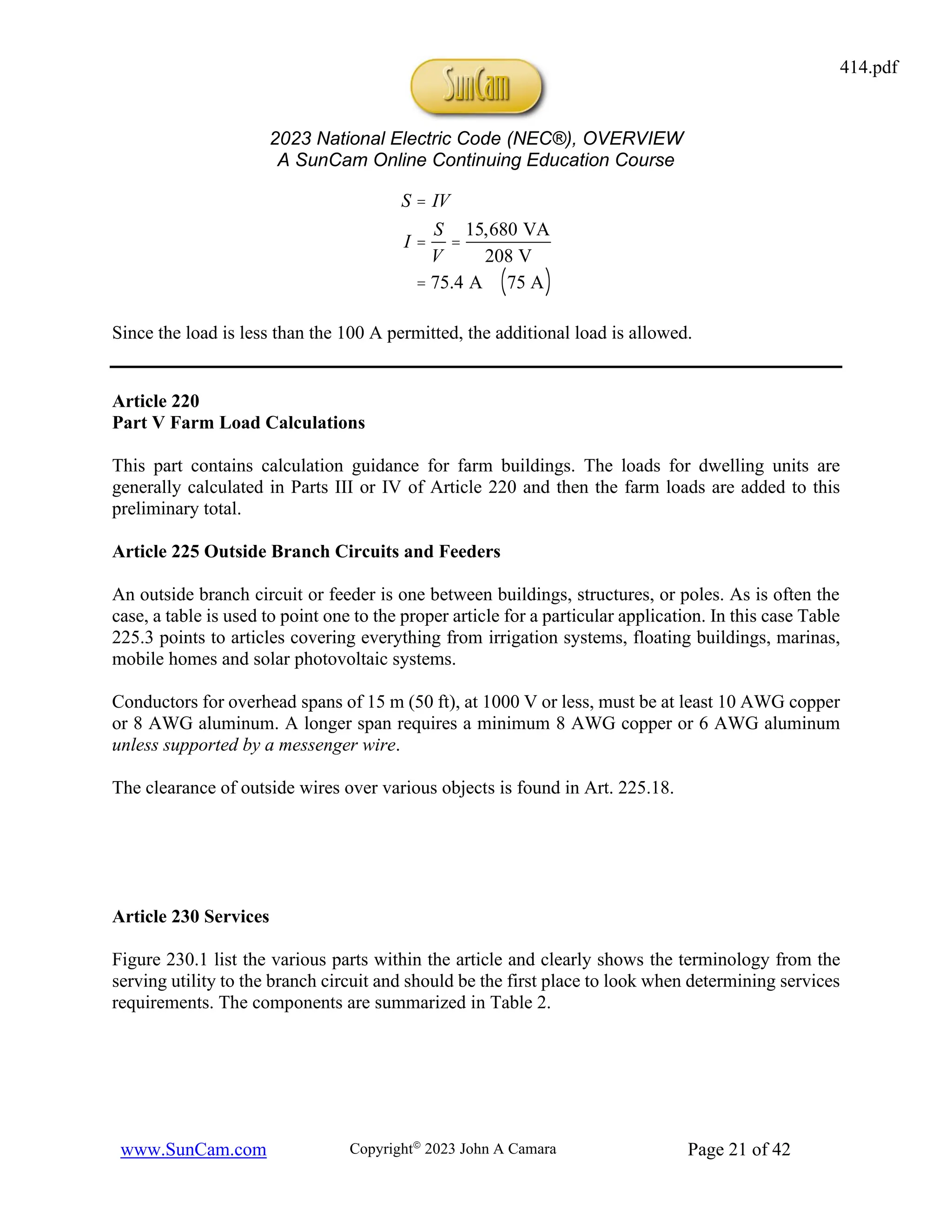
Step 4: Determine the current load for the entire 208 V system and compare to the 100 A
available. Round the answer up to be conservative.
414.pdf](https://image.slidesharecdn.com/414-240704194820-a10247cf/75/NEC-2023-NATIONAL-ELECTRICAL-DODE-2023-NEC-20-2048.jpg)
![2023 National Electric Code (NEC®), OVERVIEW
A SunCam Online Continuing Education Course
www.SunCam.com Copyright©
2023 John A Camara Page 32 of 42
part of the requirements of the NEC, but by listing them they clearly should be read and
understood. Figure 6 shows some battery terminology.18
Figure 6: Battery Standard Terminology
[Source: Power Reference Manual for the PE Exam]
480.2 Definitions
Nominal Voltage (Battery or Cell): The value assigned to a cell or battery for the purpose of
convenient designation. The operating voltage varies depending on a variety of factors.
Informational Note: Lead-Acid has a nominal cell voltage of 2 V/cell. Alkali systems have a
nominal of 1.2 V/cell. Li-ion cells, now in widespread use to due high energy density, have a
nominal voltage of 3.6 V/cell to 3.8 V/cell.
Example 7
A standard car battery is lead-acid and operates at approximately 12 V. Approximately how
many cells does the car battery contain?
Solution
Using 2 V/cell nominal gives the following number of cells.
18
Anode is from a Greek word meaning ascent, sometimes translated as high water. When Ben
Franklin performed his famous kite experiment, it appeared to him as if a cup was being filled to
overflow. He named those charges as positive and from that we get anode since current (water)
flows from high to low. Unfortunately, the sparks he observed were electrons, which were
discovered later and given the negative charge. So now, as engineers we learn that “conventional
current flows” from positive to negative (which it does inside the battery, hence the
anode/cathode designations) and positive to negative when discharging outside the battery, hence
the red cover on the cathode connection of the battery and the label +, and the black cable on the
anode connection of the cable and the label –.
414.pdf](https://image.slidesharecdn.com/414-240704194820-a10247cf/75/NEC-2023-NATIONAL-ELECTRICAL-DODE-2023-NEC-32-2048.jpg)

![2023 National Electric Code (NEC®), OVERVIEW
A SunCam Online Continuing Education Course
www.SunCam.com Copyright©
2023 John A Camara Page 40 of 42
Part III Grounding Methods
In 800.100(A)(3), which is also new, it specifies that a bonding conductor or grounding electrode
conductor cannot be smaller than 14 AWG nor does it have to be larger than 6 AWG. See
Informational Note Figure 800.100(B)(1) for a visual of the terminology.
There are many restrictions on where certain types of cables may be used be it horizontally,
vertically, under carpet, in a duct, in a raceway, air plenums, et cetera. See 800.154 and Tables
800.154(a), 800.154(b), and 500.154(c) for the many uses and restrictions.
Codes for the various cables are given in 800.179 and repeated in Table 4.
Cable Marking Type of Use
CMP Communications Plenum Cable
CMR Communications Riser Cable
CMG Communications General-Purpose Cable
CM Communications General-Purpose Cable
CMX Communications Limited Use
CMUC Communications Under-Carpet
Table 4: Communication Table Types
[Adapted from NEC 800.179]
Chapter 9 Tables
Chapter 9 is a mandatory part of the NEC. Since the metric system is worldwide with the exception
of the US, the tables for conduit list a metric trade designator and trade size. These can be found
in Table 300.1(C). For example, a ¾ inch conduit metric designator 21 and trade size ¾.
One of the more commonly used tables during construction or remodeling is Table 1 Percent of
Cross Section of conduit and tubing for Conductors and Cables. The remaining tables provide
the allowable fill for the different types of conduit. Since most conduit carries two or more wires,
the author recommends remembering one number from the table for immediate recall: 40%. That
is, for two or more wires in the conduit the area filled cannot exceed 40%.
General guidance, not part of the NEC itself is something called the jam ratio. The jam ratio is
defined as follows.
Rjam
=
IDraceway/conduit
ODconductor
414.pdf](https://image.slidesharecdn.com/414-240704194820-a10247cf/75/NEC-2023-NATIONAL-ELECTRICAL-DODE-2023-NEC-40-2048.jpg)


![Ebc codes[1]](https://cdn.slidesharecdn.com/ss_thumbnails/ebccodes1-140206134542-phpapp01-thumbnail.jpg?width=640&height=640&fit=bounds)


