Downloaded 152 times


![PRINCIPLES OF FOOD ENGINEERING Prepared By-Mohit Jindal Page 11 of 72
Viscosity is a resistance of a fluid which is being deformed by either shear stress or tensile
stress. In the other word we can say viscosity is the property of fluid by virtue of which is opposing its
flow.
Or
Viscosity is resistance to flow
Or
Viscosity describes a fluid's internal resistance to flow and may be thought of as a measure of
fluid friction.
Viscosity is an important characteristic of liquid foods in many areas of food processing. For
example the characteristic mouthfeel of food products such as tomato ketchup, cream, syrup and
yoghurt depends on their viscosity (or 'consistency'). The viscosity of many liquids changes during
heating/cooling or concentration and this has important effects on, for example, the power needed to
pump these products.
A liquid having a series of layers and when it flows over a surface, the uppermost layer flows
fastest and drags the next layer along at a slightly lower velocity, and so on through the layers. The
force that moves the liquid is known as the shearing force or 'shear stress' and the velocity gradient is
known as the 'shear rate'. If shear stress is plotted against shear rate, most simple liquids and gases
show a linear relationship and these are termed 'Newtonian' fluids. Examples include water, most oils,
gases, and simple solutions of sugars and salts. Where the relationship is non-linear the fluids are
termed 'non-Newtonian'. For all liquids, viscosity decreases with an increase in temperature but for
most gases it increases with temperature.(Lewis 1990).
In everyday terms (and for fluids only), viscosity is "thickness" or "internal friction".
Thus, water is "thin", having a lower viscosity, while honey is "thick", having a higher viscosity. All
real fluids have some resistance to stress and therefore are viscous. A fluid which has no resistance to
shear stress is known as an ideal fluid or in viscid fluid. Zero viscosity is observed only at very low
temperatures, in super fluids.
The word "viscosity" is derived from the Latin "viscum", meaning mistletoe and also a
viscous glue (birdlime) made from mistletoe berries. Viscosity represented by the symbol η "eta".
Viscosity is the ratio of the tangential frictional force per unit area. The SI unit of viscosity is
the pascal second [Pa s]. The pascal second is rarely used today the most common unit of viscosity is
the dyne second per square centimeter [dyne s/cm2], which is given the name poise [P] after the French
physiologist Jean Poiseuille (1799–1869). Ten poise equal one pascal second [Pa s] making
the centipoise [cP] and millipascal second [mPa s] identical.
1 pascal second = 10 poise
1 pascal second = 1,000 millipascal second
1 centipoise = 1 millipascal second
The other quantity called kinematic viscosity (represented by the symbol ν "nu") is the ratio of
the viscosity of a fluid to its density. The SI unit of kinematic viscosity is the square meter per
second [m2/s]. A more common unit of kinematic viscosity is the square centimeter per second [cm2/s],
which is given the name stokes [St] after the Irish mathematician and physicist George Stokes (1819–
1903).
1 m2/s = 10,000 cm2/s [stokes]
1 m2/s = 1,000,000 mm2/s [centistokes]](https://image.slidesharecdn.com/pfecompletebookfinal-190130125550/85/PRINCIPLES-OF-FOOD-ENGINEERING-11-320.jpg)


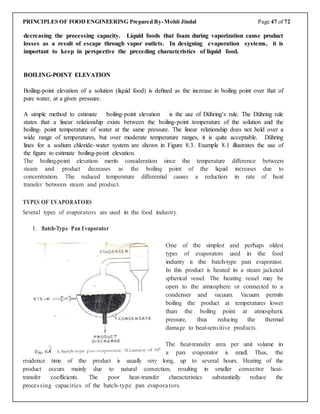
![PRINCIPLES OF FOOD ENGINEERING Prepared By-Mohit Jindal Page 37 of 72
Consider this example:
For example, if you open a bottle of highly volatile material such as nail polish remover in a room, the
component (acetone) will migrate to various parts of the room because of the concentration gradients
of acetone. If the air is stationary, the transfer occurs as a result of random motion of the acetone
molecules. If a fan or any other external means are used to cause air turbulence, the eddy currents will
enhance the transfer of acetone molecules to distant regions in the room.
All three of the molecular transport processes - momentum, heat, and mass-are characterized by the
general type of equation,
In mass transfer, mass is transferred under the driving force provided by a partial pressure or
concentration difference. The rate of mass transfer is proportional to the potential (pressure or
concentration) difference and to the properties of the transfer system characterized by a mass-transfer
coefficient.
Mass transfer coefficient: - In engineering, the mass transfer coefficient is a diffusion rate constant that
relates the mass transfer rate, mass transfer area, and concentration change as driving force:
Where:
kc is the mass transfer coefficient [mol/(s·m2)/(mol/m3)], or m/s
is the mass transfer rate [mol/s]
A is the effective mass transfer area [m2]
ΔCA is the driving force concentration difference [mol/m3].
Types of mass transfer :-
Mass transfer involves both mass diffusion occurring at a molecular scale and bulk transport of mass
due to convection flow.
1. Diffusion mass transfer
2. Convection mass transfer
1. Diffusion mass transfer
1) Molecular diffusion
2) Eddy diffusion
Molecular diffusion: - Diffusion from the random molecular motion is termed molecular
diffusion. It is the transfer of matter on a microscopic level from a region of higher conc. to
lower conc. i.e. mixing of gas and liquid. Molecular diffusion is four types:-
1. Ordinary diffusion: - Result from the conc. gradient (higher to lower). The diffusion sub-stance
to moves from a position of lower conc.
2. Thermal diffusion: - Due to different in temperature from one part to another in the system .A
temperature gradient will develop which cause diffusion.
3. Pressure diffusion: - Resulting from the atmospheric pressure differences that provide the
driving potential to the mass transfer.
4. Forced diffusion: - This is result due to external force.](https://image.slidesharecdn.com/pfecompletebookfinal-190130125550/85/PRINCIPLES-OF-FOOD-ENGINEERING-37-320.jpg)

![PRINCIPLES OF FOOD ENGINEERING Prepared By-Mohit Jindal Page 39 of 72
the left will have moved to the right, and 20% of the molecules moved from right to left. Now we
count the molecules on each side, then, we will find 8 ``x'' molecules remaining on the left and 2 on the
right, and 16 ``y'' molecules remaining on the right, 4 having moved to the left. If we assume that the
mass of each molecule is 1 unit, we can calculate concentrations in units of mass/volume. Thus, we
obtain Fick's Law:
Or
Where
J is the "diffusion flux" (amount of substance) per unit area per unit time]. J measures the
amount of substance that will flow through a small area during a small time interval.
mg is mass flux of component B (kg/s)
c is the concentration of component B, mass per unit volume (kg/m 3)
D is the mass diffusivity (m 2/s);
A is area (m 2).
x is the position [length], for example m.
We note that Fick’s law is similar to Fourier’s law of heat conduction,
Where
q is the rate of heat flow in the direction of heat transfer by conduction (W)
k is thermal conductivity (W/[m °C])
A is area (normal to the direction of heat transfer) through which heat flows (m 2);
T is temperature (°C); and x is length (m), a variable.
and Newton’s equation for shear-stress–strain relationship,
These similarities between the three transport equations suggest additional analogies among mass
transfer, heat transfer, and momentum transfer.](https://image.slidesharecdn.com/pfecompletebookfinal-190130125550/85/PRINCIPLES-OF-FOOD-ENGINEERING-39-320.jpg)


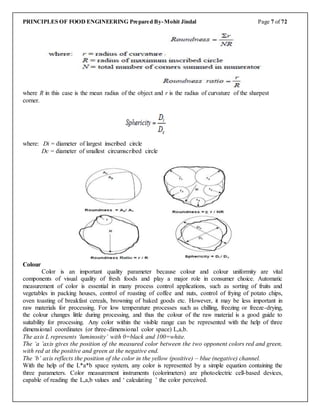
The document outlines the principles of food engineering, covering essential topics such as units of measurement, material and energy balance, fluid mechanics, heat and mass transfer, and thermal processing of foods. It also details practical applications, including the determination of physical properties of food materials and the analysis of equipment used in food processing. Furthermore, it discusses various physical properties relevant to food quality and engineering, emphasizing the importance of rheological, mechanical, thermal, electrical properties, and specific measurements like density and porosity.


