Soil Mechanics; Falling Head Permeability Test Presentation
This presentation discusses the objectives, procedures and significance of a falling head permeability test. It also entails how to read and interpret the results of a test conducted in a laboratory
CONCEPT OF
PERMEABILITY
Permeabilityis the ability of soil to transmit water through
the soil voids or pores.
The fallen head permeability test(is also known as the variable
head test) is a test used to determine the level of
permeability of fine-grained soils such as clay and silt, usually
it is suitable for soils with low or less level of
permeability(hydraulic conductivity).
The falling head permeability test is a common laboratory
testing method used to determine the permeability of finely
grained soils with intermediate and low permeability such as
silts and clays. This testing method can be applied to an
undisturbed sample and disturbed soil samples.
3.
OBJECTIVE
The primaryobjective of this experiment is to determine the
permeability of a soil sample the usage of the steady-head
method and to calculate the coefficient of permeability for
the given pattern.
4.
RELEVANCE
OF THE TEST
Helps in estimating soil water retention properties.
Important in foundation design, seepage analysis, and
drainage planning.
To assess the settlement rates of structures
Evaluating the stability of slopes.
Predicting how water flows through soil.
5.
TEST
DESCRIPTIO
N AND
PROCEDURE
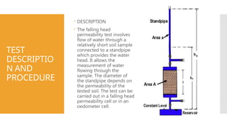
DESCRIPTION
The falling head
permeability test involves
flow of water through a
relatively short soil sample
connected to a standpipe
which provides the water
head. It allows the
measurement of water
flowing through the
sample. The diameter of
the standpipe depends on
the permeability of the
tested soil. The test can be
carried out in a falling head
permeability cell or in an
oedometer cell.
PROCEDURE
Soil Preparation:
Dryand sieve the soil
sample with a 4.75 mm
sieve.
Permeameter Assembly:
Set up the permeameter
and fill the constant head
tank with water.
Soil Placement:
Place the soil sample into
the permeameter and
compact it to the desired
density.
8.
PROCEDURE
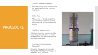
Constant HeadMaintenance:
Keep a constant head by adjusting
the water height in the constant
head tank.
Water Flow:
Allow water to flow through the
soil sample for a specific period,
measuring the accumulated water
volume
Head Loss Measurement:
Calculate the water pressure lost by
measuring the difference in water
level between the entrance and exit
of the permeameter.
Coefficient of Permeability
Calculation:
Using the Darcy’s law to calculate
the coefficient of permeability (k). or
the fallen head equation
9.
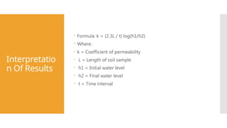
Interpretatio
n Of Results
Formula: k = (2.3L / t) log(h1/h2)
Where:
k = Coefficient of permeability
L = Length of soil sample
h1 = Initial water level
h2 = Final water level
t = Time interval
10.
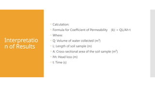
Interpretatio
n of Results
Calculation:
Formula for Coefficient of Permeability (k): = QL/Ah t
⋅
Where:
Q: Volume of water collected (m³)
L: Length of soil sample (m)
A: Cross-sectional area of the soil sample (m²)
ℎh: Head loss (m)
t: Time (s)
11.
EXAMPLE
CALCULATIO
N
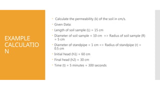
Calculate thepermeability (k) of the soil in cm/s.
Given Data:
Length of soil sample (L) = 15 cm
Diameter of soil sample = 10 cm => Radius of soil sample (R)
= 5 cm
Diameter of standpipe = 1 cm => Radius of standpipe (r) =
0.5 cm
Initial head (h1) = 60 cm
Final head (h2) = 30 cm
Time (t) = 5 minutes = 300 seconds
12.
CALCULATIO
N C’TD
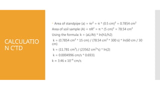
Areaof standpipe (a) = πr² = π * (0.5 cm)² = 0.7854 cm²
Area of soil sample (A) = πR² = π * (5 cm)² = 78.54 cm²
Using the formula: k = (aL/At) * ln(h1/h2)
k = (0.7854 cm² * 15 cm) / (78.54 cm² * 300 s) * ln(60 cm / 30
cm)
k = (11.781 cm³) / (23562 cm²*s) * ln(2)
k = 0.0004996 cm/s * 0.6931
k ≈ 3.46 x 10⁻⁴ cm/s
13.
CONCLUSIO
N
From thetest, the coefficient of permeability of the soil
sample is determined. These outcomes are valuable for
designing drainage systems and predicting the steadiness
of soil slopes.
14.
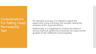
Considerations
For Falling Head
Permeability
Test
For elevated accuracy, it is helpful to repeat the
experiment using numerous soil samples, taking the
common of the acquired effects.
Additionally, It is suggested to conduct the check at
various hydraulic gradients to evaluate the impact of the
gradient at the coefficient of permeability.
15.
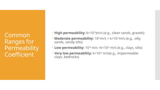
Common
Ranges for
Permeability
Coefficient
Highpermeability: k>10-4
)m/s (e.g., clean sands, gravels)
Moderate permeability: 10-6
m/s < k<10-4
m/s (e.g., silty
sands, sandy silts)
Low permeability: 10-8
m/s <k<10-6
m/s (e.g., clays, silts)
Very low permeability: k<10-8
m/s(e.g., impermeable
clays, bedrocks)


![Geotechnical Engineering-I [Lec #24: Soil Permeability - II]](https://cdn.slidesharecdn.com/ss_thumbnails/24-180924141149-thumbnail.jpg?width=640&height=640&fit=bounds)


