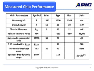
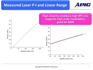
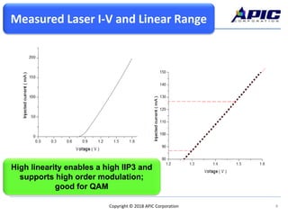
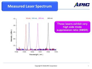
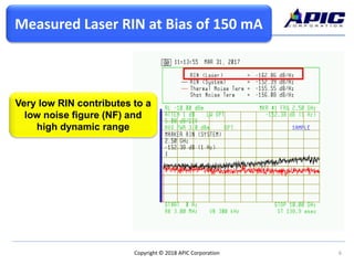
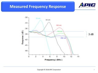
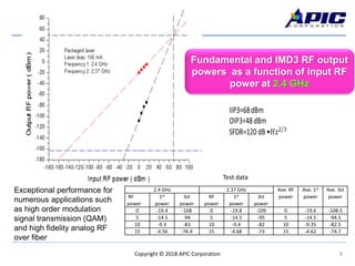
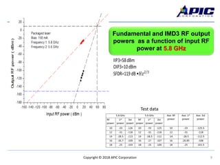
1Copyright © 2018 APIC Corporation
APIC’s Direct Modulated
DFB Laser Performance
2Copyright © 2018 APIC Corporation
Measured Chip Performance
Main Parameters Symbol Min. Typ. Max. Units
Wavelength λ λ 1530 1550 1565 nm
Output power P 50 60 70 mW
Threshold current 𝑰 𝒕𝒉 9 10 12 mA
Relative intensity noise RIN -160 -150 dB/Hz
Side-mode suppression
ratio
SMSR 35 50 dB
3 dB band width 𝒇 𝟑𝒅𝑩 𝒇 𝟑𝒅𝑩 10 GHz
Third order intercept
point
IIP3 35 40 dBm
Spurious-free dynamic
range
SFDR 119
Measured Chip Performance
3Copyright © 2018 APIC Corporation
Measured Laser P-I and Linear Range
High linearity enables a high IIP3 and
supports high order modulation;
good for QAM
Measured Laser P-I and Linear Range
4Copyright © 2018 APIC Corporation
Measured Laser I-V and Linear RangeMeasured Laser I-V and Linear Range
High linearity enables a high IIP3 and
supports high order modulation;
good for QAM
5Copyright © 2018 APIC Corporation
Measured Laser Spectrum
These lasers exhibit very
high side mode
suppression ratio (SMSR)
6Copyright © 2018 APIC Corporation
Measured Laser RIN at Bias of 150 mA
Very low RIN contributes to a
low noise figure (NF) and
high dynamic range
7Copyright © 2018 APIC Corporation
3 dB
Measured Frequency Response
8Copyright © 2018 APIC Corporation
2.4 GHz 2.37 GHz Ave. RF
power
Ave. 1st
power
Ave. 3st
powerRF
power
1st
power
3st
power
RF
power
1st
power
3st
power
0 -19.4 -108 0 -19.8 -109 0 -19.6 -108.5
5 -14.5 -94 5 -14.5 -95 5 -14.5 -94.5
10 -9.3 -83 10 -9.4 -82 10 -9.35 -82.5
15 -4.56 -76.4 15 -4.68 -73 15 -4.62 -74.7
Test data
Exceptional performance for
numerous applications such
as high order modulation
signal transmission (QAM)
and high fidelity analog RF
over fiber
Fundamental and IMD3 RF output
powers as a function of input RF
power at 2.4 GHz
9Copyright © 2018 APIC Corporation
Test data
Fundamental and IMD3 RF output
powers as a function of input RF
power at 5.8 GHz
10Copyright © 2018 APIC Corporation
APIC Corporation
5800 Uplander Way
Culver City CA 90230
(310) 642-7975
sales@apichip.com
www.apichip.com
https://www.linkedin.com/company/apic-corp/
Bob Walter
Director Pgm. Mgt.
walter@apichip.com
Yi-Guang Zhao
Director of Engineering
Sr. Photonics Engineer
zhao@apichip.com
Koichi Sayano
VP of Optical Systems
Sr. Systems Engineer
sayano@apichip.com

Performance of APIC's Direct Modulated DFB Lasers

  • 1.
    1Copyright © 2018APIC Corporation APIC’s Direct Modulated DFB Laser Performance
  • 2.
    2Copyright © 2018APIC Corporation Measured Chip Performance Main Parameters Symbol Min. Typ. Max. Units Wavelength λ λ 1530 1550 1565 nm Output power P 50 60 70 mW Threshold current 𝑰 𝒕𝒉 9 10 12 mA Relative intensity noise RIN -160 -150 dB/Hz Side-mode suppression ratio SMSR 35 50 dB 3 dB band width 𝒇 𝟑𝒅𝑩 𝒇 𝟑𝒅𝑩 10 GHz Third order intercept point IIP3 35 40 dBm Spurious-free dynamic range SFDR 119 Measured Chip Performance
  • 3.
    3Copyright © 2018APIC Corporation Measured Laser P-I and Linear Range High linearity enables a high IIP3 and supports high order modulation; good for QAM Measured Laser P-I and Linear Range
  • 4.
    4Copyright © 2018APIC Corporation Measured Laser I-V and Linear RangeMeasured Laser I-V and Linear Range High linearity enables a high IIP3 and supports high order modulation; good for QAM
  • 5.
    5Copyright © 2018APIC Corporation Measured Laser Spectrum These lasers exhibit very high side mode suppression ratio (SMSR)
  • 6.
    6Copyright © 2018APIC Corporation Measured Laser RIN at Bias of 150 mA Very low RIN contributes to a low noise figure (NF) and high dynamic range
  • 7.
    7Copyright © 2018APIC Corporation 3 dB Measured Frequency Response
  • 8.
    8Copyright © 2018APIC Corporation 2.4 GHz 2.37 GHz Ave. RF power Ave. 1st power Ave. 3st powerRF power 1st power 3st power RF power 1st power 3st power 0 -19.4 -108 0 -19.8 -109 0 -19.6 -108.5 5 -14.5 -94 5 -14.5 -95 5 -14.5 -94.5 10 -9.3 -83 10 -9.4 -82 10 -9.35 -82.5 15 -4.56 -76.4 15 -4.68 -73 15 -4.62 -74.7 Test data Exceptional performance for numerous applications such as high order modulation signal transmission (QAM) and high fidelity analog RF over fiber Fundamental and IMD3 RF output powers as a function of input RF power at 2.4 GHz
  • 9.
    9Copyright © 2018APIC Corporation Test data Fundamental and IMD3 RF output powers as a function of input RF power at 5.8 GHz
  • 10.
    10Copyright © 2018APIC Corporation APIC Corporation 5800 Uplander Way Culver City CA 90230 (310) 642-7975 sales@apichip.com www.apichip.com https://www.linkedin.com/company/apic-corp/ Bob Walter Director Pgm. Mgt. walter@apichip.com Yi-Guang Zhao Director of Engineering Sr. Photonics Engineer zhao@apichip.com Koichi Sayano VP of Optical Systems Sr. Systems Engineer sayano@apichip.com