1. 4
SeeWave®I Interference Locating System
2 Host ~Iatform
lJl, I-
(((~)l lL
UJ
. ..... Z
UJ
[!J
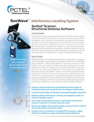
SeeGull" Scanner,
Directional Antenna, Software
CHALLENGE:
Interference impacts network performance. On 4G LTE network deploy-
ments. the effects of interference may include significantly reduced
throughput rates. Interferers discovered in new spectrum allocations
and the re-farming of existing bands also threatens network quality.
Potential sources of interference are too numerous to count, from
fluorescent lights to garage door openers to unlicensed radio signals.
Detecting and locating the exact position of these interferers can be
expensive and time-consuming, often depending on equipment that can
be cumbersome and difficult for one person to operate efficiently.
SOLUTION:
PCTELS SeeWave is the comprehensive tool for a single user to accurately
detect the interfering frequency and locate its exact source. SeeWave
utilizes PCTEL!s leading edge SeeGull® scanning receiver. A host
platform links the scanner to both a direction-finding antenna and a
touchscreen tablet. The platform can be held comfortably in one hand
while the user operates SeeWave's intuitive software application.
Scanning receiver, host platform, antenna, and tablet-optimized software
combine to create an economical, easy-to-use, and highly effective
interference hunting system. It uses advanced spectrum analysis and
proprietary algorithms to both identify harmful interference and locate
its source. This saves effort, time, and cost for mobile operators working
to eliminate interference and maximize network Quality of Service.
Enhance network performance by identifying numerous types of
interfering signals with advanced spectrum analysis measurements
Locate the exact position of interference through triangulation algorithms
Identify problems efficiently by collecting and analyzing results in a
variety of playback options
Clear uplink and downlink channels on select bands and spectrum
ranges for spectrum re-farming using dual scans
Reduce user fatigue with ergonomic design, using one hand to hold the
unit and the other to operate the tablet
Increase return on investment of existing PCTEL scanners, adding
interference finding to a range of network testing applications
==---------------------"'''1,'''-
/
2. UL
DL
| 2 |
SeeWave | Features
“Interference Hunting Evolved”
SeeWave Software Application
Intuitive touchscreen interface with
a simple workflow
Numerous charting options to quickly
identify interfering sources
Simplified open street based
mapping and triangulation
functionality
SeeWave Hardware
Host platform connects the
scanning receiver to the antenna
and tablet-controlled software
Ergonomic and lightweight design
for one hand operation
Includes digital compass and
pre-amplifier for accurate
direction finding
SeeWave Scanning Receivers and Walk Test Kit
Utilizes PCTEL’s scanning receivers equipped with
advanced spectrum analyzer and Enhanced Power Scan
Interference locating function adds to scanners’
testing applications across the network
life cycle and boosts ROI
..
J
. r"·":
---------------------~
3. Scan Setup
Scan settings set up by E-UTRA
band or custom selected range compatible
with connected SeeGull scanner
Start, Stop, Center Frequency, Span and Resolution
Bandwidth determines initial scanning parameters
Allows for two independent scans at any time for
parallel scanning and data collection
Maps
Digital compass displays antenna direction
GPS displays user’s exact location on map
User option of manual or automatic mode to select
directional bearing of interferer
Triangulate based on multiple user-selected bearings
Industry-unique capability for TD-LTE triangulation
Spectrum Charts
Trace displays real time, average,
maximum, and minimum power levels
Touch-and-drag adjustable
Selected Frequency Marker determines the
directional bearings for mapping
Simultaneous scans
Spectrogram
Waterfall depicts chronological, linear visual
representation of the scan power levels
Spot patterns and identify intermittent
interference signals even when not shown
on a live spectrum chart
| 3 |
SeeWave | Software
4. 200 MHz to 6 GHz
0.9W with Preamplifier On
7.3”D x 8.5” W x 10.5”H (185.4 mm D x 216 mm W x 267 mm H)
with 8” tablet mounted
Preamplifier Bandwidth
Maximum Power
Size
1.2 lb (0.53 kg) includes cablesWeight
Weight
Preamplifier Gain 200 MHz – 2.7 GHz
2.7 GHz – 4.5 GHz
4.5 GHz – 6.0 GHz
Bypass: 0 dB Step 1: 9 dB Steps 1 & 2: 25 dB
0 dB 6 dB 20 dB
0 dB 4 dB 15 dB
RF Connector
Safety (CE)
EMC
Shock and Vibration
Tripod Mount
Temperature Range
N Male
Cables (to Walk Test Kit) 50” (1.3 m) Length
Operating: -10°C to +50°C; Storage: -40°C to +85°C
EN 60950-1
EN 301 489-1
MIL-STD-810G, SAE J1455
RoHS Compliant (6/6)
¼ – 20 UNC x 7 mm
0, 10, 20, 30 dBAttenuation Steps
Refer to MXflex, IBflex, EXflex, MX, or EX Family Specifications
<= 5 deg, nominalDigital Compass Accuracy
GPS
PREAMPLIFIER/AT TENUATOR
DIGITAL COMPASS AND GPS
PHYSICAL
17.7” L x 9” W (450 mm L x 229 mm W)
OP409 Antenna, 690 MHz – 6 GHz Log Periodic
Size
1.3 lb (0.59 kg)
Gain
RF Connector N Female
8 dBd
Weight
13.8” L x 5.9” W (350 mm L x 149 mm W)Size
0.8 lb (0.4 kg)
Gain
RF Connector N Female
6.5 dBd
DIRECTIONAL ANTENNAS
Weight
22” L x 13.2” W (558 mm L x 335 mm W)
OP410 Antenna, 440 MHz – 480 MHz Yagi
Size
1.2 lb (0.54 kg)
Gain
RF Connector N Female
6.5 dBd
OP436 Antenna, 690 MHz – 6 GHz Log Periodic
| 4 |
SeeWave | Specifications
Please contact your sales representative or email seewave@pctel.com for more details
or to request an informative poster on RF Interference.
QMS Certified ISO 9001:2008
10MRK6-03 RevC March 2016
Specifications subject to change without notice.
P C T E L, I n c. R F S o l u t i o n s
2 0 4 1 0 O b s e r v a t i o n D r i v e S u i t e 2 0 0
G e r m a n t o w n M a r y l a n d U S A 2 0 8 7 6
rfsolutions.pctel.com p +1 301 515 0036 | f +1 301 515 0037
.....
-
v
t::---~
~
r:;..,.,
[k'"
' !~
r ~
---- =