Download to read offline

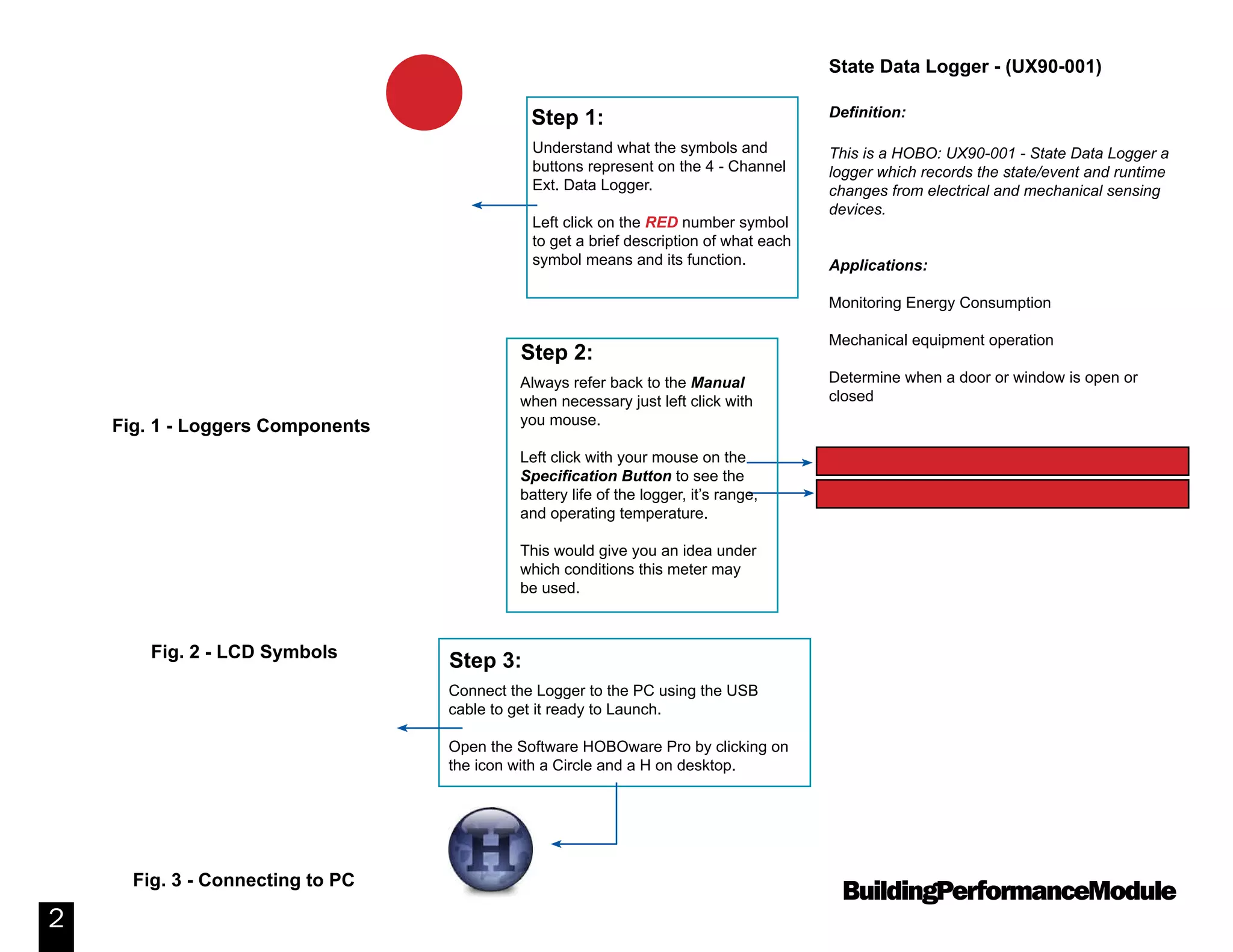
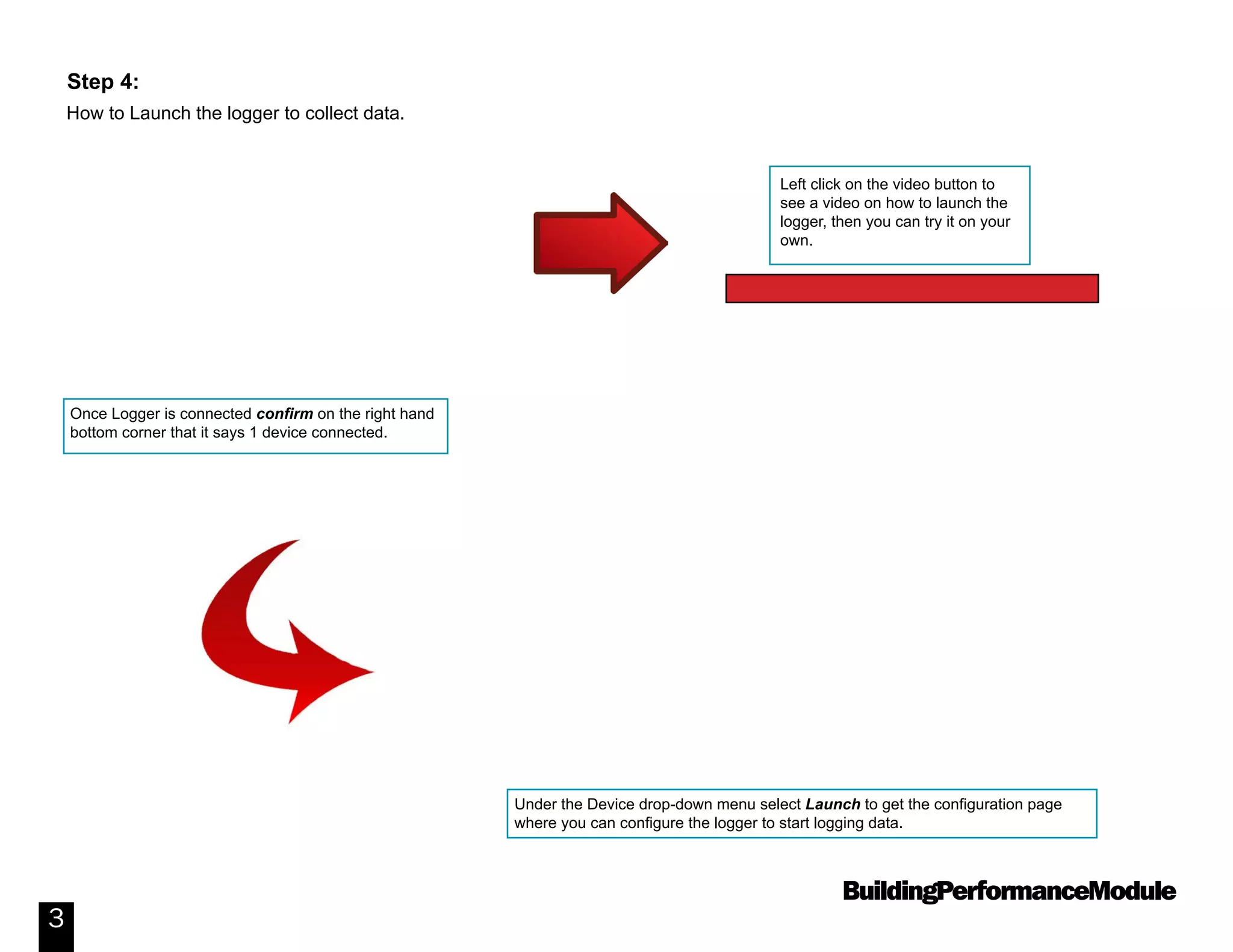

This document provides instructions for using the HOBO UX90-001 State Data Logger. It describes the logger's components and specifications. It then provides step-by-step instructions for launching the logger to begin collecting data, checking its status, placing it to monitor a electrical panel, reading out the collected data, viewing the graph created in HOBOware software, and exporting the data to a CSV file for further analysis in Excel. Additional resources are referenced for learning more about using the HOBOware Pro software.