1) The document discusses the design and analysis of an engine that runs on compressed air for vehicles. It aims to reduce pollution by using compressed air instead of gasoline or diesel.
2) The engine was tested on a kinetic K4 100cc petrol engine by modifying the camshaft to open and close the intake and exhaust valves simultaneously to allow continuous flow of compressed air. This allowed the vehicle to run at up to 30kph.
3) Compressed air vehicles have potential advantages of being lightweight, cheap to operate, safe for flammable environments, and zero emissions. However, challenges remain in increasing their performance and range. Several companies are working to develop compressed air cars commercially.
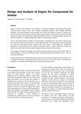


![Bore x Stroke : 50.0 x 49.50 mm 4. K'Airmobiles vehicles, France
Fuel Type : Petrol 5. Engine-air company, Australian
Starter : Kick 6. Honda Air concept car.
Fig. 5: Kinetic K4 Engine
In this experiment, as observed does not contain any
type of fuel, working only on compressed air. It
requires some changes in lobs of cam shaft. Initially,
the lobs were present at 60 degrees apart from each
other, which turned to 180 degree to each other. It
means when the inlet valve is open, the outlet valve
remain closed and vice-versa, so that expansion of
compressed air inside cylinder can take place easily.
The quantity of pressurized air in engine could be
maintained with the help of accelerator. Here, the
engine could be start with the help of kick only. The
compressed air is supplied continuously, but no air
will be wasted. The engine also consists of gear
mechanism, containing four gears, which can be
used at varied payload and speed.
Manufacturing and developments
Various companies are investing in the research,
development and deployment of compressed air
cars. Overoptimistic reports of impending production
date back to at least May 1999. Most of the cars
underdevelopment also rely on using similar
technology to low-energy vehicles in order to
increase the range and performance of their cars.
Here is a brief list of few leading manufacturers who
are putting their concerted efforts towards making
compressed air vehicle a reality for public us .
1. Motor Development International, France
2. Tata Motors, India
3. The Energine Corporation, a South Korean
company
Expected outcomes
The following points could be the expected
outcomes of compressed air engine are:
1. Light weight of compressed air vehicle.
2. Easy to transport.
3. Easy to handle.
4. Cheaper in cost.
5. Able to work in drastic/critical flammable areas.
6. No ignitions of any fuel.
7. Eco-friendly, No emission of any type of
pollution and pollutant.
References
[1] Saurabh pathak, compressed air vehicle: a review,
Proceedings of 4th IRF International Conference, Chennai,
9th March-2014, ISBN: 978-93-82702-64-1
[2] Nitin Parashar, Syed Mazhar Ali, Sumit Chauhan, Ravi
Saini : Design and Analysis of Compressed Air Engine.
International Journal of Engineering Research &
Technology (IJERT) ISSN: 2278-0181 Vol. 3 Issue 6, June -
2014
[3] Haisheng Chen et al. "Air fuelled zero emission road
transportation: A comparative study" Applied Energy 88
(2011), 24 June 2010, pp: 337-342
[4] Mistry Manish K. Study and development of
compresswd air engine single cyinder: a review study,
International Journal of Advanced Engineering Technology
E-ISSN 0976-3945
[5] Arjit Mourya, Modified Compressed Air Engine Two
stroke engine working on the design of a four stroke
petrol engine, ISSN (Print): 2319-3182, Volume -3, Issue-4,
2014.
[6] J P Yadav and Bharat raj singh, Study and Fabrication of
Compressed Air Engine, copyright samriddhi, 2011 S-JPSET
: ISSN : 2229-7111, Vol. 2, Issue 1.
[7] S. S. Verma, Latest Developments of a Compressed Air
Vehicle: A Status Report, Global Journal of Researches in
Engineering Automotive Engineering Volume 13 Issue 1
Version 1.0 Year 2013.
Author's details
1
Research Scholar,
2,3
Assistant Professor, MIT, Bhopal, M.P.,
Email: Raj860222@gmail.com, rajkushwah42@yahoo.com](https://image.slidesharecdn.com/p-12-230328095847-76c76b56/85/P-12-docx-5-320.jpg)


