Downloaded 17 times
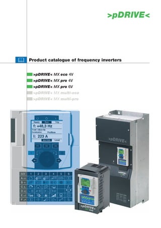


![>pDRIVE< MX pro 6V
General technical data
Mains voltage 3-phase 500V -15% … 690V+10%; 50/60Hz+/-5%
P1: 150 % for 60 s per 10 minutes, 165 % for 2 seconds
Maximum current
P2: 120 % for 60 s per 10 minutes, 135 % for 2 seconds
Built in unit with protection degree IP20, from 90/110 kW IP20 / IP00
Design
Wall-mounting device with protection degree IP41/IP21, from 90/110 kW IP31
P1: -10...+50°C, up to +60°C with derating
Operating temperature
P2: -10...+45°C, up to +55°C with derating
Removable matrix operating panel, extensible terminals, speed feedback,
Interfaces
RS 485 / Modbus, Profibus DP, CANopen
RFI filter built-in for 2nd "industrial environment" category C3
Special functions braking unit built-in up to 160/200 kW, above as option
function "Safe Standstill" according to EN 954-1 / ISO 13849-1 category 3
Standards CE, UL, CSA, GOST, ATEX
Motor output Output current
Dimensions
>pDRIVE< (500 V P1/P2) (500 V P1/P2) Order code 1.)
W x H x D [mm]
690 V P1/P2 690 V P1/P2
MX pro 6V2,2/3,0 (1.5/2.2) 2.2/3.0 kW (3.2/4.5) 4.0/4.5 A 240 x 420 x 236 MP6U22AAB
HUSI
MX pro 6V3,0/4,0 (2.2/3.0) 3.0/4.0 kW (4.5/5.8) 4.5/5.5 A 240 x 420 x 236 MP6U30AAB
MX pro 6V4,0/5,5 (3.0/4.0) 4.0/5.5 kW (5.8/7.5) 5.5/7.5 A 240 x 420 x 236 MP6U40AAB
MX pro 6V5,5/7,5 (4.0/5.5) 5.5/7.5 kW (7.5/10) 7.5/10 A 240 x 420 x 236 MP6U55AAB
MX pro 6V7,5/11 (5.5/7.5) 7.5/11 kW (10/13.5) 10/13.5 A 240 x 420 x 236 MP6U75AAB
MX pro 6V11/15 (7.5/11) 11/15 kW (13.5/18.5) 13.5/18.5 A 240 x 420 x 236 MP6D11AAB
8 P01 002 EN.05/05
MX pro 6V15/18 (11/15) 15/18 kW (18.5/24) 18.5/24 A 240 x 420 x 236 MP6D15AAB
MX pro 6V18/22 (15/18) 18/22 kW (24/29) 24/27 A 240 x 420 x 236 MP6D18AAB
MX pro 6V22/30 (18/22) 22/30 kW (29/35) 27/35 A 240 x 420 x 236 MP6D22AAB
MX pro 6V30/37 (22/30) 30/37 kW (35/47) 35/43 A 320 x 630 x 290 MP6D30AAB
MX pro 6V37/45 (30/37) 37/45 kW (47/59) 43/54 A 320 x 630 x 290 MP6D37AAB
MX pro 6V45/55 (37/45) 45/55 kW (59/68) 54/62 A 320 x 630 x 290 MP6D45AAB
MX pro 6V55/75 (45/55) 55/75 kW (68/85) 62/84 A 320 x 630 x 290 MP6D55AAB
MX pro 6V75/90 (55/75) 75/90 kW (85/110) 84/104 A 320 x 630 x 290 MP6D75AAB
MX pro 6V90/110 (75/90) 90/110 kW (110/136) 104/125 A 330 x 950 x 377 MP6D90AAB
MX pro 6V110/132 (90/110) 110/132 kW (136/165) 125/150 A 330 x 950 x 377 MP6C11AAB
MX pro 6V132/160 (110/132) 132/160 kW (165/200) 150/180 A 330 x 950 x 377 MP6C13AAB
MX pro 6V160/200 (132/160) 160/200 kW (200/240) 180/220 A 330 x 950 x 377 MP6C16AAB
MX pro 6V200/250 (160/200) 200/250 kW (240/312) 220/290 A 585 x 950 x 377 MP6C20AAA 2.)
MX pro 6V250/315 (200/250) 250/315 kW (312/390) 290/355 A 585 x 950 x 377 MP6C25AAA 2.)
MX pro 6V315/400 (250/315) 315/400 kW (390/462) 355/420 A 585 x 950 x 377 MP6C31AAA 2.)
MX pro 6V400/500 (315/400) 400/500 kW (462/590) 420/543 A 1110 x 1150 x 377 MP6C40AAA 2.)
MX pro 6V500/630 (400/500) 500/630 kW (590/740) 543/675 A 1110 x 1150 x 377 MP6C50AAA 2.)
MX pro 6V630/800 (500/630) 630/800 kW (740/900) 675/840 A 1110 x 1150 x 377 MP6C63AAA 2.)
1.) The Matrix operating panel >pDRIVE< BE11 is to be ordered separately.
In case of drives with synchronous motors or step-up transformers another order code is required.
2.) The braking option is an optional component.
10](https://image.slidesharecdn.com/pdrivemxpro-121022142023-phpapp01/85/P-drive-m-xpro-12-320.jpg)

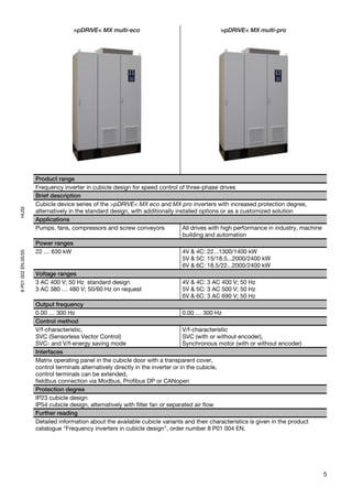
![>pDRIVE< MX multi-eco 400 V
General technical data
Mains voltage 380 V -15% up to 415 V +10%, 50 Hz for TT, TN or IT mains
Maximum current 120 % for 60 s per 10 minutes, 135 % for 2 seconds
Operating temperature 0...+40°C, up to +50°C with derating possible
Standards CE, RFI filter for 2nd “industrial environment” C3 integrated
General design Cubicle system Rittal TS8 in RAL 7035
controls in the cubicle door with additional protective cover,
cable entry from below, cubicle depth of 600 mm (622 mm incl. door handle)
Interfaces Control terminals directly on the inverter or alternatively in the cubicle, control
terminals can be extended, fieldbus connection via Modbus and CANopen or
optionally Profibus DP
Design
MX multi-eco 4V
IP23 Air flow through grid in cubicle door and mounted air guidance hood,
cubicle height of 2155 mm
IP54 Air flow through filter mats in cubicle door and a top mounted fan,
cubicle height of 2260 mm
IP54 with separated air Air flow through cubicle plinth and mounted air guidance hood, cooling of the
flow control part by means of filter fans in the cubicle door,
HUSI
cubicle height of 2355 mm (incl. 200 mm plinth)
Standard equipment Frequency inverter >pDRIVE< MX eco, main switch, mains fuses, AC or DC choke,
motor terminals, control panel and matrix operating panel in the door
Options Line contactor, AMF (output motor filter, partially with additional field), terminal
extensions, fieldbus, emergency stop button, safe standstill (control category 3
according to EN 954-1 / ISO 13849-1 for "Safe Standstill" (stop category 0 or 1)),
8 P01 002 EN.05/05
cubicle lighting, cubicle heating, and much more.
Motor output Output current Dimensions [mm]
Type
[kW] [A] Width Depth Height
>pDRIVE< MX multi-eco 4V
4V22-S 22 48 600 600
IP23:
4V30-S 30 66 600 600
2155 mm
4V37-S 37 79 600 600
4V45-S 45 94 600 600
IP54:
4V55-S 55 116 600 600 2260 mm
4V75-S 75 160 600 600
4V90-S 90 179 600 600
4V110-S 110 215 600 600
4V132-S 132 259 600 600
4V160-S 160 314 600 600 IP23:
4V200-S 200 387 600 600 2155 mm
4V250-S 250 481 800 600
4V315-S 315 616 800 600 IP54:
4V355-S 355 671 1000 (1400) 600 2260 (2355) mm
4V400-S 400 759 1000 (1400) 600
4V500-S 500 941 1000 (1400) 600
4V630-S 630 1188 1200 (1600) 600
( ) Values in brackets for IP54 with separated air flow
12](https://image.slidesharecdn.com/pdrivemxpro-121022142023-phpapp01/85/P-drive-m-xpro-14-320.jpg)

![Motor output Output current Dimensions [mm]
Type
P1 / P2 [kW] I1 / I2 [A] Width Depth Height
>pDRIVE< MX multi-pro 4V
4V22-S 22 48 600 600
4V30-S 30 66 600 600 IP23:
2155 mm
4V37-S 37 79 600 600
4V45-S 45 94 600 600
IP54:
4V55-S 55 116 600 600 2260 mm
4V75-S 75 160 600 600
4V90/110-S 90 / 110 179 / 215 600 600
4V110/132-S 110 / 132 215 / 259 600 600
4V132/160-S 132 / 160 259 / 314 600 600 IP23:
4V160/200-S 160 / 200 314 / 387 600 600 2155 mm
4V200/250-S 200 / 250 387 / 481 600 600
4V250/315-S 250 / 315 481 / 616 800 600 IP54:
4V315/400-S 315 / 400 616 / 759 1000 (1400) 600 2260 (2355) mm
4V400/500-S 400 / 500 759 / 941 1000 (1400) 600
4V500/630-S 500 / 630 941 / 1188 1200 (1600) 600
>pDRIVE< MX multi-pro 4C
4C500/630-S 500 / 630 920 / 1100 1800 600 2000
HUSI
4C630/710-S 630 / 710 1100 / 1230 1800 600 2000
4C710/900-S 710 / 900 1260 / 1580 3000 600 2000
4C900/1100-S 900 / 1100 1580 / 1860 3000 600 2000
4C1100/1300-S 1100 / 1300 1860 / 2200 3000 600 2000
4C1300/1400-S 1300 / 1400 2200 / 2430 3000 600 2000
8 P01 002 EN.05/05
( ) Values in brackets for IP54 with separated air flow
14](https://image.slidesharecdn.com/pdrivemxpro-121022142023-phpapp01/85/P-drive-m-xpro-16-320.jpg)

![Motor output Output current Dimensions [mm]
Type
P1 / P2 [kW] I1 / I2 [A] Width Depth Height
>pDRIVE< MX multi-pro 5V
5V15/18-S 15 / 18.5 24 / 29 600 (1000) 600
5V18/22-S 18.5 / 22 29 / 35 600 (1000) 600 IP23:
5V22/30-S 22 / 30 35 / 47 600 (1000) 600 2155 mm
5V30/37-S 30 / 37 47 / 59 600 (1000) 600
5V37/45-S 37 / 45 59 / 68 600 (1000) 600 IP54:
2260 mm
5V45/55-S 45 / 55 68 / 85 600 (1000) 600
5V55/75-S 55 / 75 85 / 110 600 (1000) 600
5V75/90-S 75 / 90 110 / 136 600 (1000) 600
5V90/110-S 90 / 110 136 / 165 600 (1000) 600
5V110/132-S 110 / 132 165 / 200 600 (1000) 600
5V132/160-S 132 / 160 200 / 240 600 (1000) 600 IP23:
2155 mm
5V160/200-S 160 / 200 240 / 312 800 (1200) 600
5V200/250-S 200 / 250 312 / 390 800 (1200) 600
IP54:
5V250/315-S 250 / 315 390 / 462 800 (1200) 600 2260 (2355) mm
5V315/400-S 315 / 400 462 / 590 1200 (1600) 600
5V400/500-S 400 / 500 590 / 740 1200 (1600) 600
5V500/630-S 500 / 630 740 / 900 1200 (1600) 600
HUSI
>pDRIVE< MX multi-pro 5C
5C500/630-S 500 / 630 740 / 920 1800 600 2000
5C630/800-S 630 / 800 920 / 1100 1800 600 2000
5C800/900-S 800 / 900 1100 / 1230 1800 600 2000
5C900/1100-S 900 / 1100 1260 / 1580 3000 600 2000
8 P01 002 EN.05/05
5C1100/1300-S 1100 / 1300 1580 / 1860 3000 600 2000
5C1300/1500-S 1300 / 1500 1860 / 2140 3000 600 2000
5C1500/1800-S 1500 / 1800 2020 / 2430 3000 600 2000
( ) Values in brackets for IP54 with separated air flow
16](https://image.slidesharecdn.com/pdrivemxpro-121022142023-phpapp01/85/P-drive-m-xpro-18-320.jpg)

![Motor output Output current Dimensions [mm]
Type
P1 / P2 [kW] I1 / I2 [A] Width Depth Height
>pDRIVE< MX multi-pro 6V
6V18/22-S 18 / 22 24 / 27 600 (1000) 600
6V22/30-S 22 / 30 27 / 35 600 (1000) 600 IP23:
6V30/37-S 30 / 37 35 / 43 600 (1000) 600 2155 mm
6V37/45-S 37 / 45 43 / 54 600 (1000) 600
6V45/55-S 45 / 55 54 / 62 600 (1000) 600 IP54:
2260 mm
6V55/75-S 55 / 75 62 / 84 600 (1000) 600
6V75/90-S 75 / 90 84 / 104 600 (1000) 600
6V90/110-S 90 / 110 104 / 125 600 (1000) 600
6V110/132-S 110 / 132 125 / 150 600 (1000) 600
6V132/160-S 132 / 160 150 / 180 600 (1000) 600
6V160/200-S 160 / 200 180 / 220 600 (1000) 600 IP23:
2155 mm
6V200/250-S 200 / 250 220 / 290 800 (1200) 600
6V250/315-S 250 / 315 290 / 355 800 (1200) 600
IP54:
6V315/400-S 315 / 400 355 / 420 800 (1200) 600 2260 (2355) mm
6V400/500-S 400 / 500 420 / 543 1200 (1600) 600
6V500/630-S 500 / 630 543 / 675 1200 (1600) 600
6V630/800-S 630 / 800 675 / 840 1200 (1600) 600
HUSI
>pDRIVE< MX multi-pro 6C
6C630/800-S 630 / 800 675 / 840 1800 600 2000
6C800/1000-S 800 / 1000 840 / 1050 1800 600 2000
6C1000/1200-S 1000 / 1200 1010 / 1230 1800 600 2000
6C1200/1500-S 1200 / 1500 1260 / 1580 3000 600 2000
8 P01 002 EN.05/05
6C1500/1800-S 1500 / 1800 1580 / 1860 3000 600 2000
6C1800/2100-S 1800 / 2100 1860 / 2140 3000 600 2000
6C2000/2400-S 2000 / 2400 2020 / 2430 3000 600 2000
( ) Values in brackets for IP54 with separated air flow
18](https://image.slidesharecdn.com/pdrivemxpro-121022142023-phpapp01/85/P-drive-m-xpro-20-320.jpg)


![>pDRIVE< MX eco 4V0,75 4V1,5 4V2,2 4V3,0 4V4,0
Nominal data
Motor rating
PN [kW] 0.75 1.5 2.2 3.0 4.0
−
≥100
PN [hp] 1 2 3 5
Continuous output power
SN 400 [kVA] VN = 400 V 1.6 2.8 4.0 5.4 7.3
SN 460 [kVA] VN = 460 V 1.8 3.3 4.6 6.2 8.4
Continuous output current
IN 400 [A] VN = 400 V 2.3 4.1 5.8 7.8 10.5 ≥10
IN 460 [A] VN = 460 V 2.3 4.1 5.8 7.8 10.5
Maximum current for 60 s per 10 minutes
IMAX [A] 2.8 4.9 7.0 9.4 12.6
≥100
Input current (without choke)
IIN 400 [A] VN = 400 V 3.7 5.8 8.2 10.7 14.1
IIN 460 [A] VN = 460 V 3.0 5.3 7.1 9 11.5
Characteristics For installation keep a minimum
Efficiency [%] > 94.5 > 95.5 > 96.0 > 96.0 > 96.5 distance of 50 mm between the
Losses [W] at IN 44 64 87 115 145 units and the side wall.
Weight approx. [kg] 3 3 3 4 4
Ambient conditions
Volume cooling air [m3/h] 17 17 17 55 55
Sound pressure [dB(A)] 43 43 55 55 55
HUSI
Mains short circuit c. [kA] 5 5 5 5 5
Dimensions
Dimension A1 [mm] 230 230 230 260 260
Dimension A2 [mm] 220 220 220 249 249
Dimension A3 [mm] 5 5 5 7 7
8 P01 002 EN.05/05
Dimension B1 [mm] 130 130 130 155 155
Dimension B2 [mm] 113.5 113.5 113.5 138 138 When you remove the IP41
Dimension C1 [mm] 152 152 152 164 164 protective cover the units can be
Dimension C2 [mm] 175 175 175 187 187 mounted without any distance
sideways.
Dimension C3 [mm] 174 174 174 186 186
See also chapter "Power
Dimension C4 [mm] 197 197 197 209 209
decrease", page 154.
Dimension C5 [mm] 196 196 196 208 208
Dimension C6 [mm] 219 219 219 231 231
Fixing D1 [mm] 4x ∅4.5 4x ∅4.5 4x ∅4.5 4x ∅4.5 4x ∅4.5
with 2 option cards with 1 option card Basic device without option card
MX eco 4V | 43](https://image.slidesharecdn.com/pdrivemxpro-121022142023-phpapp01/85/P-drive-m-xpro-45-320.jpg)
![>pDRIVE< MX eco 4V5,5 4V7,5 4V11 4V15 4V18
Nominal data
Motor rating
PN [kW] 5.5 7.5 11 15 18.5
≥100
PN [hp] 7.5 10 15 20 25
Continuous output power
SN 400 [kVA] VN = 400 V 9.9 12.2 19.2 23 28
SN 460 [kVA] VN = 460 V 11.4 14 22 26 33
Continuous output current
IN 400 [A] VN = 400 V 14.3 17.6 27.7 33 41 ≥10
IN 460 [A] VN = 460 V 14.3 17.6 27.7 33 41
Maximum current for 60 s per 10 minutes
IMAX [A] 17.2 21 33 40 49
≥100
Input current (without choke)
IIN 400 [A] VN = 400 V 20.3 27.0 36.6 48 46
IIN 460 [A] VN = 460 V 17.0 22.2 30.0 39 38
Characteristics For installation keep a minimum
Efficiency [%] > 96.5 > 97.0 > 97.0 > 97.0 > 97.0 distance of 50 mm between the
Losses [W] at IN 180 220 320 390 485 units and the side wall.
Weight approx. [kg] 5.5 5.5 7 9 9
Ambient conditions
Volume cooling air [m3/h] 110 110 160 250 250
Sound pressure [dB(A)] 56 56 57 60 60
HUSI
Mains short circuit c. [kA] 5 5 5 5 22
Dimensions
Dimension A1 [mm] 295 295 295 400 400
Dimension A2 [mm] 283 283 283 386 386
Dimension A3 [mm] 6 6 6 8 8
8 P01 002 EN.05/05
Dimension B1 [mm] 175 175 210 230 230
Dimension B2 [mm] 158 158 190 210 210 When you remove the IP41
Dimension C1 [mm] 164 164 190 190 190 protective cover the units can be
Dimension C2 [mm] 187 187 213 213 213 mounted without any distance
sideways.
Dimension C3 [mm] 186 186 212 212 212
See also chapter "Power
Dimension C4 [mm] 209 209 235 235 235
decrease", page 154.
Dimension C5 [mm] 208 208 234 234 234
Dimension C6 [mm] 231 231 257 257 257
Fixing D1 [mm] 4x ∅5.5 4x ∅5.5 4x ∅5.5 4x ∅5.5 4x ∅5.5
with 2 option cards with 1 option card Basic device without option card
44 | MX eco 4V](https://image.slidesharecdn.com/pdrivemxpro-121022142023-phpapp01/85/P-drive-m-xpro-46-320.jpg)
![>pDRIVE< MX eco 4V22 4V30 4V37
Nominal data
Motor rating
PN [kW] 22 30 37
PN [hp] 30 40 50
≥100
Continuous output power
SN 400 [kVA] VN = 400 V 33 46 55
SN 460 [kVA] VN = 460 V 38 53 63
Continuous output current
IN 400 [A] VN = 400 V 48 66 79
≥10
IN 460 [A] VN = 460 V 48 66 79
Maximum current for 60 s per 10 minutes
IMAX [A] 58 79 95
≥100
Input current (without choke)
IIN 400 [A] VN = 400 V 50 66 84
IIN 460 [A] VN = 460 V 42 56 69
Characteristics
For installation keep a minimum
Efficiency [%] > 97.0 > 97.0 > 97.0 distance of 50 mm between the
Losses [W] at IN 720 980 1180 units and the side wall.
Weight approx. [kg] 19 26 26
Ambient conditions
Volume cooling air [m3/h] 200 200 200
Sound pressure [dB(A)] 60 64 64
HUSI
Mains short circuit c. [kA] 22 22 22
Dimensions
Dimension A1 [mm] 420 550 550
Dimension A2 [mm] 403 529 529
Dimension A3 [mm] 8.5 11 11
8 P01 002 EN.05/05
Dimension B1 [mm] 240 240 240
Dimension B2 [mm] 206 206 206 When you remove the IP41
protective cover the units can be
Dimension C1 [mm] 213 243 243
mounted without any distance
Dimension C2 [mm] 236 266 266 sideways.
Dimension C3 [mm] 235 265 265 See also chapter "Power
Dimension C4 [mm] 258 288 288 decrease", page 154.
Dimension C5 [mm] 257 287 287
Dimension C6 [mm] 280 310 310
Fixing D1 [mm] 4 x ∅ 5.5 4 x ∅ 5.5 4 x ∅ 5.5
with 2 option cards with 1 option card Basic device without option card
MX eco 4V | 45](https://image.slidesharecdn.com/pdrivemxpro-121022142023-phpapp01/85/P-drive-m-xpro-47-320.jpg)
![>pDRIVE< MX eco 4V45 4V55 4V75
Nominal data
Motor rating
PN [kW] 45 55 75
≥100
PN [hp] 60 75 100
Continuous output power
SN 400 [kVA] VN = 400 V 65 80 111
SN 460 [kVA] VN = 460 V 75 92 128
Continuous output current
IN 400 [A] VN = 400 V 94 116 160 ≥10
IN 460 [A] VN = 460 V 94 116 160
Maximum current for 60 s per 10 minutes
IMAX [A] 113 139 192
≥100
Input current (without choke)
IIN 400 [A] VN = 400 V 104 120 167
IIN 460 [A] VN = 460 V 85 101 137
Characteristics For installation keep a minimum
Efficiency [%] > 97.0 > 97.0 > 97.0 distance of 50 mm between the
Losses [W] at IN 1360 1560 2320 units and the side wall.
Weight approx. [kg] 44 44 44
Ambient conditions
Volume cooling air [m3/h] 400 400 400
Sound pressure [dB(A)] 64 64 64
HUSI
Mains short circuit c. [kA] 22 22 22
Dimensions
Dimension A1 [mm] 630 630 630
Dimension A2 [mm] 604.5 604.5 604.5
Dimension A3 [mm] 15.5 15.5 15.5
8 P01 002 EN.05/05
Dimension B1 [mm] 320 320 320 When you remove the IP41
Dimension B2 [mm] 280 280 280 protective cover the units can be
Dimension C1 [mm] 290 290 290 mounted without any distance
Dimension C3 [mm] 290 290 290 sideways.
Dimension C4 [mm] 312 312 312 See also chapter "Power
Dimension C5 [mm] 311 311 311 decrease", page 154.
Dimension C6 [mm] 334 334 334
Fixing D1 [mm] 4x∅9 4x∅9 4x∅9
with 2 option cards with 1 option card Basic device without option card
46 | MX eco 4V](https://image.slidesharecdn.com/pdrivemxpro-121022142023-phpapp01/85/P-drive-m-xpro-48-320.jpg)
![>pDRIVE< MX eco 4V90 4V110 4V132 4V160
Nominal data
Motor rating
PN [kW] 90 110 132 160
PN [hp] 125 150 200 250
Continuous output power
SN 400 [kVA] VN = 400 V 124 149 179 218
SN 460 [kVA] VN = 460 V 143 171 206 250
Continuous output current
IN 400 [A] VN = 400 V 179 215 259 314
IN 460 [A] VN = 460 V 179 215 259 314
Maximum current for 60 s per 10 minutes
IMAX [A] 215 258 311 377
Input current (with option >pDRIVE< DCL-BOX)
IIN 400 [A] VN = 400 V 158 188 226 271
IIN 460 [A] VN = 460 V 143 168 224 275
Characteristics
Efficiency [%] > 97.5 > 97.5 > 97.5 > 97.6
Losses [W] at IN 2210 2810 3330 3710
Weight approx. [kg] 60 60 74 80 If the devices are installed without
Ambient conditions any free space sideways, higher
Volume cooling air [m3/h] 400 400 600 600 minimum distances are required
for sufficient cooling (values in
Sound pressure [dB(A)] 61 61 69 71
HUSI
1.)
brackets).
Mains short circuit c. [kA] 50 50 1.) 50 1.) 50 1.)
Dimensions
In either case avoid air short
Dimension A1 [mm] 680 680 782 950 circuits.
Dimension A2 [mm] 650 650 758 920
Dimension A3 [mm] 15 15 12 15
8 P01 002 EN.05/05
Dimension B1 [mm] 310 310 350 330
Dimension B2 [mm] 250 250 298 285
1.)
Dimension C1 [mm] 377 377 377 377 in combination with DC choke
Dimension C3 [mm] 377 377 377 377 option >pDRIVE< DCL-BOX
Dimension C4 [mm] 392 392 392 392
Fixing D1 [mm] 4x ∅11.5 4x ∅11.5 4x ∅11.5 4x ∅11.5
with 2 option cards Basic device without or with 1 option card
MX eco 4V | 47](https://image.slidesharecdn.com/pdrivemxpro-121022142023-phpapp01/85/P-drive-m-xpro-49-320.jpg)
![>pDRIVE< MX eco 4V200 4V250 4V315
Nominal data
Motor rating
PN [kW] 200 250 315
PN [hp] 300 400 500
Continuous output power
SN 400 [kVA] VN = 400 V 268 333 427
SN 460 [kVA] VN = 460 V 308 383 491
Continuous output current
IN 400 [A] VN = 400 V 387 481 616
IN 460 [A] VN = 460 V 387 481 616
Maximum current for 60 s per 10 minutes
IMAX [A] 464 577 739
Input current (with option >pDRIVE< DCL-BOX)
IIN 400 [A] VN = 400 V 338 418 527
IIN 460 [A] VN = 460 V 331 435 544
Characteristics
Efficiency [%] > 97.7 > 97.7 > 97.7
Losses [W] at IN 4450 5890 7250
Weight approx. [kg] 110 140 140 If the devices are installed without
Ambient conditions any free space sideways, higher
Volume cooling air [m3/h] 800 1200 1200 minimum distances are required
for sufficient cooling (values in
Sound pressure [dB(A)] 72 73 73
HUSI
1.)
brackets).
Mains short circuit c. [kA] 50 50 1.) 50 1.)
Dimensions
In either case avoid air short
Dimension A1 [mm] 950 950 950 circuits.
Dimension A2 [mm] 920 920 920
Dimension A3 [mm] 15 15 15
8 P01 002 EN.05/05
Dimension B1 [mm] 430 585 585
Dimension B2 [mm] 350 540 540
1.)
Dimension C1 [mm] 377 377 377 in combination with DC choke
Dimension C3 [mm] 377 377 377 option >pDRIVE< DCL-BOX
Dimension C4 [mm] 392 392 392
Fixing D1 [mm] 4x ∅11.5 4x ∅11.5 4x ∅11.5
with 2 option cards Basic device without or with 1 option card
48 | MX eco 4V](https://image.slidesharecdn.com/pdrivemxpro-121022142023-phpapp01/85/P-drive-m-xpro-50-320.jpg)
![>pDRIVE< MX eco 4V355 4V400 4V500 4V630
Nominal data
Motor rating
PN [kW] 355 400 500 630
PN [hp] 550 600 700 900
Continuous output power
SN 400 [kVA] VN = 400 V 465 526 652 823
SN 460 [kVA] VN = 460 V 535 605 750 947
Continuous output current
IN 400 [A] VN = 400 V 671 759 941 1188
IN 460 [A] VN = 460 V 671 759 941 1080
Maximum current for 60 s per 10 minutes
IMAX [A] 805 911 1129 1426
Input current (with option >pDRIVE< DCL-BOX)
IIN 400 [A] VN = 400 V 592 660 834 1037
IIN 460 [A] VN = 460 V 597 644 760 964
Characteristics
Efficiency [%] > 97.8 > 97.8 > 97.8 > 97.8
Losses [W] at IN 7660 8810 11150 13830
Weight approx. [kg] 215 215 225 300
Ambient conditions If the devices are installed without
any free space sideways, higher
Volume cooling air [m3/h] 1800 1800 1800 2400
minimum distances are required
Sound pressure [dB(A)] 75 75 75 75
HUSI
for sufficient cooling (values in
1.)
Mains short circuit c. [kA] 50 50 1.) 50 1.) 50 1.) brackets).
Dimensions
Dimension A1 [mm] 1150 1150 1150 1150 In either case avoid air short
Dimension A2 [mm] 1120 1120 1120 1120 circuits.
Dimension A3 [mm] 15 15 15 15
8 P01 002 EN.05/05
Dimension B1 [mm] 880 880 880 1110
Dimension B2 [mm] 417.5 417.5 417.5 532.5
1.)
Dimension C1 [mm] 377 377 377 377 in combination with DC choke
Dimension C3 [mm] 377 377 377 377 option >pDRIVE< DCL-BOX
Dimension C4 [mm] 392 392 392 392
Fixing D1 [mm] 5x ∅11.5 5x ∅11.5 5x ∅11.5 6x ∅11.5
2 option cards 0/1 option card MX eco 4V400...4V500 MX eco 4V630
MX eco 4V | 49](https://image.slidesharecdn.com/pdrivemxpro-121022142023-phpapp01/85/P-drive-m-xpro-51-320.jpg)


![Power decrease
Depending on the chosen pulse frequency and the maximum ambient temperature a power increase is
possible or a power reduction is necessary. This can be determined by means of the following diagrams.
>pDRIVE< MX eco 4V0,75...4V75 >pDRIVE< MX eco 4V90...4V630
I/I N
IP20 IP41
110
100
90 40°C 35°C
80 45°C 40°C
70 50°C 45°C
60 55°C 50°C
50 60°C 55°C
40
0 2 4 6 8 10 12 14 16
Pulse frequency [kHz]
IP20...upper protective cover removed
IP41...device with upper protective cover
HUSI
Please observe the following guidelines to guarantee trouble-free operation of the drive:
• At higher pulse frequencies the allowed motor cable length is reduced (see chapter "Motor cable
lengths", page 62).
• Select a motor which is at most one type bigger.
8 P01 002 EN.05/05
The installation of the DCL box and the terminal box does not have any effect on the cooling and from
there also the power increase or reduction of the frequency inverter is independent from the use of
these options.
If the heat sink temperature is too high, the pulse frequency is automatically reduced to prevent an
overload of the inverter.
54 | MX eco 4V](https://image.slidesharecdn.com/pdrivemxpro-121022142023-phpapp01/85/P-drive-m-xpro-56-320.jpg)


![Fuses and cable cross sections
The >pDRIVE< MX eco frequency inverters do not include any input fuses. They have to be provided externally
for the case that the electronic protective mechanism of the inverters fails. Thus they are a secondary
protection of the inverter to protect the power cables against overload and to protect the input rectifier in case
of an internal short-circuit.
The below-mentioned diameters for 3-wire cables are recommended values for laying the cable in air at max.
40°C ambient temperature, based on the regulations ÖVN EN 1 and VDE 0100.
The lines in the cubicles are dimensioned according to the specification for single conductors XLPE/EPR
copper 90°C.
The motor cables are dimensioned for the maximum continuous current. They apply to 0...100 Hz (up to
300 Hz the cable losses increase about 25 % because of the Skin-effect).
In case of other ambient conditions and different regulations the cable diameters must be adjusted.
Mains supply Frequency inverter Motor output
Pre- or Mains fuse Lines in the Max. Max.
Cu cable >pDRIVE< Motor cable
conduit "inverter cubicle mm2 cont. connec-
mm2 MX eco mm2 3.)
fuses 1.) protection" "sf (per phase) current tion
10 A 3 x 1.5 10 A (sf) 1.5 4V0,75 2.3 A 6 mm2 3 x 1.5
10 A 3 x 1.5 10 A (sf) 1.5 4V1,5 4.1 A 6 mm2 3 x 1.5
HUSI
10 [16] A 3 x 1.5 [2.5] 10 [16] A (sf) 1.5 [2.5] 4V2,2 5.8 A 6 mm2 3 x 1.5
16 [20] A 3 x 2.5 16 [20] A (sf) 2.5 4V3,0 7.8 A 6 mm2 3 x 1.5
20 [25] A 3 x 2.5 [4] 16 [25] A (sf) 2.5 [4] 4V4,0 10.5 A 6 mm2 3 x 1.5
25 [40] A 3 x 4 [6] 25 [40] A (sf) 4 [6] 4V5,5 14.3 A 6 mm2 3 x 2.5
32 [40] A 3 x 4 [6] 25 [40] A (sf) 4 [6] 4V7,5 17.6 A 6 mm2 3 x 2.5
16 mm2
8 P01 002 EN.05/05
40 [63] A 3 x 6 [16] 40 [63] A (sf) 6 [10] 4V11 27.7 A 3x4
63 [80] A 3 x 16 [25] 50 [80] A (sf) 10 [16] 4V15 33 A 35 mm2 3x6
63 [80] A 3 x 16 [25] 50 [80] A (sf) 10 [16] 4V18 41 A 35 mm2 3 x 10
63 [80] A 3 x 16 [25] 63 [80] A sf A 10 [16] 4V22 48 A 50 mm2 3 x 10
80 [100] A 3 x 25 [35] 80 [100] A sf A 16 [25] 4V30 66 A 50 mm2 3 x 16
100 [125] A 3 x 35 [50] 100 [125] A sf A 25 [35] 4V37 79 A 50 mm2 3 x 25
125 [160] A 3 x 50 [70] 125 [160] A sf B 35 [50] 4V45 94 A 120 mm2 3 x 35
160 [200] A 3 x 70 [95] 160 [200] A sf B 50 [70] 4V55 116 A 120 mm2 3 x 50
200 [250] A 3 x 95 [120] 200 [250] A sf B 70 [95] 4V75 160 A 120 mm2 3 x 70
250 A 3 x 120 250 A sf C 95 4V90 179 A M10 3 x 95
250 A 3 x 120 250 A sf C 95 4V110 215 A M10 3 x 120
315 A 3 x 185 315 A sf C 120 4V132 259 A M10 3 x 150
400 A 2 x (3 x 120) 400 A sf D 185 4V160 314 A M10 2 x (3 x 95)
500 A 2 x (3 x 150) 500 A sf D 2 x 120 4V200 387 A M12 2 x (3 x 120)
630 A 2 x (3 x 185) 630 A sf E 2 x 150 4V250 481 A M12 2 x (3 x 150)
800 A 3 x (3 x 185) 800 A sf F 3 x 150 4V315 616 A M12 3 x (3 x 150)
1000 A 4 x (3 x 185) 800 A sf F 3 x 150 4V355 671 A M12 3 x (3 x 150)
1000 A 4 x (3 x 185) 900 A sf F 3 x 185 4V400 759 A M12 3 x (3 x 185)
1250 A 4 x (3 x 240) 2 x 630 A sf 2.) E 2 x 2 x 150 4V500 941 A M12 4 x (3 x 185)
1600 A 6 x (3 x 240) 2 x 800 A sf 2.) F 2 x 3 x 150 4V630 1188 A M12 5 x (3 x 185)
1.)
Recommended pre-fuses suitable for DOL starting with bypass circuit.
2.)
2 x 3-pole fuses because of parallel supply
3.)
In case of bypass operation the motor cable has to be dimensioned according to the pre- or conduit fuses !
[ ] If the inverters are used without the option >pDRIVE< DCL, >pDRIVE< NDU or >pDRIVE< HF consider the
values in brackets.
MX eco 4V | 59](https://image.slidesharecdn.com/pdrivemxpro-121022142023-phpapp01/85/P-drive-m-xpro-61-320.jpg)


![>pDRIVE< MX pro 4V0,75 4V1,5 4V2,2 4V3,0 4V4,0
Nominal data
Motor rating
PN [kW] - Power 1 0.75 1.5 2.2 3.0 4.0
PN [hp] - Power 1 1 2 3 − 5
Continuous output power
≥100
SN 400 [kVA] VN = 400 V 1.6 2.8 4.0 5.4 7.3
SN 460 [kVA] VN = 460 V 1.8 3.3 4.6 6.2 8.4
Continuous output current
IN 400 [A] VN = 400 V 2.3 4.1 5.8 7.8 10.5
IN 460 [A] VN = 460 V 2.3 4.1 5.8 7.8 10.5
Maximum current for 60 s per 10 minutes ≥10
IMAX [A] - Power 1 3.5 6.2 8.7 11.7 15.8
Input current (without choke)
IIN 400 [A] VN = 400 V 3.7 5.8 8.2 10.7 14.1
≥100
IIN 460 [A] VN = 460 V 3.0 5.3 7.1 9 11.5
Braking unit
PCONT [kW] 0.75 1.5 2.2 3.0 4.0
PMAX for 60 s [kW] 1.1 2.3 3.3 4.5 6.0 For installation keep a minimum
RMIN / RMAX [Ω] 56/500 56/250 56/175 34/125 34/100 distance of 50 mm between the
Characteristics units and the side wall.
Efficiency [%] > 94.5 > 95.5 > 96.0 > 96.0 > 96.5
Losses [W] at IN 44 64 87 115 145
HUSI
Weight approx. [kg] 3 3 3 4 4
Ambient conditions
Volume cooling air [m3/h] 17 17 17 55 55
Sound pressure [dB(A)] 43 43 55 55 55
Mains short circuit c. [kA] 5 5 5 5 5
8 P01 002 EN.05/05
Dimensions
Dimension A1 [mm] 230 230 230 260 260
Dimension A2 [mm] 220 220 220 249 249
Dimension A3 [mm] 5 5 5 7 7 When you remove the IP41
Dimension B1 [mm] 130 130 130 155 155 protective cover the units can be
mounted without any distance
Dimension B2 [mm] 113.5 113.5 113.5 138 138
sideways.
Dimension C1 [mm] 152 152 152 164 164
See also chapter "Power
Dimension C2 [mm] 175 175 175 187 187 decrease", page 154.
Dimension C3 [mm] 174 174 174 186 186
Dimension C4 [mm] 197 197 197 209 209
Dimension C5 [mm] 196 196 196 208 208
Dimension C6 [mm] 219 219 219 231 231
Fixing D1 [mm] 4x ∅4.5 4x ∅4.5 4x ∅4.5 4x ∅4.5 4x ∅4.5
with 2 option cards with 1 option card Basic device without option card
84 | MX pro 4V](https://image.slidesharecdn.com/pdrivemxpro-121022142023-phpapp01/85/P-drive-m-xpro-86-320.jpg)
![>pDRIVE< MX pro 4V5,5 4V7,5 4V11 4V15 4V18
Nominal data
Motor rating
PN [kW] - Power 1 5.5 7.5 11 15 18.5
PN [hp] - Power 1 7.5 10 15 20 25
Continuous output power
SN 400 [kVA] VN = 400 V 9.9 12.2 19.2 23 28
≥100
SN 460 [kVA] VN = 460 V 11.4 14 22 26 33
Continuous output current
IN 400 [A] VN = 400 V 14.3 17.6 27.7 33 41
IN 460 [A] VN = 460 V 14.3 17.6 27.7 33 41
Maximum current for 60 s per 10 minutes ≥10
IMAX [A] - Power 1 21.5 26.4 42 50 62
Input current (without choke)
IIN 400 [A] VN = 400 V 20.3 27.0 36.6 48 46
≥100
IIN 460 [A] VN = 460 V 17.0 22.2 30.0 39 38
Braking unit
PCONT [kW] 5.5 7.5 11 15 18.5
PMAX for 60 s [kW] 8.3 11 17 23 28 For installation keep a minimum
RMIN / RMAX [Ω] 25/75 20/55 15/38 14/28 14/24 distance of 50 mm between the
Characteristics units and the side wall.
Efficiency [%] > 96.5 > 97.0 > 97.0 > 97.0 > 97.0
Losses [W] at IN 180 220 320 390 485
HUSI
Weight approx. [kg] 5.5 5.5 7 9 9
Ambient conditions
Volume cooling air [m3/h] 110 110 160 250 250
Sound pressure [dB(A)] 56 56 57 60 60
Mains short circuit c. [kA] 5 5 5 5 22
8 P01 002 EN.05/05
Dimensions
Dimension A1 [mm] 295 295 295 400 400
Dimension A2 [mm] 283 283 283 386 386
Dimension A3 [mm] 6 6 6 8 8 When you remove the IP41
Dimension B1 [mm] 175 175 210 230 230 protective cover the units can be
Dimension B2 [mm] 158 158 190 210 210 mounted without any distance
sideways.
Dimension C1 [mm] 164 164 190 190 190
See also chapter "Power
Dimension C2 [mm] 187 187 213 213 213 decrease", page 154.
Dimension C3 [mm] 186 186 212 212 212
Dimension C4 [mm] 209 209 235 235 235
Dimension C5 [mm] 208 208 234 234 234
Dimension C6 [mm] 231 231 257 257 257
Fixing D1 [mm] 4x ∅5.5 4x ∅5.5 4x ∅5.5 4x ∅5.5 4x ∅5.5
with 2 option cards with 1 option card Basic device without option card
MX pro 4V | 85](https://image.slidesharecdn.com/pdrivemxpro-121022142023-phpapp01/85/P-drive-m-xpro-87-320.jpg)
![>pDRIVE< MX pro 4V22 4V30 4V37
Nominal data
Motor rating
PN [kW] - Power 1 22 30 37
PN [hp] - Power 1 30 40 50
Continuous output power
SN 400 [kVA] VN = 400 V 33 46 55
≥100
SN 460 [kVA] VN = 460 V 38 53 63
Continuous output current
IN 400 [A] VN = 400 V 48 66 79
IN 460 [A] VN = 460 V 48 66 79
Maximum current for 60 s per 10 minutes
≥10
IMAX [A] - Power 1 72 99 119
Input current (without choke)
IIN 400 [A] VN = 400 V 50 66 84
≥100
IIN 460 [A] VN = 460 V 42 56 69
Braking unit
PCONT [kW] 22 30 37
PMAX for 60 s [kW] 33 45 56
For installation keep a minimum
RMIN / RMAX [Ω] 14/20 10/15 7/12
distance of 50 mm between the
Characteristics units and the side wall.
Efficiency [%] > 97.0 > 97.0 > 97.0
Losses [W] at IN 720 980 1180
HUSI
Weight approx. [kg] 19 26 26
Ambient conditions
Volume cooling air [m3/h] 200 200 200
Sound pressure [dB(A)] 60 64 64
Mains short circuit c. [kA] 22 22 22
8 P01 002 EN.05/05
Dimensions
Dimension A1 [mm] 420 550 550
Dimension A2 [mm] 403 529 529
Dimension A3 [mm] 8.5 11 11 When you remove the IP41
protective cover the units can be
Dimension B1 [mm] 240 240 240
mounted without any distance
Dimension B2 [mm] 206 206 206 sideways.
Dimension C1 [mm] 213 243 243 See also chapter "Power
Dimension C2 [mm] 236 266 266 decrease", page 154.
Dimension C3 [mm] 235 265 265
Dimension C4 [mm] 258 288 288
Dimension C5 [mm] 257 287 287
Dimension C6 [mm] 280 310 310
Fixing D1 [mm] 4 x ∅ 5.5 4 x ∅ 5.5 4 x ∅ 5.5
with 2 option cards with 1 option card Basic device without option card
86 | MX pro 4V](https://image.slidesharecdn.com/pdrivemxpro-121022142023-phpapp01/85/P-drive-m-xpro-88-320.jpg)
![>pDRIVE< MX pro 4V45 4V55 4V75
Nominal data
Motor rating
PN [kW] - Power 1 45 55 75
PN [hp] - Power 1 60 75 100
Continuous output power
≥100
SN 400 [kVA] VN = 400 V 65 80 111
SN 460 [kVA] VN = 460 V 75 92 128
Continuous output current
IN 400 [A] VN = 400 V 94 116 160
IN 460 [A] VN = 460 V 94 116 160
Maximum current for 60 s per 10 minutes ≥10
IMAX [A] - Power 1 141 174 240
Input current (without choke)
IIN 400 [A] VN = 400 V 104 120 167
≥100
IIN 460 [A] VN = 460 V 85 101 137
Braking unit
PCONT [kW] 45 55 75
PMAX for 60 s [kW] 68 83 113 For installation keep a minimum
RMIN / RMAX [Ω] 5/10 4/8 3.3/6 distance of 50 mm between the
Characteristics units and the side wall.
Efficiency [%] > 97.0 > 97.0 > 97.0
Losses [W] at IN 1360 1560 2320
HUSI
Weight approx. [kg] 44 44 44
Ambient conditions
Volume cooling air [m3/h] 400 400 400
Sound pressure [dB(A)] 64 64 64
Mains short circuit c. [kA] 22 22 22
Dimensions
8 P01 002 EN.05/05
Dimension A1 [mm] 630 630 630
Dimension A2 [mm] 604.5 604.5 604.5
When you remove the IP41
Dimension A3 [mm] 15.5 15.5 15.5 protective cover the units can be
Dimension B1 [mm] 320 320 320 mounted without any distance
Dimension B2 [mm] 280 280 280 sideways.
Dimension C1 [mm] 290 290 290 See also chapter "Power
Dimension C3 [mm] 290 290 290 decrease", page 154.
Dimension C4 [mm] 312 312 312
Dimension C5 [mm] 311 311 311
Dimension C6 [mm] 334 334 334
Fixing D1 [mm] 4x∅9 4x∅9 4x∅9
with 2 option cards with 1 option card Basic device without option card
Pos: 397 /Gliederungshilfen/---------------------- Abstand einfach ---------------------- @ 18mod_1201013206823_0.doc @ 77291
MX pro 4V | 87](https://image.slidesharecdn.com/pdrivemxpro-121022142023-phpapp01/85/P-drive-m-xpro-89-320.jpg)
![Pos: 398 /Technische Daten/PRO - Technische Daten 4V90/110...500/630 @ 18mod_1199949932544_132.doc @ 77069
>pDRIVE< MX pro 4V90/110 4V110/132 4V132/160
Nominal data
Motor rating
PN [kW] - Power 1/2 90/110 110/132 132/160
PN [hp] - Power 1/2 125/150 150/200 200/250
Continuous output power
SN 400 [kVA] VN = 400 V 124/149 149/179 179/218
SN 460 [kVA] VN = 460 V 143/171 171/206 206/250
Continuous output current
IN 400 [A] VN = 400 V 179/215 215/259 259/314
IN 460 [A] VN = 460 V 179/215 215/259 259/314
Maximum current for 60 s per 10 minutes
IMAX [A] - Power 1/2 269 / 258 323 / 311 389 / 377
Input current (with option >pDRIVE< DCL-BOX)
IIN 400 [A] VN = 400 V 159/188 194/226 229/271
IIN 460 [A] VN = 460 V 143/168 173/224 225/275
Braking unit
PCONT [kW] 70 85 100
PMAX for 10 s [kW] 135 165 200
RMIN / RMAX [Ω] 2.5/5.0 2.1/4.0 1.75/3.5
Characteristics
Efficiency [%] > 97.5 > 97.5 > 97.6
Losses [W] at IN 2210/2810 2520/3330 2950/3710 If the devices are installed without
HUSI
Weight approx. [kg] 60 74 80 any free space sideways, higher
Ambient conditions minimum distances are required
Volume cooling air [m3/h] 400 600 600 for sufficient cooling (values in
brackets).
Sound pressure [dB(A)] 61 69 71
Mains short circuit c. [kA] 50 1.) 50 1.) 50 1.)
8 P01 002 EN.05/05
In either case avoid air short
Dimensions
circuits.
Dimension A1 [mm] 680 782 950
Dimension A2 [mm] 650 758 920
Dimension A3 [mm] 15 12 15
1.)
Dimension B1 [mm] 310 350 330 in combination with DC choke
Dimension B2 [mm] 250 298 285 option >pDRIVE< DCL-BOX
Dimension C1 [mm] 377 377 377
Dimension C3 [mm] 377 377 377
Dimension C4 [mm] 392 392 392
Fixing D1 [mm] 4x ∅11.5 4x ∅11.5 4x ∅11.5
with 2 option cards Basic device without or with 1 option card
88 | MX pro 4V](https://image.slidesharecdn.com/pdrivemxpro-121022142023-phpapp01/85/P-drive-m-xpro-90-320.jpg)
![>pDRIVE< MX pro 4V160/200 4V200/250 4V250/315
Nominal data
Motor rating
PN [kW] - Power 1/2 160/200 200/250 250/315
PN [hp] - Power 1/2 250/300 300/400 400/500
Continuous output power
SN 400 [kVA] VN = 400 V 218/268 268/333 333/427
SN 460 [kVA] VN = 460 V 250/308 308/383 383/491
Continuous output current
IN 400 [A] VN = 400 V 314/387 387/481 481/616
IN 460 [A] VN = 460 V 314/387 387/481 481/616
Maximum current for 60 s per 10 minutes
IMAX [A] - Power 1/2 471 / 464 581 / 577 722 / 739
Input current (with option >pDRIVE< DCL-BOX)
IIN 400 [A] VN = 400 V 277/338 340/418 424/527
IIN 460 [A] VN = 460 V 281/331 333/435 442/544
Braking unit
PCONT [kW] 120 200 2.) 200 2.)
PMAX for 10 s [kW] 240 300 375
RMIN / RMAX [Ω] 1.75/2.75 1.05/2.2 1.05/1.75
Characteristics
Efficiency [%] > 97.7 > 97.7 > 97.7 If the devices are installed without
Losses [W] at IN 3490/4450 4560/5890 5430/7250 any free space sideways, higher
HUSI
Weight approx. [kg] 110 140 140 minimum distances are required
for sufficient cooling (values in
Ambient conditions
brackets).
Volume cooling air [m3/h] 800 1200 1200
Sound pressure [dB(A)] 72 73 73
1.) In either case avoid air short
Mains short circuit c. [kA] 50 50 1.) 50 1.)
circuits.
8 P01 002 EN.05/05
Dimensions
Dimension A1 [mm] 950 950 950
Dimension A2 [mm] 920 920 920
Dimension A3 [mm] 15 15 15
1.)
Dimension B1 [mm] 430 585 585 in combination with DC choke
Dimension B2 [mm] 350 540 540 option >pDRIVE< DCL-BOX
2.)
Dimension C1 [mm] 377 377 377 external braking unit
Dimension C3 [mm] 377 377 377
Dimension C4 [mm] 392 392 392
Fixing D1 [mm] 4x ∅11.5 4x ∅11.5 4x ∅11.5
with 2 option cards Basic device without or with 1 option card
MX pro 4V | 89](https://image.slidesharecdn.com/pdrivemxpro-121022142023-phpapp01/85/P-drive-m-xpro-91-320.jpg)
![>pDRIVE< MX pro 4V315/400 4V400/500 4V500/630
Nominal data
Motor rating
PN [kW] - Power 1/2 315/400 400/500 500/630
PN [hp] - Power 1/2 500/600 600/700 700/900
Continuous output power
SN 400 [kVA] VN = 400 V 427/526 526/652 652/823
SN 460 [kVA] VN = 460 V 491/605 605/750 750/861
Continuous output current
IN 400 [A] VN = 400 V 616/759 759/941 941/1188
IN 460 [A] VN = 460 V 616/759 759/941 941/1080
Maximum current for 60 s per 10 minutes
IMAX [A] - Power 1/2 924 / 911 1139 / 1129 1412 / 1426
Input current (with option >pDRIVE< DCL-BOX)
IIN 400 [A] VN = 400 V 529/660 675/834 834/1037
IIN 460 [A] VN = 460 V 547/644 660/760 761/964
Braking unit
PCONT [kW] 400 2.) 400 2.) 400 2.)
PMAX for 10 s [kW] 475 600 750
RMIN / RMAX [Ω] 0.7/1.4 0.7/1.1 0.7/0.85
Characteristics
Efficiency [%] > 97.8 > 97.8 > 97.8 If the devices are installed without
any free space sideways, higher
Losses [W] at IN 6880/8810 8630/11150 10530/13830
HUSI
minimum distances are required
Weight approx. [kg] 215 225 300 for sufficient cooling (values in
Ambient conditions brackets).
Volume cooling air [m3/h] 1800 1800 2400
Sound pressure [dB(A)] 75 75 75
In either case avoid air short
1.)
Mains short circuit c. [kA] 50 50 1.) 50 1.) circuits.
8 P01 002 EN.05/05
Dimensions
Dimension A1 [mm] 1150 1150 1150
Dimension A2 [mm] 1120 1120 1120
Dimension A3 [mm] 15 15 15 1.)
in combination with DC choke
Dimension B1 [mm] 880 880 1110
option >pDRIVE< DCL-BOX
Dimension B2 [mm] 417.5 417.5 532.5 2.)
Dimension C1 [mm] 377 377 377 external braking unit
Dimension C3 [mm] 377 377 377
Dimension C4 [mm] 392 392 392
Fixing D1 [mm] 5x ∅11.5 5x ∅11.5 6x ∅11.5
2 option cards 0/1 option card MX pro 4V315/400...4V400/500 MX pro 4V500/630
90 | MX pro 4V](https://image.slidesharecdn.com/pdrivemxpro-121022142023-phpapp01/85/P-drive-m-xpro-92-320.jpg)


![Power decrease
Depending on the chosen pulse frequency and the maximum ambient temperature a power increase is
possible or a power reduction is necessary. This can be determined by means of the following diagrams.
>pDRIVE< MX pro 4V0,75...4V75 >pDRIVE< MX pro 4V90/100...4V500/630
I/I N
IP20 IP41
110
100
90 40°C 35°C
80 45°C 40°C
70 50°C 45°C
60 55°C 50°C
50 60°C 55°C
40
0 2 4 6 8 10 12 14 16
Pulse frequency [kHz]
IP20...Top protective cover removed Power 1...Dimensioned for high overload
IP41...Device with top protective cover Power 2...Increased output power
HUSI
Please observe the following guidelines to guarantee trouble-free operation of the drive:
• At higher pulse frequencies the allowed motor cable length is reduced (see chapter "Motor cable
lengths", page 118 ).
• Select a motor which is at most one type bigger.
8 P01 002 EN.05/05
The installation of the DCL box and the terminal box does not have any effect on the cooling and from
there also the power increase or reduction of the frequency inverter is independent from the use of
these options.
If the heat sink temperature is too high, the pulse frequency is automatically reduced to prevent an
overload of the inverter.
MX pro 4V | 95](https://image.slidesharecdn.com/pdrivemxpro-121022142023-phpapp01/85/P-drive-m-xpro-97-320.jpg)


![Fuses and cable cross sections
The >pDRIVE< MX pro frequency inverters do not include any input fuses. They have to be provided externally
for the case that the electronic protective mechanism of the inverters fails. Thus they are a secondary
protection of the inverter to protect the power cables against overload and to protect the input rectifier in case
of an internal short-circuit.
The below-mentioned diameters for 3-wire cables are recommended values for laying the cable in air at max.
40°C ambient temperature, based on the regulations ÖVN EN 1 and VDE 0100.
The lines in the cubicles are dimensioned according to the specification for single conductors XLPE/EPR
copper 90°C.
The motor cables are dimensioned for the maximum continuous current. They apply to 0...100 Hz (up to
300 Hz the cable losses increase about 25 % because of the Skin-effect).
In case of other ambient conditions and different regulations the cable diameters must be adjusted.
Mains supply Frequency inverter Motor output
Pre- or Mains fuse Lines in the Max. Max.
Cu cable >pDRIVE< Motor cable
conduit "inverter cubicle mm2 cont. connec-
mm2 MX pro mm2 3.)
fuses 1.) protection" "sf" (per phase) current tion
10 A 3 x 1.5 10 A (sf) 1.5 4V0,75 2.3 A 6 mm2 3 x 1.5
10 A 3 x 1.5 10 A (sf) 1.5 4V1,5 4.1 A 6 mm2 3 x 1.5
HUSI
10 [16] A 3 x 1.5 [2.5] 10 [16] A (sf) 1.5 [2.5] 4V2,2 5.8 A 6 mm2 3 x 1.5
16 [20] A 3 x 2.5 16 [20] A (sf) 2.5 4V3,0 7.8 A 6 mm2 3 x 1.5
20 [25] A 3 x 2.5 [4] 16 [25] A (sf) 2.5 [4] 4V4,0 10.5 A 6 mm2 3 x 1.5
25 [40] A 3 x 4 [6] 25 [40] A (sf) 4 [6] 4V5,5 14.3 A 6 mm2 3 x 2.5
32 [40] A 3 x 4 [6] 25 [40] A (sf) 4 [6] 4V7,5 17.6 A 6 mm2 3 x 2.5
16 mm2
8 P01 002 EN.05/05
40 [63] A 3 x 6 [16] 40 [63] A (sf) 6 [10] 4V11 27.7 A 3x4
63 [80] A 3 x 16 [25] 50 [80] A (sf) 10 [16] 4V15 33 A 35 mm2 3x6
63 [80] A 3 x 16 [25] 50 [80] A (sf) 10 [16] 4V18 41 A 35 mm2 3 x 10
63 [80] A 3 x 16 [25] 63 [80] A sf A 10 [16] 4V22 48 A 50 mm2 3 x 10
80 [100] A 3 x 25 [35] 80 [100] A sf A 16 [25] 4V30 66 A 50 mm2 3 x 16
100 [125] A 3 x 35 [50] 100 [125] A sf A 25 [35] 4V37 79 A 50 mm2 3 x 25
125 [160] A 3 x 50 [70] 125 [160] A sf B 35 [50] 4V45 94 A 120 mm2 3 x 35
160 [200] A 3 x 70 [95] 160 [200] A sf B 50 [70] 4V55 116 A 120 mm2 3 x 50
200 [250] A 3 x 95 [120] 200 [250] A sf B 70 [95] 4V75 160 A 120 mm2 3 x 70
Power 1 – high overload
250 A 3 x 120 250 A sf C 95 4V90/110 179 A M10 3 x 95
315 A 3 x 185 315 A sf C 120 4V110/132 215 A M10 3 x 120
400 A 2 x (3 x 120) 350 A sf D 150 4V132/160 259 A M10 3 x 150
400 A 2 x (3 x 120) 400 A sf D 185 4V160/200 314 A M12 2 x (3 x 95)
500 A 2 x (3 x 150) 500 A sf E 2 x 120 4V200/250 387 A M12 2 x (3 x 120)
630 A 2 x (3 x 185) 630 A sf F 2 x 150 4V250/315 481 A M12 2 x (3 x 150)
800 A 3 x (3 x 185) 800 A sf F 3 x 150 4V315/400 616 A M12 3 x (3 x 150)
1000 A 4 x (3 x 185) 2 x 500 A sf 2.) E 2 x 2 x 120 4V400/500 759 A M12 3 x (3 x 185)
1250 A 4 x (3 x 240) 2 x 630 A sf 2.) F 2 x 2 x 150 4V500/630 941 A M12 4 x (3 x 185)
104 | MX pro 4V](https://image.slidesharecdn.com/pdrivemxpro-121022142023-phpapp01/85/P-drive-m-xpro-106-320.jpg)
![Mains supply Frequency inverter Motor output
Pre- or Mains fuse Lines in the Max. Max.
Cu cable >pDRIVE< Motor cable
conduit 2 "inverter cubicle mm2 cont. connec-
mm MX pro mm2 3.)
fuses 1.) protection" "sf" (per phase) current tion
Power 2 – high continuous load
250 A 3 x 120 250 A sf C 95 4V90/110 215 A M10 3 x 120
315 A 3 x 185 315 A sf C 120 4V110/132 259 A M10 3 x 150
400 A 2 x (3 x 120) 400 A sf D 185 4V132/160 314 A M10 2 x (3 x 95)
500 A 2 x (3 x 150) 500 A sf D 2 x 120 4V160/200 387 A M12 2 x (3 x 120)
630 A 2 x (3 x 185) 630 A sf E 2 x 150 4V200/250 481 A M12 2 x (3 x 150)
800 A 3 x (3 x 185) 800 A sf F 3 x 150 4V250/315 616 A M12 3 x (3 x 150)
1000 A 4 x (3 x 185) 900 A sf F 3 x 185 4V315/400 759 A M12 3 x (3 x 185)
1250 A 4 x (3 x 240) 2 x 630 A sf 2.) E 2 x 2 x 150 4V400/500 941 A M12 4 x (3 x 185)
1600 A 6 x (3 x 240) 2 x 800 A sf 2.) F 2 x 3 x 150 4V500/630 1188 A M12 5 x (3 x 185)
1.)
Recommended pre-fuses suitable for DOL starting with bypass circuit.
2.)
2 x 3-pole fuses because of parallel supply
3.)
In case of bypass operation the motor cable has to be dimensioned according to the pre- or conduit fuses !
[ ] If the inverters are used without the option >pDRIVE< DCL, >pDRIVE< NDU or >pDRIVE< HF consider the
values in brackets.
It is recommended to use super fast (semiconductor) fuses. Standard fast fuses or circuit breakers can also be
used but the rectifier could be damaged in case of an internal fault.
To protect the rectifier in case of a short-circuit the used fuses should not exceed the following I2t values
HUSI
(referring to 10 ms):
A B C D E F
3 2 3 2 3 2 3 2 2
5.10 A s 50.10 A s 160.10 A s 320.10 A s 780.10³ A s 1000.103 A2s
8 P01 002 EN.05/05
If the mains fuses blow the inverter already has a primary defect. Therefore, exchanging the blown
fuses and switching the inverter on again is not effective. Consequently, the use of circuit breakers is
not advantageous and has additionally the disadvantage of a slower switch-off.
A low cost alternative to screened motor cables is the use of NYCY or NYCWY cables (power cables
with concentric protective conductor).
MX pro 4V | 105](https://image.slidesharecdn.com/pdrivemxpro-121022142023-phpapp01/85/P-drive-m-xpro-107-320.jpg)


![Calculation of the braking power
1. Braking of the centrifugal mass with constant delay
TB =
∑ I ⋅ (n1 − n 2 ) TB ... Braking torque of the motor [Nm]
9.55 ⋅ t B Sum of the moments of inertia related to the
ΣI ...
motor shaft [kgm2]
n1 ... Speed before braking [rpm]
P = T ⋅ϖ 2π ⋅ n n2 ... Speed after braking [rpm]
ω=
60 tB ... Braking time [t]
Calculation of the moment of inertia
HUSI
2. Braking of transversal movements (e.g. long-travels) with constant delay
m ⋅ v2 Wkin ... Kinetic energy [Joule]
W =
kin
2 m ... Weight [kg]
Wkin
v ... Speed [m/s]
8 P01 002 EN.05/05
PB =
tB tB ... Braking time [s]
∧
∧ PB ... Peak braking power [W]
PB = PB ⋅ 2
PB ... Average over braking power during tB [W]
3. Braking of active, driving of loads (e.g. test bench)
TB ⋅ n PB ... Average over braking power during tB [W]
PB =
9.55 TB ... Braking torque [Nm]
n ... Braking speed [rpm]
4. Braking of hoistings during lowering
PB ... Average over braking power during tB [W]
PB = m ⋅ g ⋅ v
∧
PB ... Peak braking power [W]
∧ I ⋅ ω2
PB = m ⋅ (g + a ) ⋅ v + m ... Weight [kg]
tB
g ... Acceleration of gravity 9.81 m/s2
2π ⋅ n a ... Braking delay [m/s2]
ω=
60
v ... Lowering speed [m/s]
I ... Moment of inertia [kgm2]
ω ... Angular velocity [rad/s]
tB ... Braking time [s]
n ... Motor speed during lowering operation [rpm]
MX pro 4V | 113](https://image.slidesharecdn.com/pdrivemxpro-121022142023-phpapp01/85/P-drive-m-xpro-115-320.jpg)
![All previously calculated braking powers apply only under the assumption that there are no system losses (i.e.
η=1) or motor load torques.
Since both parts reduce the arising braking power, they must be observed precisely:
1. System losses
The losses occurring during motor operation must not only be applied during the braking procedure (generator
operation, quadrants II and IV), they also actively help during the braking procedure. Thus the efficiency is to
be included squared in the calculation of the braking power.
2. Load torques
Any existing load torques (as they are not taken into consideration in the overall efficiency), such as friction,
wind force, quadratic load torque of fans, air resistance, and so on, reduce the braking power. The load
torques or power is to be subtracted during the calculation of the braking power.
The braking power that is actually required can thus be calculated as follows:
∧
∧ ⎛∧ ⎞ PBReal ... Actual peak braking power [W]
PBReal = ⎜ P− PLoad ⎟ ⋅ ηtotal
⎜ ⎟
⎝ ⎠
PBReal ... Actual continuous braking power [W]
(
PBReal= P − P )
Load ⋅ ηtotal
ηtotal ... Total efficiency
PLoad ... Braking power of the load shares [W]
ηtotal = ηmech⋅ ηmot ⋅ 0.98
HUSI
Selection of the braking option
∧
The necessary braking option is primarily selected according to the necessary braking power ( Pb , Pb ), but also
the following aspects may play a role in the selection of the braking option:
8 P01 002 EN.05/05
− Mounting type and protection degree of the braking resistors
− Amount of wiring
− Problems with the accumulating thermal energy (air conditioning)
− Price and possibility for amortisation due to reduced energy costs
In case of operating with braking unit, the braking resistor is selected under consideration of the required
powers by means of the braking time/cycle diagram and the selection tables in these instructions.
In general, the following applies:
2 ∧
∧ Vd ... Maximum braking power [W]
Pmax = Pmax
R
PCont. ... Thermal continuous braking power [W]
2
PCont. = I ⋅ R Vd ... Braking unit activation level [V]
I ... Thermal continuous current limit of the braking
resistor (see set value TH) [A]
R ... Resistance value of the braking resistor [Ω]
See the characteristic curve in the cycle
PCycle ...
diagram.
The >pDRIVE< MX pro frequency inverters have parameters to monitor the braking power. If the
braking resistor does not match the overload characteristic to be used or the local regulations require
an additional protective device, a thermal relay must be integrated into the mains disconnection
mechanism.
114 | MX pro 4V](https://image.slidesharecdn.com/pdrivemxpro-121022142023-phpapp01/85/P-drive-m-xpro-116-320.jpg)


![>pDRIVE< MX pro 6V2,2/3,0 6V3,0/4,0 6V4,0/5,5
Nominal data
Motor rating (P1/P2)
PN [kW] VN = 500 V 1.5/2.2 2.2/3.0 3.0/4.0
≥100
PN [hp] VN = 600 V 2/3 3/(4) (4)/5
PN [kW] VN = 690 V 2.2/3.0 3.0/4.0 4.0/5.5
Continuous output power (P1/P2)
SN 500 [kVA] VN = 500 V 2.8/3.9 3.9/5 5/6.5
SN 600 [kVA] VN = 600 V 4.2/4.7 4.7/5.7 5.7/7.8
SN 690 [kVA] VN = 690 V 4.8/5.4 5.4/6.6 6.6/9 ≥10
Continuous output current (P1/P2)
IN 500 [A] VN = 500 V 3.2/4.5 4.5/5.8 5.8/7.5
IN 600 [A] VN = 600 V 4.0/4.5 4.5/5.5 5.5/7.5
≥100
IN 690 [A] VN = 690 V 4.0/4.5 4.5/5.5 5.5/7.5
Maximum current (P1/P2) for 60 s per 10 minutes
IMAX [A] VN = 500 V 4.8/5.4 6.8/7 8.7/9
IMAX [A] VN = 600 V 6/5.4 6.8/6.6 8.3/9 For installation keep a minimum
IMAX [A] VN = 690 V 6/5.4 6.8/6.6 8.3/9 distance of 50 mm between the units
side and the wall.
Input current (without external choke)
IIN 500 [A] VN = 500 V 3.8/5.2 5.2/6.8 6.8/8.6
IIN 600 [A] VN = 600 V 3.2/4.4 4.4/5.7 5.7/7.2
IIN 690 [A] VN = 690 V 4.0/5.2 5.2/6.6 6.6/8.6
Braking unit
HUSI
PCONT [kW] 2.2 3.0 4.0
PMAX for 60 s [kW] 3.3 4.5 6
RMIN / RMAX [Ω] 80/350 80/260 80/200
Characteristics
Efficiency [%] > 97 > 97 > 97
8 P01 002 EN.05/05
Losses [W] at IN 115/120 120/140 140/160
Weight approx. [kg] 20 20 20 If you remove the IP41 protective
Ambient conditions cover the units can be installed
without any distance sideways.
Volume cooling air [m3/h] 200 200 200
Sound pressure [dB(A)] 60 60 60
Mains short circuit [kA] 22 22 22
with 2 option cards with 1 option card Basic device without option card
142 | MX pro 6V](https://image.slidesharecdn.com/pdrivemxpro-121022142023-phpapp01/85/P-drive-m-xpro-144-320.jpg)
![>pDRIVE< MX pro 6V5,5/7,5 6V7,5/11 6V11/15
Nominal data
Motor rating (P1/P2)
PN [kW] VN = 500 V 4.0/5.5 5.5/7.5 7.5/11
≥100
PN [hp] VN = 600 V 5/7.5 7.5/10 10/15
PN [kW] VN = 690 V 5.5/7.5 7.5/11 11/15
Continuous output power (P1/P2)
SN 500 [kVA] VN = 500 V 6.5/8.7 8.7/11.3 11.7/15.6
SN 600 [kVA] VN = 600 V 7.8/10.4 10.4/14.0 14.0/19.2
SN 690 [kVA] VN = 690 V 9/12 12/16 16/22 ≥10
Continuous output current (P1/P2)
IN 500 [A] VN = 500 V 7.5/10 10/13.5 13.5/18.5
≥100
IN 600 [A] VN = 600 V 7.5/10 10/13.5 13.5/18.5
IN 690 [A] VN = 690 V 7.5/10 10/13.5 13.5/18.5
Maximum current (P1/P2) for 60 s per 10 minutes
IMAX [A] VN = 500 V 11.3/12 15/16 20/22
IMAX [A] VN = 600 V 11.3/12 15/16 20/22 For installation keep a minimum
IMAX [A] VN = 690 V 11.3/12 15/16 20/22 distance of 50 mm between the units
side and the wall.
Input current (without external choke)
IIN 500 [A] VN = 500 V 8.6/11 11/15 15/20
IIN 600 [A] VN = 600 V 7.2/10 10/13 13/17
IIN 690 [A] VN = 690 V 8.6/11 11/16 16/20
Braking unit
HUSI
PCONT [kW] 5.5 7.5 11
PMAX for 60 s [kW] 8.3 11.3 17
RMIN / RMAX [Ω] 40/150 40/100 40/70
Characteristics
Efficiency [%] > 98 > 98 > 98
8 P01 002 EN.05/05
Losses [W] at IN 160/190 190/230 230/300
Weight approx. [kg] 20 20 20 If you remove the IP41 protective
Ambient conditions cover the units can be installed
Volume cooling air [m3/h] 200 200 200 without any distance sideways.
Sound pressure [dB(A)] 60 60 60
Mains short circuit [kA] 22 22 22
with 2 option cards with 1 option card Basic device without option card
MX pro 6V | 143](https://image.slidesharecdn.com/pdrivemxpro-121022142023-phpapp01/85/P-drive-m-xpro-145-320.jpg)
![>pDRIVE< MX pro 6V15/18 6V18/22 6V22/30
Nominal data
Motor rating (P1/P2)
PN [kW] VN = 500 V 11/15 15/18.5 18.5/22
≥100
PN [hp] VN = 600 V 15/20 20/25 25/30
PN [kW] VN = 690 V 15/18.5 18.5/22 22/30
Continuous output power (P1/P2)
SN 500 [kVA] VN = 500 V 16/21 21/25 25/30
SN 600 [kVA] VN = 600 V 19.2/25 25/28 28/36
SN 690 [kVA] VN = 690 V 22/29 29/32 32/42 ≥10
Continuous output current (P1/P2)
IN 500 [A] VN = 500 V 18.5/24 24/29 29/35
≥100
IN 600 [A] VN = 600 V 18.5/24 24/27 27/35
IN 690 [A] VN = 690 V 18.5/24 24/27 27/35
Maximum current (P1/P2) for 60 s per 10 minutes
IMAX [A] VN = 500 V 28/29 36/35 44/42
IMAX [A] VN = 600 V 28/29 36/32 41/42 For installation keep a minimum
IMAX [A] VN = 690 V 28/29 36/32 41/42 distance of 50 mm between the units
side and the wall.
Input current (without external choke)
IIN 500 [A] VN = 500 V 20/25 25/29 29/33
IIN 600 [A] VN = 600 V 17/21 21/24 24/28
IIN 690 [A] VN = 690 V 20/24 24/27 29/34
Braking unit
HUSI
PCONT [kW] 15 18.5 22
PMAX for 60 s [kW] 23 28 33
RMIN / RMAX [Ω] 24/50 20/45 20/37
Characteristics
Efficiency [%] > 98 > 98 > 98
8 P01 002 EN.05/05
Losses [W] at IN 300/390 390/470 470/560
Weight approx. [kg] 20 20 20 If you remove the IP41 protective
Ambient conditions cover the units can be installed
Volume cooling air [m3/h] 200 200 200 without any distance sideways.
Sound pressure [dB(A)] 60 60 60
Mains short circuit [kA] 22 22 22
with 2 option cards with 1 option card Basic device without option card
144 | MX pro 6V](https://image.slidesharecdn.com/pdrivemxpro-121022142023-phpapp01/85/P-drive-m-xpro-146-320.jpg)
![>pDRIVE< MX pro 6V30/37 6V37/45 6V45/55
Nominal data
Motor rating (P1/P2)
PN [kW] VN = 500 V 22/30 30/37 37/45
≥100
PN [hp] VN = 600 V 30/40 40/50 50/60
PN [kW] VN = 690 V 30/37 37/45 45/55
Continuous output power (P1/P2)
SN 500 [kVA] VN = 500 V 30/41 41/51 51/59
SN 600 [kVA] VN = 600 V 36/45 45/56 56/64
SN 690 [kVA] VN = 690 V 42/51 51/65 65/74 ≥10
Continuous output current (P1/P2)
IN 500 [A] VN = 500 V 35/47 47/59 59/68
≥100
IN 600 [A] VN = 600 V 35/43 43/54 54/62
IN 690 [A] VN = 690 V 35/43 43/54 54/62
Maximum current (P1/P2) for 60 s per 10 minutes
IMAX [A] VN = 500 V 53/56 71/71 89/82
IMAX [A] VN = 600 V 53/52 65/65 81/74 For installation keep a minimum
IMAX [A] VN = 690 V 53/52 65/65 81/74 distance of 50 mm between the units
side and the wall.
Input current (without external choke)
IIN 500 [A] VN = 500 V 38/48 48/62 62/68
IIN 600 [A] VN = 600 V 32/41 41/51 51/57
IIN 690 [A] VN = 690 V 39/47 47/55 55/63
Braking unit
HUSI
PCONT [kW] 30 37 45
PMAX for 60 s [kW] 45 56 68
RMIN / RMAX [Ω] 12/27 12/22 8/18
Characteristics
Efficiency [%] > 98 > 98 > 98
8 P01 002 EN.05/05
Losses [W] at IN 560/720 720/920 920/1100
Weight approx. [kg] 57 57 57 If you remove the IP41 protective
Ambient conditions cover the units can be installed
Volume cooling air [m3/h] 400 400 400 without any distance sideways.
Sound pressure [dB(A)] 64 64 64
Mains short circuit [kA] 22 22 22
with 2 option cards with 1 option card Basic device without option card
MX pro 6V | 145](https://image.slidesharecdn.com/pdrivemxpro-121022142023-phpapp01/85/P-drive-m-xpro-147-320.jpg)
![>pDRIVE< MX pro 6V55/75 6V75/90
Nominal data
Motor rating (P1/P2)
PN [kW] VN = 500 V 45/55 55/75
≥100
PN [hp] VN = 600 V 60/75 75/100
PN [kW] VN = 690 V 55/75 75/90
Continuous output power (P1/P2)
SN 500 [kVA] VN = 500 V 59/74 74/95
SN 600 [kVA] VN = 600 V 64/87 87/108
SN 690 [kVA] VN = 690 V 74/100 100/124 ≥10
Continuous output current (P1/P2)
IN 500 [A] VN = 500 V 68/85 85/110
≥100
IN 600 [A] VN = 600 V 62/84 84/104
IN 690 [A] VN = 690 V 62/84 84/104
Maximum current (P1/P2) for 60 s per 10 minutes
IMAX [A] VN = 500 V 102/102 128/132
IMAX [A] VN = 600 V 93/101 126/125 For installation keep a minimum
IMAX [A] VN = 690 V 93/101 126/125 distance of 50 mm between the units
side and the wall.
Input current (without external choke)
IIN 500 [A] VN = 500 V 68/84 84/110
IIN 600 [A] VN = 600 V 57/71 71/92
IIN 690 [A] VN = 690 V 63/88 88/101
Braking unit
HUSI
PCONT [kW] 55 75
PMAX for 60 s [kW] 83 113
RMIN / RMAX [Ω] 8/15 5/11
Characteristics
Efficiency [%] > 98 > 98
8 P01 002 EN.05/05
Losses [W] at IN 1100/1550 1550/1950
Weight approx. [kg] 57 57 If you remove the IP41 protective
Ambient conditions cover the units can be installed
Volume cooling air [m3/h] 400 400 without any distance sideways.
Sound pressure [dB(A)] 64 64
Mains short circuit [kA] 22 22
with 2 option cards with 1 option card Basic device without option card
146 | MX pro 6V](https://image.slidesharecdn.com/pdrivemxpro-121022142023-phpapp01/85/P-drive-m-xpro-148-320.jpg)
![>pDRIVE< MX pro 6V90/110 6V110/132 6V132/160 6V160/200
Nominal data
Motor rating (P1/P2)
PN [kW] VN = 500 V 75/90 90/110 110/132 132/160
PN [hp] VN = 600 V 100/125 125/150 150/(180) (180)/200
PN [kW] VN = 690 V 90/110 110/132 132/160 160/200
Continuous output power (P1/P2)
SN 500 [kVA] VN = 500 V 95/118 118/143 143/173 173/208
SN 600 [kVA] VN = 600 V 108/130 130/156 156/187 187/228
SN 690 [kVA] VN = 690 V 124/149 149/179 179/215 215/263
Continuous output current (P1/P2)
IN 500 [A] VN = 500 V 110/136 136/165 165/200 200/240
IN 600 [A] VN = 600 V 104/125 125/150 150/180 180/220
IN 690 [A] VN = 690 V 104/125 125/150 150/180 180/220
Maximum current (P1/P2) for 60 s per 10 minutes
IMAX [A] VN = 500 V 165/163 204/198 248/240 300/288
IMAX [A] VN = 600 V 156/150 188/180 225/216 270/264
IMAX [A] VN = 690 V 156/150 188/180 225/216 270/264
Input current
IIN 500 [A] VN = 500 V 108/128 128/153 153/182 182/218
IIN 600 [A] VN = 600 V 94/113 113/133 133/159 159/197
IIN 690 [A] VN = 690 V 98/117 117/137 137/163 163/199
Braking unit
HUSI
PCONT [kW] 90 110 132 160 If the devices are installed
PMAX for 60 s [kW] 135 165 198 240 without any free space
sideways, higher minimum
RMIN / RMAX [Ω] 4/9 4/7,3 4/6,1 4/5 distances are required for
Characteristics sufficient cooling (values in
Efficiency [%] > 97.9 > 97.9 > 97.9 > 97.9 brackets).
8 P01 002 EN.05/05
Losses [W] at IN 1960/2320 2320/2750 2740/3290 3270/4030
Weight approx. [kg] 80 80 80 80 In either case avoid air
Ambient conditions short circuits.
Volume cooling air [m3/h] 600 600 600 600
Sound pressure [dB(A)] 71 71 71 71
Mains short circuit [kA] 28 28 35 35
Fan supply
Voltage [V] 400…480 400…480 400…480 400…480
Power [VA] 550 550 550 550
with 2 option cards Basic device without or with 1 option card
MX pro 6V | 147](https://image.slidesharecdn.com/pdrivemxpro-121022142023-phpapp01/85/P-drive-m-xpro-149-320.jpg)
![>pDRIVE< MX pro 6V200/250 6V250/315 6V315/400
Nominal data
Motor rating (P1/P2)
PN [kW] VN = 500 V 160/200 200/250 250/315
PN [hp] VN = 600 V 200/250 250/350 350/450
PN [kW] VN = 690 V 200/250 250/315 315/400
Continuous output power (P1/P2)
SN 500 [kVA] VN = 500 V 208/270 270/338 338/400
SN 600 [kVA] VN = 600 V 228/301 301/368 368/436
SN 690 [kVA] VN = 690 V 263/347 347/424 424/502
Continuous output current (P1/P2)
IN 500 [A] VN = 500 V 240/312 312/390 390/462
IN 600 [A] VN = 600 V 220/290 290/355 355/420
IN 690 [A] VN = 690 V 220/290 290/355 355/420
Maximum current (P1/P2) for 60 s per 10 minutes
IMAX [A] VN = 500 V 360/374 468/468 585/554
IMAX [A] VN = 600 V 330/348 435/426 533/504
IMAX [A] VN = 690 V 330/348 435/426 533/504
Input current
IIN 500 [A] VN = 500 V 227/277 277/342 342/426
IIN 600 [A] VN = 600 V 204/250 249/311 311/390
IIN 690 [A] VN = 690 V 212/257 256/317 317/394
Braking unit
HUSI
If the devices are installed without any
PCONT [kW] 200 1.) 250 1.) 315 1.) free space sideways, higher minimum
PMAX for 60 s [kW] 300 375 473 distances are required for sufficient
RMIN / RMAX [Ω] 2/4 2/3,2 2/2,6 cooling (values in brackets).
Characteristics
Efficiency [%] > 98 > 98 > 98 In either case avoid air short circuits.
8 P01 002 EN.05/05
Losses [W] at IN 4010/5160 5140/6310 6290/7550
Weight approx. [kg] 140 140 140
Ambient conditions 1.)
external braking unit
Volume cooling air [m3/h] 1200 1200 1200
Sound pressure [dB(A)] 73 73 73
Mains short circuit [kA] 35 35 42
Fan supply
Voltage [V] 400…480 400…480 400…480
Power [VA] 1100 +550*) 1100 +550*) 1100 +550*) *) 550 VA for braking unit
with 2 option cards Basic device without or with 1 option card
148 | MX pro 6V](https://image.slidesharecdn.com/pdrivemxpro-121022142023-phpapp01/85/P-drive-m-xpro-150-320.jpg)
![>pDRIVE< MX pro 6V400/500 6V500/630 6V630/800
Nominal data
Motor rating (P1/P2)
PN [kW] VN = 500 V 315/400 400/500 500/630
PN [hp] VN = 600 V 450/550 550/700 700/800
PN [kW] VN = 690 V 400/500 500/630 630/800
Continuous output power (P1/P2)
SN 500 [kVA] VN = 500 V 400/511 511/641 641/779
SN 600 [kVA] VN = 600 V 436/564 564/701 701/872
SN 690 [kVA] VN = 690 V 502/649 649/807 807/1004
Continuous output current (P1/P2)
IN 500 [A] VN = 500 V 462/590 590/740 740/900
IN 600 [A] VN = 600 V 420/543 543/675 675/840
IN 690 [A] VN = 690 V 420/543 543/675 675/840
Maximum current (P1/P2) for 60 s per 10 minutes
IMAX [A] VN = 500 V 693/708 885/888 1110/1080
IMAX [A] VN = 600 V 630/652 815/810 1013/1008
IMAX [A] VN = 690 V 630/652 815/810 1013/1008
Input current
IIN 500 [A] VN = 500 V 439/547 544/673 673/847
IIN 600 [A] VN = 600 V 401/494 491/613 613/771
IIN 690 [A] VN = 690 V 409/505 498/616 616/775
If the devices are installed without
Braking unit
HUSI
any free space sideways, higher
PCONT [kW] 400 1.) 500 1.) 630 1.) minimum distances are required
PMAX for 60 s [kW] 600 750 945 for sufficient cooling (values in
RMIN / RMAX [Ω] 1/2,02 1/1,61 1/1,28 brackets).
Characteristics
Efficiency [%] > 98 > 98 > 98 In either case avoid air short
8 P01 002 EN.05/05
Losses [W] at IN 7600/9660 9610/11950 11920/14980 circuits.
Weight approx. [kg] 300 300 300
Ambient conditions
Volume cooling air [m3/h] 2400 2400 2400 1.)
external braking unit
Sound pressure [dB(A)] 75 75 75
Mains short circuit [kA] 42 42 42
Fan supply
Voltage [V] 400…480 400…480 400…480
Power [VA] 2200 +550*) 2200 +550*) 2200 +550*) *) 550 VA for braking unit
with 2 option cards Basic device without or with 1 option card
MX pro 6V | 149](https://image.slidesharecdn.com/pdrivemxpro-121022142023-phpapp01/85/P-drive-m-xpro-151-320.jpg)


![Power decrease
Depending on the chosen pulse frequency and the maximum ambient temperature a power increase is
possible or a power reduction is necessary. This can be determined by means of the following diagrams.
2.5 kHz 4.9 kHz
IN 45°C 50°C 55°C 60°C 30°C 40°C 45°C 50°C 55°C 60°C
>pDRIVE< (P1/P2) %IN"P1"/ %IN"P1"/ %IN"P1"/ %IN"P1"/ %IN"P1"/ %IN"P1"/ %IN"P1"/ %IN"P1"/ %IN"P1"/ %IN"P1"/
MX pro [A] % IN"P2" % IN"P2" % IN"P2" % IN"P2" % IN"P2" % IN"P2" % IN"P2" % IN"P2" % IN"P2" % IN"P2"
6V2,2/3,0 4/4.5 100/100 100/100 100/100 100/100 100/100 100/100 100/100 100/100 100/100 100/100
6V3,0/4,0 4.5/5.5 100/100 100/100 100/100 100/100 100/100 100/100 100/100 100/100 100/100 100/100
6V4,0/5,5 5.5/7.5 100/100 100/100 100/100 100/100 100/100 100/100 100/100 100/100 100/100 100/100
6V5,5/7,5 7.5/10 100/100 100/100 100/100 100/100 100/100 100/100 100/100 100/100 100/100 100/100
6V7,5/11 10/13.5 100/100 100/100 100/100 100/100 100/100 100/100 100/100 100/100 100/100 100/100
6V11/15 13.5/18.5 100/100 100/100 100/100 100/100 100/100 100/100 100/100 100/100 100/100 100/100
6V15/18 18.5/24 100/100 100/100 100/100 100/100 100/100 100/100 100/100 100/96 100/90 100/85
6V18/22 24/27 100/100 100/100 100/100 100/100 100/100 100/96 100/91 96/85 90/80 85/75
6V22/30 27/35 100/100 100/100 100/95 100/89 100/82 95/74 90/70 85/66 80/62 76/58
6V30/37 35/43 100/100 100/100 100/100 100/100 100/100 100/100 100/100 100/100 100/100 100/100
6V37/45 43/54 100/100 100/100 100/100 100/100 100/100 100/100 100/100 100/100 100/100 100/100
6V45/55 54/62 100/100 100/100 100/100 100/100 100/100 100/100 100/100 100/100 100/100 100/98
6V55/75 62/84 100/100 100/100 100/100 100/100 100/100 100/92 100/87 100/82 100/77 98/72
6V75/90 84/104 100/100 100/100 100/95 100/89 100/82 91/74 86/70 81/66 77/62 72/58
HUSI
6V90/110 104/125 100/100 100/100 100/100 100/100 100/100 100/100 100/100 100/100 100/100 100/96
6V110/132 125/150 100/100 100/100 100/100 100/100 100/100 100/100 100/97 94/91 89/85 84/80
6V132/160 150/180 100/100 100/100 100/100 100/100 97/96 88/86 83/81 79/76 74/71 70/67
6V160/200 180/220 100/100 100/95 95/89 89/84 80/78 73/70 69/66 66/62 62/58 58/55
6V200/250 220/290 100/100 100/100 100/100 100/100 100/100 100/97 100/95 100/89 100/84 95/78
8 P01 002 EN.05/05
6V250/315 290/355 100/100 100/100 100/100 100/99 99/85 90/79 85/77 81/73 76/68 72/64
6V315/400 355/420 100/100 100/95 95/89 90/84 80/72 73/67 70/65 66/62 62/58 59/54
6V400/500 420/543 100/100 100/100 100/100 100/100 100/100 100/99 100/92 98/86 93/80 87/75
6V500/630 543/675 100/100 100/100 100/100 100/100 92/91 84/80 80/74 76/69 72/65 68/60
6V630/800 675/840 100/100 100/94 95/88 90/82 73/72 67/64 64/60 61/56 58/52 54/48
Please observe the following guidelines to guarantee trouble-free operation of the drive:
• At higher pulse frequencies the allowed motor cable length is reduced (see chapter "Motor cable
lengths", page 171).
• Select a motor which is at most one type bigger.
The installation of the TRAFO-BOX and the terminal box does not have any effect on the cooling and
from there also the power increase or reduction of the frequency inverter is independent from the use
of these options.
If the heat sink temperature is too high, the pulse frequency is automatically reduced to prevent an
overload of the inverter.
154 | MX pro 6V](https://image.slidesharecdn.com/pdrivemxpro-121022142023-phpapp01/85/P-drive-m-xpro-156-320.jpg)


![Typical current harmonics if the DC choke >pDRIVE< DCL is used at 400 V, 50 Hz
>pDRIVE< PN Icc IN H1 Harmonics at nominal load [%]
MX eco [kW] [kA] [A] [A] H5 H7 H11 H13 H17 H19 H23 H25 H29 H31 H35 H37 H41 H43 H47 H49 THD
4V0,75 0.75 5 1.77 1.6 34.6 23.7 8.90 7.80 5.60 4.80 4.10 3.50 3.20 2.80 2.60 2.30 2.20 1.90 1.90 1.70 45.0
4V1,5 1.5 5 3.34 3.0 35.6 23.5 8.95 7.65 5.61 4.74 4.06 3.49 3.16 2.76 2.57 2.28 2.15 1.94 1.83 1.68 45.5
4V2,2 2.2 5 4.83 4.4 35.8 22.8 8.70 7.11 5.41 4.36 3.89 3.20 3.01 2.53 2.43 2.09 2.01 1.77 1.70 1.53 45.0
4V3,0 3.0 5 6.13 5.7 31.6 18.8 9.41 6.82 5.88 4.57 4.24 3.38 3.28 2.67 2.63 2.19 2.16 1.86 1.80 1.60 40.1
4V4,0 4.0 5 8.23 7.5 36.2 21.6 9.00 8.17 5.52 4.17 3.93 3.05 3.00 2.40 2.38 1.98 1.93 1.68 1.58 1.45 44.7
4V5,5 5.5 22 10.8 9.8 34.9 23.1 9.68 4.05 6.12 5.18 4.45 3.83 3.48 3.04 2.85 2.52 2.40 2.14 2.06 1.85 45.2
4V7,5 7.5 22 15.0 14 34.1 20.5 8.57 6.43 5.28 3.95 3.78 2.89 2.90 2.28 2.32 1.88 1.90 1.59 1.58 1.37 42.3
4V11 11 22 21.1 19 35.2 20.1 8.95 6.50 5.41 4.02 3.80 2.95 2.86 2.32 2.23 1.90 1.77 1.60 1.42 1.37 43.1
4V15 15 22 28.2 26 35.2 20.0 8.98 6.49 5.43 4.02 3.82 2.94 2.88 2.32 2.24 1.90 1.78 1.60 1.43 1.37 43.1
4V18 18.5 22 33.9 32 29.4 15.2 8.85 6.18 5.39 4.04 3.78 2.98 2.83 2.34 2.18 1.90 1.70 1.58 1.33 1.33 35.2
4V22 22 22 40.9 38 32.8 18.7 8.60 6.42 5.28 4.09 3.75 3.03 2.85 2.40 2.25 1.97 1.81 1.67 1.48 1.44 40.4
4V30 30 22 54.1 51 30.0 16.3 8.75 6.27 5.32 4.07 3.73 3.01 2.79 2.37 2.15 1.94 1.69 1.62 1.33 1.38 37.0
4V37 37 22 66.4 63 28.5 15.0 8.63 6.08 5.23 4.00 3.65 2.97 2.71 2.34 2.07 1.90 1.61 1.58 1.26 1.32 35.1
4V45 45 22 83.1 76 38.3 21.0 8.24 5.81 4.85 3.48 3.33 2.54 2.44 2.00 1.85 1.64 1.42 1.38 1.10 1.17 45.6
4V55 55 22 98.6 92 32.9 16.8 8.50 5.68 4.98 3.62 3.38 2.67 2.44 2.09 1.81 1.69 1.37 1.39 1.04 1.14 39.3
4V75 75 22 134 126 30.7 14.4 8.40 5.40 4.84 3.52 3.21 2.59 2.25 2.00 1.61 1.58 1.17 1.25 0.88 0.96 36.2
4V90 90 35 158 145 36.7 20.7 8.33 6.19 4.93 3.78 3.43 2.75 2.56 2.13 1.99 1.72 1.59 1.40 1.29 1.16 44.3
4V110 110 35 188 175 33.2 16.6 8.29 5.60 4.81 3.57 3.26 2.58 2.36 1.97 1.77 1.53 1.36 1.20 1.04 0.95 39.3
4V132 132 35 226 210 34.9 17.1 8.21 5.36 4.66 3.33 3.11 2.40 2.22 1.82 1.64 1.41 1.24 1.10 0.94 0.86 40.9
4V160 160 50 271 252 34.0 17.2 8.28 5.59 4.80 3.51 3.23 2.56 2.35 1.94 1.76 1.51 1.34 1.20 1.04 0.95 40.2
4V200 200 50 338 314 34.4 16.8 8.23 5.33 4.65 3.32 3.09 2.39 2.20 1.81 1.63 1.38 1.22 1.07 0.91 0.84 40.2
HUSI
4V250 250 50 418 391 32.7 14.9 8.15 5.14 4.56 3.26 2.98 2.32 2.07 1.71 1.48 1.29 1.07 0.97 0.78 0.72 38.0
4V315 315 50 527 492 33.1 14.4 8.08 4.85 4.41 3.05 2.81 2.15 1.90 1.57 1.32 1.15 0.92 0.84 0.65 0.61 38.0
4V355 355 50 592 556 32.6 13.7 8.00 4.73 4.32 2.99 2.71 2.09 1.80 1.50 1.22 1.08 0.84 0.78 0.57 0.55 37.2
4V400 400 50 660 623 31.2 12.6 7.95 4.71 4.26 2.99 2.63 2.06 1.71 1.45 1.12 1.01 0.75 0.70 0.51 0.49 35.6
4V500 500 50 835 782 33.5 13.1 7.75 4.28 3.97 2.65 2.37 1.82 1.49 1.26 0.96 0.88 0.63 0.61 0.43 0.42 37.5
4V630 630 50 1037 980 31.1 11.1 7.64 4.23 3.81 2.63 2.15 1.73 1.27 1.13 0.77 0.73 0.50 0.48 0.39 0.36 34.6
8 P01 002 EN.05/05
>pDRIVE< PN Icc IN H1 Harmonics at nominal load [%]
MX pro [kW] [kA] [A] [A] H5 H7 H11 H13 H17 H19 H23 H25 H29 H31 H35 H37 H41 H43 H47 H49 THD
4V0,75 0.75 5 1.77 1.6 34.6 23.7 8.90 7.80 5.60 4.80 4.10 3.50 3.20 2.80 2.60 2.30 2.20 1.90 1.90 1.70 45.0
4V1,5 1.5 5 3.34 3.0 35.6 23.5 8.95 7.65 5.61 4.74 4.06 3.49 3.16 2.76 2.57 2.28 2.15 1.94 1.83 1.68 45.5
4V2,2 2.2 5 4.83 4.4 35.8 22.8 8.70 7.11 5.41 4.36 3.89 3.20 3.01 2.53 2.43 2.09 2.01 1.77 1.70 1.53 45.0
4V3,0 3.0 5 6.13 5.7 31.6 18.8 9.41 6.82 5.88 4.57 4.24 3.38 3.28 2.67 2.63 2.19 2.16 1.86 1.80 1.60 40.1
4V4,0 4.0 5 8.23 7.5 36.2 21.6 9.00 8.17 5.52 4.17 3.93 3.05 3.00 2.40 2.38 1.98 1.93 1.68 1.58 1.45 44.7
4V5,5 5.5 22 10.8 9.8 34.9 23.1 9.68 4.05 6.12 5.18 4.45 3.83 3.48 3.04 2.85 2.52 2.40 2.14 2.06 1.85 45.2
4V7,5 7.5 22 15.0 14 34.1 20.5 8.57 6.43 5.28 3.95 3.78 2.89 2.90 2.28 2.32 1.88 1.90 1.59 1.58 1.37 42.3
4V11 11 22 21.1 19 35.2 20.1 8.95 6.50 5.41 4.02 3.80 2.95 2.86 2.32 2.23 1.90 1.77 1.60 1.42 1.37 43.1
4V15 15 22 28.2 26 35.2 20.0 8.98 6.49 5.43 4.02 3.82 2.94 2.88 2.32 2.24 1.90 1.78 1.60 1.43 1.37 43.1
4V18 18.5 22 33.9 32 29.4 15.2 8.85 6.18 5.39 4.04 3.78 2.98 2.83 2.34 2.18 1.90 1.70 1.58 1.33 1.33 35.2
4V22 22 22 40.9 38 32.8 18.7 8.60 6.42 5.28 4.09 3.75 3.03 2.85 2.40 2.25 1.97 1.81 1.67 1.48 1.44 40.4
4V30 30 22 54.1 51 30.0 16.3 8.75 6.27 5.32 4.07 3.73 3.01 2.79 2.37 2.15 1.94 1.69 1.62 1.33 1.38 37.0
4V37 37 22 66.4 63 28.5 15.0 8.63 6.08 5.23 4.00 3.65 2.97 2.71 2.34 2.07 1.90 1.61 1.58 1.26 1.32 35.1
4V45 45 22 83.1 76 38.3 21.0 8.24 5.81 4.85 3.48 3.33 2.54 2.44 2.00 1.85 1.64 1.42 1.38 1.10 1.17 45.6
4V55 55 22 98.6 92 32.9 16.8 8.50 5.68 4.98 3.62 3.38 2.67 2.44 2.09 1.81 1.69 1.37 1.39 1.04 1.14 39.3
4V75 75 22 134 126 30.7 14.4 8.40 5.40 4.84 3.52 3.21 2.59 2.25 2.00 1.61 1.58 1.17 1.25 0.88 0.96 36.2
4V90/110 110 35 188 175 33.2 16.6 8.29 5.60 4.81 3.57 3.26 2.58 2.36 1.97 1.77 1.53 1.36 1.20 1.04 0.95 39.3
4V110/132 132 35 226 210 34.9 17.1 8.21 5.36 4.66 3.33 3.11 2.40 2.22 1.82 1.64 1.41 1.24 1.10 0.94 0.86 40.9
4V132/160 160 50 271 252 34.0 17.2 8.28 5.59 4.80 3.51 3.23 2.56 2.35 1.94 1.76 1.51 1.34 1.20 1.04 0.95 40.2
4V160/200 200 50 338 314 34.4 16.8 8.23 5.33 4.65 3.32 3.09 2.39 2.20 1.81 1.63 1.38 1.22 1.07 0.91 0.84 40.2
4V200/250 250 50 418 391 32.7 14.9 8.15 5.14 4.56 3.26 2.98 2.32 2.07 1.71 1.48 1.29 1.07 0.97 0.78 0.72 38.0
4V250/315 315 50 527 492 33.1 14.4 8.08 4.85 4.41 3.05 2.81 2.15 1.90 1.57 1.32 1.15 0.92 0.84 0.65 0.61 38.0
4V315/400 400 50 660 623 31.2 12.6 7.95 4.71 4.26 2.99 2.63 2.06 1.71 1.45 1.12 1.01 0.75 0.70 0.51 0.49 35.6
4V400/500 500 50 835 782 33.5 13.1 7.75 4.28 3.97 2.65 2.37 1.82 1.49 1.26 0.96 0.88 0.63 0.61 0.43 0.42 37.5
4V500/630 630 50 1037 980 31.1 11.1 7.64 4.23 3.81 2.63 2.15 1.73 1.27 1.13 0.77 0.73 0.50 0.48 0.39 0.36 34.6
212 | Options](https://image.slidesharecdn.com/pdrivemxpro-121022142023-phpapp01/85/P-drive-m-xpro-214-320.jpg)


![The option >pDRIVE< NDU is connected on the mains-side of the inverter. The line reactors can be mounted in
any position. But in either case take care of well ventilation.
An installation on the mounting wall is also possible by means of the shipping brackets.
For low-power devices also a mounting kit >pDRIVE< FPK is available in order to install the line reactor behind
the inverter (see chapter "Footprint kit FPK", page 220).
General technical data
Operating voltage 3AC 380 V -15 % ... 690 V +10 %
Nominal frequency 50/60 Hz ±5 %
Overload capability NDU 40...160: 150 % for 60 s per 10 min, 200 % for 2 s
NDU 195...760: 125 % for 60 s per 10 min, 135 % for 2 s
Ambient temperature -10...+50 °C (up to 60 °C with derating)
Storage temperature -40...+70 °C
Altitude 0...1000 m (up to 3000 m with derating)
Vibration resistance 1.5 mm at 3...13 Hz, 1 g at 13...200 Hz according to IEC/EN 60068-2-6
Shock resistance 15 g for 11 ms according to IEC/EN 60068-2-27
Protection degree IP00
Approvals CE, UR, cUR, GOST
Connection Using connection lugs
Typical current harmonics if the line reactor >pDRIVE< NDU is used at 400 V, 50 Hz
HUSI
>pDRIVE< PN Icc IN H1 Harmonics at nominal load [%]
MX eco [kW] [kA] [A] [A] H5 H7 H11 H13 H17 H19 H23 H25 H29 H31 H35 H37 H41 H43 H47 H49 THD
4V15 15 22 28.5 25.9 40.8 15.8 7.34 3.80 3.26 1.96 1.85 1.33 1.11 0.98 0.73 0.73 0.54 0.54 0.43 0.43 44.7
4V18 18.5 22 33.8 31.6 33.6 10.7 7.13 3.56 3.12 2.09 1.54 1.36 0.87 0.87 0.62 0.58 0.51 0.45 0.45 0.40 36.5
4V22 22 22 40.0 37.3 34.4 12.1 7.37 3.78 3.40 2.27 1.89 1.51 1.10 1.02 0.68 0.68 0.51 0.49 0.42 0.38 37.7
8 P01 002 EN.05/05
4V30 30 22 53.0 49.9 31.5 9.73 7.05 3.67 3.10 2.26 1.55 1.41 0.83 0.82 0.58 0.54 0.48 0.41 0.39 0.35 34.2
4V37 37 22 65.6 61.6 32.2 10.2 7.09 3.66 3.09 2.17 1.49 1.37 0.85 0.83 0.57 0.54 0.47 0.40 0.39 0.34 35.0
4V45 45 22 78.7 74.3 31.3 9.29 6.73 3.51 2.75 2.09 1.33 1.23 0.74 0.72 0.56 0.47 0.45 0.39 0.35 0.33 33.8
4V55 55 22 96.2 90.4 32.5 10.4 7.09 3.66 3.12 2.18 1.56 1.40 0.86 0.86 0.56 0.54 0.45 0.39 0.37 0.33 35.4
4V75 75 22 131 124 30.3 8.81 6.48 3.52 2.56 1.99 1.19 1.14 0.68 0.63 0.55 0.45 0.42 0.38 0.31 0.30 32.6
4V90 90 35 159 147 37.2 12.8 6.97 3.34 2.96 1.91 1.48 1.24 0.81 0.81 0.53 0.53 0.43 0.37 0.35 0.30 40.4
4V110 110 35 194 178 38.5 13.8 6.99 3.32 3.00 1.89 1.54 1.26 0.87 0.83 0.55 0.55 0.43 0.38 0.34 0.29 41.8
4V132 132 35 231 213 37.7 13.1 7.03 3.33 2.97 1.88 1.52 1.25 0.83 0.83 0.53 0.53 0.43 0.36 0.33 0.29 40.9
4V160 160 50 279 257 38.1 13.5 6.96 3.31 2.96 1.89 1.51 1.23 0.82 0.82 0.55 0.55 0.41 0.38 0.33 0.27 41.4
4V200 200 50 347 319 37.8 13.2 6.97 3.31 2.95 1.90 1.48 1.23 0.82 0.82 0.53 0.53 0.42 0.37 0.33 0.29 41.0
4V250 250 50 428 398 35.8 11.6 6.70 3.24 2.72 1.89 1.31 1.19 0.73 0.73 0.51 0.46 0.41 0.34 0.32 0.28 38.6
4V315 315 50 543 501 37.5 13.2 6.93 3.30 2.93 1.88 1.46 1.24 0.80 0.80 0.52 0.52 0.41 0.37 0.34 0.28 40.8
4V355 355 50 612 564 37.9 13.3 6.91 3.30 2.94 1.87 1.46 1.22 0.81 0.81 0.52 0.52 0.40 0.36 0.32 0.27 41.1
4V400 400 50 683 634 36.1 11.8 6.68 3.21 2.73 1.88 1.31 1.19 0.73 0.73 0.51 0.47 0.40 0.33 0.31 0.28 38.9
4V500 500 50 858 791 37.6 13.0 6.89 3.28 2.90 1.87 1.44 1.23 0.79 0.79 0.52 0.52 0.40 0.36 0.33 0.28 40.7
4V630 630 50 1072 992 36.8 12.3 6.86 3.24 2.85 1.89 1.40 1.21 0.77 0.77 0.51 0.50 0.40 0.35 0.33 0.27 39.8
12-pulse rectification
4V500 500 50 793 791 0 0 5.41 3.25 0 0 0.89 0.81 0 0 0.45 0.40 0 0 0.23 0.21 6.46
4V630 630 50 995 992 0 0 5.59 3.23 0 0 0.93 0.88 0 0 0.47 0.40 0 0 0.23 0.22 6.62
Options | 217](https://image.slidesharecdn.com/pdrivemxpro-121022142023-phpapp01/85/P-drive-m-xpro-219-320.jpg)
![>pDRIVE< PN Icc IN H1 Harmonics at nominal load [%]
MX pro [kW] [kA] [A] [A] H5 H7 H11 H13 H17 H19 H23 H25 H29 H31 H35 H37 H41 H43 H47 H49 THD
4V15 15 22 28.5 25.9 40.8 15.8 7.34 3.80 3.26 1.96 1.85 1.33 1.11 0.98 0.73 0.73 0.54 0.54 0.43 0.43 44.7
4V18 18.5 22 33.8 31.6 33.6 10.7 7.13 3.56 3.12 2.09 1.54 1.36 0.87 0.87 0.62 0.58 0.51 0.45 0.45 0.40 36.5
4V22 22 22 40.0 37.3 34.4 12.1 7.37 3.78 3.40 2.27 1.89 1.51 1.10 1.02 0.68 0.68 0.51 0.49 0.42 0.38 37.7
4V30 30 22 53.0 49.9 31.5 9.73 7.05 3.67 3.10 2.26 1.55 1.41 0.83 0.82 0.58 0.54 0.48 0.41 0.39 0.35 34.2
4V37 37 22 65.6 61.6 32.2 10.2 7.09 3.66 3.09 2.17 1.49 1.37 0.85 0.83 0.57 0.54 0.47 0.40 0.39 0.34 35.0
4V45 45 22 78.7 74.3 31.3 9.29 6.73 3.51 2.75 2.09 1.33 1.23 0.74 0.72 0.56 0.47 0.45 0.39 0.35 0.33 33.8
4V55 55 22 96.2 90.4 32.5 10.4 7.09 3.66 3.12 2.18 1.56 1.40 0.86 0.86 0.56 0.54 0.45 0.39 0.37 0.33 35.4
4V75 75 22 131 124 30.3 8.81 6.48 3.52 2.56 1.99 1.19 1.14 0.68 0.63 0.55 0.45 0.42 0.38 0.31 0.30 32.6
4V90/110 110 35 194 178 38.5 13.8 6.99 3.32 3.00 1.89 1.54 1.26 0.87 0.83 0.55 0.55 0.43 0.38 0.34 0.29 41.8
4V110/132 132 35 231 213 37.7 13.1 7.03 3.33 2.97 1.88 1.52 1.25 0.83 0.83 0.53 0.53 0.43 0.36 0.33 0.29 40.9
4V132/160 160 50 279 257 38.1 13.5 6.96 3.31 2.96 1.89 1.51 1.23 0.82 0.82 0.55 0.55 0.41 0.38 0.33 0.27 41.4
4V160/200 200 50 347 319 37.8 13.2 6.97 3.31 2.95 1.90 1.48 1.23 0.82 0.82 0.53 0.53 0.42 0.37 0.33 0.29 41.0
4V200/250 250 50 428 398 35.8 11.6 6.70 3.24 2.72 1.89 1.31 1.19 0.73 0.73 0.51 0.46 0.41 0.34 0.32 0.28 38.6
4V250/315 315 50 543 501 37.5 13.2 6.93 3.30 2.93 1.88 1.46 1.24 0.80 0.80 0.52 0.52 0.41 0.37 0.34 0.28 40.8
4V315/400 400 50 683 634 36.1 11.8 6.68 3.21 2.73 1.88 1.31 1.19 0.73 0.73 0.51 0.47 0.40 0.33 0.31 0.28 38.9
4V400/500 500 50 858 791 37.6 13.0 6.89 3.28 2.90 1.87 1.44 1.23 0.79 0.79 0.52 0.52 0.40 0.36 0.33 0.28 40.7
4V500/630 630 50 1072 992 36.8 12.3 6.86 3.24 2.85 1.89 1.40 1.21 0.77 0.77 0.51 0.50 0.40 0.35 0.33 0.27 39.8
12-pulse rectification
4V400/500 500 50 793 791 0 0 5.41 3.25 0 0 0.89 0.81 0 0 0.45 0.40 0 0 0.23 0.21 6.46
4V500/630 630 50 995 992 0 0 5.59 3.23 0 0 0.93 0.88 0 0 0.47 0.40 0 0 0.23 0.22 6.62
HUSI
Typical current harmonics if the line reactor >pDRIVE< NDU is used at 690 V, 50 Hz
>pDRIVE< PN Icc IN H1 Harmonics at nominal load [%]
MX pro [kW] [kA] [A] [A] H5 H7 H11 H13 H17 H19 H23 H25 H29 H31 H35 H37 H41 H43 H47 H49 THD
6V2,2/3,0 3.0 22 5.2 3.7 75.8 56.6 20.7 10.5 7.96 6.54 3.40 3.35 2.46 1.93 1.79 1.54 1.16 1.16 0.89 0.80 98.1
8 P01 002 EN.05/05
6V3,0/4,0 4.0 22 6.2 4.5 73.7 53.2 17.1 8.90 7.51 5.54 3.31 3.25 2.02 1.82 1.58 1.26 1.15 1.04 0.80 0.80 93.6
6V4,0/5,5 5.5 22 8.2 6.2 70.1 47.7 12.5 7.92 6.27 4.05 3.25 2.69 1.80 1.77 1.18 1.14 0.92 0.80 0.74 0.63 86.6
6V5,5/7,5 7.5 22 10.6 8.3 66.0 42.6 9.34 8.06 4.75 3.44 2.71 2.14 1.62 1.56 1.01 1.19 0.67 0.94 0.51 0.74 80.0
6V7,5/11 11 22 13.4 11.1 56.9 34.8 7.88 7.19 4.05 3.10 2.57 1.84 1.80 1.29 1.33 0.99 1.02 0.79 0.80 0.65 67.8
6V11/15 15 22 17.3 15.2 47.0 25.4 7.91 5.48 4.07 2.64 2.56 1.73 1.76 1.28 1.27 1.00 0.93 0.79 0.70 0.63 54.7
6V15/18 18.5 22 21.7 19.6 41.0 19.6 7.87 4.64 4.03 2.51 2.49 1.73 1.65 1.28 1.14 0.97 0.80 0.73 0.57 0.55 46.8
6V18/22 22 22 24.1 22.1 38.8 17.5 7.82 4.40 3.99 2.50 2.43 1.73 1.58 1.26 1.06 0.93 0.72 0.68 0.50 0.50 43.9
6V22/30 30 22 30.7 28.6 34.7 13.7 7.67 4.12 3.83 2.51 2.23 1.71 1.37 1.18 0.86 0.81 0.56 0.55 0.40 0.39 38.8
6V30/37 37 22 38.9 35.2 41.5 19.3 7.98 4.54 3.95 2.37 2.38 1.61 1.55 1.19 1.05 0.89 0.72 0.67 0.51 0.51 47.1
6V37/45 45 22 47.9 44.2 37.4 15.4 7.82 4.08 3.82 2.35 2.22 1.61 1.38 1.15 0.88 0.82 0.58 0.58 0.41 0.41 41.8
6V45/55 55 22 54.5 50.8 35.3 13.6 7.69 3.94 3.70 2.35 2.09 1.59 1.25 1.09 0.77 0.75 0.51 0.51 0.38 0.36 39.2
6V55/75 75 22 73.2 68.7 33.0 12.0 7.58 3.97 3.64 2.43 2.01 1.60 1.16 1.06 0.70 0.69 0.47 0.46 0.38 0.34 36.6
6V75/90 90 22 91.7 85.0 36.1 14.5 7.65 4.05 3.78 2.41 2.19 1.65 1.34 1.15 0.84 0.80 0.55 0.55 0.40 0.39 40.3
6V90/110 110 28 117 103 46.8 21.8 7.52 4.45 3.35 2.05 1.92 1.16 1.16 0.89 0.75 0.60 0.49 0.46 0.33 0.32 52.6
6V110/132 132 28 137 124 43.2 18.1 7.33 3.72 3.32 1.83 1.77 1.14 1.03 0.86 0.63 0.57 0.42 0.39 0.27 0.27 47.7
6V132/160 160 35 163 149 39.7 14.9 7.24 3.31 3.08 1.89 1.61 1.18 0.85 0.85 0.52 0.52 0.35 0.35 0.28 0.24 43.3
6V160/200 200 35 199 186 36.2 11.7 6.75 3.16 2.78 1.83 1.33 1.14 0.72 0.72 0.46 0.42 0.36 0.29 0.27 0.22 39.0
6V200/250 250 35 257 230 44.2 19.2 7.40 3.96 3.32 1.90 1.84 1.17 1.11 0.86 0.68 0.61 0.46 0.46 0.31 0.31 49.1
6V250/315 315 35 317 291 39.7 14.9 7.20 3.28 3.11 1.90 1.63 1.19 0.90 0.85 0.56 0.56 0.39 0.39 0.29 0.27 43.3
6V315/400 400 35 394 367 35.9 11.4 6.72 3.14 2.73 1.81 1.29 1.14 0.69 0.69 0.46 0.42 0.35 0.29 0.27 0.23 38.6
6V400/500 500 35 504 460 40.7 15.9 7.31 3.44 3.21 1.89 1.71 1.21 0.97 0.88 0.60 0.57 0.40 0.41 0.31 0.28 44.7
6V500/630 630 35 616 572 37.0 12.1 7.01 3.15 2.94 1.82 1.43 1.16 0.77 0.73 0.49 0.44 0.37 0.28 0.30 0.22 39.9
6V630/800 800 42 775 730 33.4 9.63 6.36 3.14 2.43 1.82 1.08 1.05 0.63 0.59 0.46 0.37 0.35 0.28 0.24 0.22 35.6
12-pulse rectification
6V400/500 500 35 462 460 0 0 5.87 3.29 0 0 0.97 0.94 0 0 0.49 0.41 0 0 0.24 0.24 6.90
6V500/630 630 35 574 572 0 0 5.85 3.28 0 0 0.97 0.94 0 0 0.49 0.41 0 0 0.24 0.24 6.88
6V630/800 800 42 732 730 0 0 5.85 3.24 0 0 1.00 0.96 0 0 0.49 0.40 0 0 0.25 0.24 6.87
218 | Options](https://image.slidesharecdn.com/pdrivemxpro-121022142023-phpapp01/85/P-drive-m-xpro-220-320.jpg)


![Typical current harmonics when using the >pDRIVE< HF-A harmonic-filters at 400V, 50Hz:
Total harmonics THDI
ICC
>pDRIVE< frequency inverter >pDRIVE< HF-A + >pDRIVE< HF-A +
[kA] >pDRIVE< HF-A
>pDRIVE< DCL >pDRIVE< NDU
MX eco 4V4,0 MX pro 4V4,0 5 22 % 11 % -
MX eco 4V5,5 MX pro 4V5,5 22 22 % 12 % -
MX eco 4V7,5 MX pro 4V7,5 22 22 % 12 % -
MX eco 4V11 MX pro 4V11 22 21 % 12 % -
MX eco 4V15 MX pro 4V15 22 21 % 12 % 12 %
MX eco 4V18 MX pro 4V18 22 15 % 11 % 10 %
MX eco 4V22 MX pro 4V22 22 15 % 12 % 11 %
MX eco 4V30 MX pro 4V30 22 14 % 11 % 10 %
MX eco 4V37 MX pro 4V37 22 13 % 10 % 10 %
MX eco 4V45 MX pro 4V45 22 13 % 9% 7%
MX eco 4V55 MX pro 4V55 22 11 % 8% 7%
MX eco 4V75 MX pro 4V75 22 14 % 10 % 9%
MX eco 4V90 − 35 19 % 9% 9%
MX eco 4V110 MX pro 4V90/110 35 20 % 9% 9%
MX eco 4V132 MX pro 4V110/132 35 16 % 9% 8%
MX eco 4V160 MX pro 4V132/160 50 20 % 9% 8%
MX eco 4V200 MX pro 4V160/200 50 19 % 9% 10 %
MX eco 4V250 MX pro 4V200/250 50 20 % 9% 9%
HUSI
MX eco 4V315 MX pro 4V250/315 50 18 % 9% 8%
MX eco 4V355 − 50 17 % 8% 8%
MX eco 4V400 MX pro 4V315/400 50 20 % 8% 8%
MX eco 4V500 MX pro 4V400/500 50 15 % 8% 8%
MX eco 4V630 MX pro 4V500/630 50 15 % 8% 9%
8 P01 002 EN.05/05
The stated values assume a maximum mains voltage distortion of 2 %.
>pDRIVE< HF-A: >pDRIVE< HF-A + >pDRIVE< DCL:
>pDRIVE< HF-A + >pDRIVE< NDU:
222 | Options](https://image.slidesharecdn.com/pdrivemxpro-121022142023-phpapp01/85/P-drive-m-xpro-224-320.jpg)


![Macro M1: General use (factory macro)
Macro M1 represents a consciously simple kept setting variant which has all required functions ready for a
huge number of applications. It is used typically for PLC-automatic systems with conventional wiring in which
the frequency inverter is used as intelligent actuator.
The control commands occur in 2-wire technology separate for both rotational directions via the terminals of
the basic device. The reference value for the frequency is planned as 4...20 mA signal.
Panel control of the device is possible via the Matrix operating panel BE11 or the built-in LED-keypad.
The macro values represent a pre-parameterization of the frequency inverter. Unconfined and
independent of the macro setting all functions are always available in the >pDRIVE< MX eco & pro.
These can be activated or changed according to requests of the application.
The macro M1 corresponds to the factory setting.
Allocation of terminals for macro M1
Basic device
+10 +10 V Reference
AI1+
Not used
AI1-
HUSI
f-ref. value COM Ground
4...20 mA AI2 f-ref. value 1 [Hz]
COM Ground
4...20 mA
AO1 Actual frequency
8 P01 002 EN.05/05
P24 External 24 V DC supply
0V 0V
Start FWD DI1 Start FWD (2 wire) Source SW1
Ext.
Sink
Start REV DI2 Start REV (2 wire) Int.
DI3 Not used
DI4 Not used
DI5 Not used
PTC SW2
DI6 Thermistor TH1 *) LI *)
+24 +24 V DC for digital inputs
PWR "Safe Standstill" (Power Removal)
R1A
R1B Ready / Run
R1C
*) If the digital input DI6 is used for connection of a thermistor,
switch the selector switch SW2 to PTC and restart the device R2A
afterwards. The parameterization of the inverter has to be Not used
adjusted appropriate.
R2C
Functions | 283](https://image.slidesharecdn.com/pdrivemxpro-121022142023-phpapp01/85/P-drive-m-xpro-285-320.jpg)
![Reference value path of macro M1
Ref. value f-ref. value 2
distributor
Start FWD/REV
f-ref. value 1 [Hz]
Analog- PID active
input AI2
Local
FWD/
REV
n MIN Accel./
Not used f-ref. value 2 [Hz] n MAX Decel.
+
x
f ref
HUSI
8 P01 002 EN.05/05
284 | Functions](https://image.slidesharecdn.com/pdrivemxpro-121022142023-phpapp01/85/P-drive-m-xpro-286-320.jpg)

![>pDRIVE< MX eco reference value path of macro M2
Ref. value f-ref. value 2
distributor
Start FWD/REV
A f-ref. value 1 [Hz]
Not used
B PID active
FWD/
REV Panel operation
Not used f-ref. value 2 [Hz]
n MIN Accel./
n MAX Decel.
+
x
f ref
Accel./
Decel.
PID-ref. value [%] F1 F2 F3
Panel ref. value
Analog-
I O
input AI1 PID-controller A
B
C
D
1 2 3 4 5 6
MX wheel
E
F
+
-
Analog- PID-ref. value [%]
input AI2
HUSI
8 P01 002 EN.05/05
286 | Functions](https://image.slidesharecdn.com/pdrivemxpro-121022142023-phpapp01/85/P-drive-m-xpro-288-320.jpg)
![Macro M2: >pDRIVE< MX pro - Hoist application
Macro M2 is a typical presetting for hoisting drives.
The control commands occur in 2-wire technology for forward operation (= lifting) and reverse operation
(= lowering) via the terminals of the basic device. The speed reference value is assigned to the analog input AI2
(0...10 V or 4...20 mA).
The external mechanical brake is actuated via relay R2 on the basic card of the >pDRIVE< MX pro. The braking
unit is activated as an electrical brake. The monitoring of the braking resistor is based on the evaluation of the
thermal mathematical model.
The macro values represent a pre-parameterization of the frequency inverter. Unconfined and
independent of the macro setting all functions are always available in the >pDRIVE< MX eco & pro.
These can be activated or changed according to requests of the application.
>pDRIVE< MX pro allocation of terminals for macro M2
Basic device
+10 +10 V Reference
AI1+
Not used
AI1-
f-ref. value COM Ground
4...20 mA AI2 f-ref. value 1 [Hz]
COM Ground
HUSI
4...20 mA
AO1 Actual frequency
P24 External 24 V DC supply
0V 0V
Start FWD DI1 Start FWD (2 wire) Source SW1
8 P01 002 EN.05/05
Ext.
Sink
Start REV DI2 Start REV (2 wire) Int.
DI3 Not used
DI4 Not used
DI5 Not used
PTC SW2
DI6 Thermistor TH1 LI *)
+24 +24 V DC for digital inputs
PWR "Safe Standstill" (Power Removal)
R1A
R1B Ready / Run
R1C
*) If the digital input DI6 is used for connection of a thermistor,
switch the selector switch SW2 to PTC and restart the device R2A
afterwards. The parameterization of the inverter has to be Brake release
adjusted appropriate.
R2C
Functions | 287](https://image.slidesharecdn.com/pdrivemxpro-121022142023-phpapp01/85/P-drive-m-xpro-289-320.jpg)
![>pDRIVE< MX pro reference value path of macro M2
Ref. value f-ref. value 2
distributor
Start FWD/REV
f-ref. value 1 [Hz]
Analog- PID active
input AI2
Local
FWD/
REV
n MIN Accel./
Not used f-ref. value 2 [Hz] n MAX Decel.
+
x
f ref
HUSI
8 P01 002 EN.05/05
288 | Functions](https://image.slidesharecdn.com/pdrivemxpro-121022142023-phpapp01/85/P-drive-m-xpro-290-320.jpg)

![>pDRIVE< MX eco allocation of terminals for macro M3
Basic device
+10 +10 V Reference
AI1+
Not used
AI1-
Xy
Prozess value COM Ground
transducer 4...
20 mA
AI2 PID-act. value [%]
COM Ground
4...20 mA
AO1 PID-act. vallue [%]
24 V ext P24 External 24 V DC supply
0 V ext 0V 0V
Start FWD DI1 Start FWD (2 wire)
Cascade mot. 1 ready DI2 Cascade motor 1 ready Source SW1
Ext.
Sink
Cascade mot. 2 ready DI3 Cascade motor 2 ready Int.
Ext. trip DI4 Ext. trip 1
DI5 Not used
DI6 Not used
+24 +24 V DC for digital inputs
PWR "Safe Standstill" (Power Removal)
HUSI
R1A
R1B Ready / Run
K1 R1C
R2A
Cascade motor 1 ON
8 P01 002 EN.05/05
R2C
K2 Option card IO11
R3A
R3B Cascade motor 2 ON
R3C
-10 -10 V Reference
+24 +24 V DC for digital inputs
DI7 Not used
DI8 Not used Source SW3
Ext.
Sink
DI9 Not used Int.
DI10 Not used
0V 0V
TH2+ Thermistor inputs TH2
TH2- Ground for thermistor
DO1 Not used
DO2 Not used
CDO Common
0V 0V
290 | Functions](https://image.slidesharecdn.com/pdrivemxpro-121022142023-phpapp01/85/P-drive-m-xpro-292-320.jpg)
![>pDRIVE< MX eco reference value path of macro M3
Ref. value
MX wheel distributor Accel./ PID active
Decel.
PID-ref. value [%]
Motor- Panel operation
F1 F2 F3
I O
A
1 2 3 4 5 6 pot. PID-controller
B
+
C
D
E
F
n MIN Accel./
n MAX Decel.
-
PID-act. value [%] +
Analog-
x
f ref
input AI2
I
F1 F2 F3
O
Panel ref. value
A
B
C
D
1 2 3 4 5 6
MX wheel
E
F
HUSI
8 P01 002 EN.05/05
Functions | 291](https://image.slidesharecdn.com/pdrivemxpro-121022142023-phpapp01/85/P-drive-m-xpro-293-320.jpg)

![>pDRIVE< MX pro reference value path of macro M3
Ref. value f-reference 2
distributor
Start FWD/REV
f-reference 1 [Hz]
Analog-
input AI2 PID active
FWD/
REV Panel operation
Not used f-reference 2 [Hz]
n MIN Acceleration/
n MAX Deceleration
+ f ref.
x
Panel operation
T MIN
T MAX
PID active
Tref.
+
-
T-ref. in % T-offset
Analog-
input AI1
HUSI
>pDRIVE< MX pro signal exchange master/slave
8 P01 002 EN.05/05
Functions | 293](https://image.slidesharecdn.com/pdrivemxpro-121022142023-phpapp01/85/P-drive-m-xpro-295-320.jpg)

![Allocation of terminals for macro M4
Basic device
+10 +10 V Reference
AI1+
Not used
AI1-
f-ref. value COM Ground
4...20 mA AI2 f-ref. value 2 [Hz]
COM Ground
4...20 mA
AO1 Actual frequency
P24 External 24 V DC supply
0V 0V
Start FWD DI1 Start FWD (2 wire) Source SW1
Ext.
Sink
Start REV DI2 Start REV (2 wire) Int.
Bus/Terminals DI3 Control source 2
DI4 f-ref. value 2 [Hz]
DI5 Not used
PTC SW2
DI6 Thermistor TH1 *) LI *)
+24 +24 V DC for digital inputs
PWR "Safe Standstill" (Power Removal)
HUSI
R1A
R1B Ready / Run
R1C
*) If the digital input DI6 is used for connection of a thermistor,
switch the selector switch SW2 to PTC and restart the device R2A
afterwards. The parameterization of the inverter has to be Not used
8 P01 002 EN.05/05
adjusted appropriate.
R2C
Option card PBO11
Slave adress
Reference value path of macro M4
Ref. value f-ref. value 2
distributor
Start FWD/REV
f-ref. value 1 [Hz]
Bus- PID active
ref. value 1
Local
FWD/
REV
n MIN Accel./
Analog- f-ref. value 2 [Hz] n MAX Decel.
input AI2
+
x
f ref
Functions | 295](https://image.slidesharecdn.com/pdrivemxpro-121022142023-phpapp01/85/P-drive-m-xpro-297-320.jpg)


![MX eco
PID process controller MX pro
The PID controller which is integrated in the >pDRIVE< MX eco & pro is used in applications where a process-
technical control is required but however where the required control circuit cannot or should not occur in a
superposed open-loop/closed-loop control unit.
Typical application areas are controls for pressure, flow, power, speed, band tension and quantities.
The PID-controller has been designed as a process controller with adjustable proportional gain, integration-
and derive-time with a PID-output in Hertz or % (torque). If the PID process controller is used the output
frequency or the reference torque is influenced not directly by the respective reference value but by the
manipulated variable of the controller output. The controller will try to regulate the difference between the PID-
reference and actual value to zero and to keep it.
The two signals are scaled in% independent of their original unit.
Ref. value f-reference 2
distributor C4.07
Start FWD/REV
Control mode
f-reference 1 [Hz]
FWD/ Not active
REV
f-reference 2 [Hz]
HUSI
PID active Panel
operation
PID-n
n MIN Acceleration/
n MAX Deceleration
+
8 P01 002 EN.05/05
x
f ref
Acceleration/
Deceleration I
F1 F2 F3
O
Panel ref. value
PID-ref. value [%]
A
B
C
D
1 2 3 4 5 6
MX-wheel
E
F
PID-controller
+ + pos./neg. T MIN
T-ramp T MAX
- -
+
PID-act. value [%]
PID-T Tref.
-
T-offset
The "Torque Control" function is only supported by >pDRIVE< MX pro!
Functions | 305](https://image.slidesharecdn.com/pdrivemxpro-121022142023-phpapp01/85/P-drive-m-xpro-307-320.jpg)


![MX eco
Reference value monitoring MX pro
If a 4...20 mA standardized signal is used, the reference sources AI2, AI3 and AI4 can be monitored for
reference failure. In this way the reference value is monitored at falling below 3 mA.
By using the pulse inputs FP or LFP the same method can be roughly used, whereby the signal is checked
with respect to a decrease of the signal frequency smaller than 50 % of the set minimum value.
When a reference failure occurs, an appropriate behaviour for each reference value can be determined. By
selecting "Last ref. val & alarm" or "Emerg ref val & alarm" the respective value is supplied as replacement for
the reference source at the input of the reference value distributor. As a result the full functionality remains also
when using the alternative reference path (e.g. PID controller, f-correction,...).
HUSI
MX eco
Setting of reference values MX pro
8 P01 002 EN.05/05
The frequency inverters >pDRIVE< MX eco & pro can process reference values of different forms. In addition to
the established standard signals such as voltage [V] or current [mA], digital selectable pre-set reference values,
a scalable frequency input, an electronic motor potentiometer, serial fieldbus reference values as well as
different internal reference sources are also available.
All reference sources can be influenced via corresponding parameterization in their activity and finally can be
further used via the reference value distributor.
The reference value distributor is the interface between the reference sources and the reference use. In
addition to the control source selection and the Matrix parameter concept it represents the main functional
principle of the >pDRIVE< MX eco & pro.
The processed and scaled reference values from the various reference sources end in the reference value
distributor. The reference value distributor now has the task to transmit the given reference value to the
reference use which suits the application.
Functions | 319](https://image.slidesharecdn.com/pdrivemxpro-121022142023-phpapp01/85/P-drive-m-xpro-321-320.jpg)

![>pDRIVE< MX pro Reference value distributor with all objectives
Ref. value
Start FWD/REV
distributor
Not used
Motor f-correction [Hz]
potentiometer FWD/
REV
Pre-set value
f-reference 2
Start FWD/REV
f-reference 1 [Hz] C4.07
Analog
input AI1 Control mode
........
FWD/
REV Panel operation
Analog f-reference 2 [Hz] n MIN Acceleration/
input AI4 n MAX Deceleration
+ f ref.
x
Frequency PID ref. value
input FP Acceleration/
Deceleration
PID-ref. value [%]
PID-controller
Frequency
input LFP +
HUSI
F1 F2 F3
I O
-
1 2 3 4 5 6
A
B
C
D
E
F
PID-act. value [%]
Panel ref. value
Bus-ref. 1 MX-wheel
pos./neg. T MIN
T-ramp T MAX
........
Tref.
+
8 P01 002 EN.05/05
Bus-ref. 9 -
T-ref. in % T-offset
Calculator
internal limitation
(motor / generator)
ext. T-limitation
Act. value
selection P MAX
MMAX
T-limitation active
Curve T-limitation
T-limitation in %
generator
300 %
Ref. value
switch-over Load measurement load-adaptive brake control
Request [%]
XY graph
Functions | 321](https://image.slidesharecdn.com/pdrivemxpro-121022142023-phpapp01/85/P-drive-m-xpro-323-320.jpg)


The document provides a product catalogue for frequency inverters from Schneider Electric Power Drives. It includes overviews of the >pDRIVE< MX eco and >pDRIVE< MX pro product ranges, which consist of frequency inverters for controlling three-phase motors across various power and voltage ranges. Technical specifications, applications, interfaces, and protection degrees are provided for the different product lines.