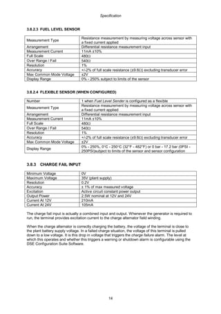
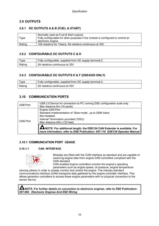
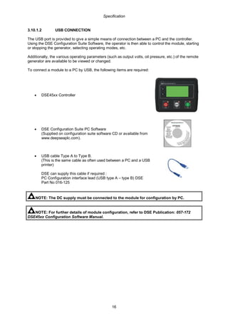
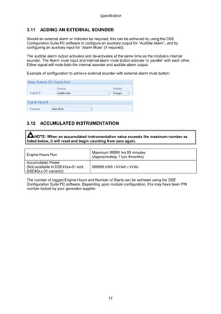
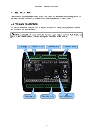
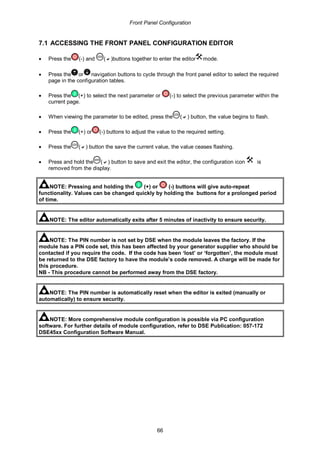
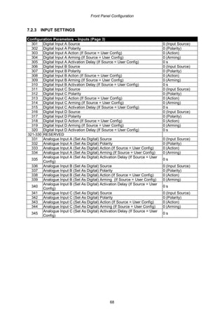
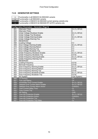
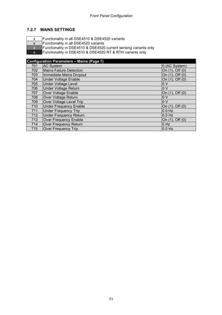
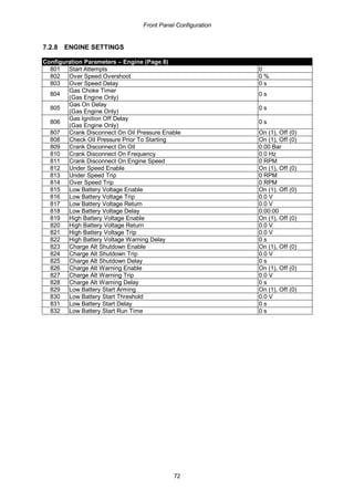
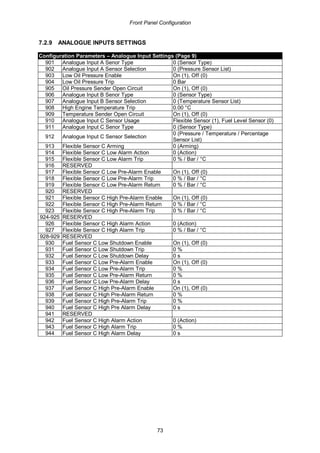
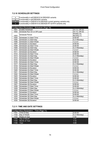
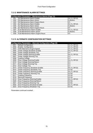
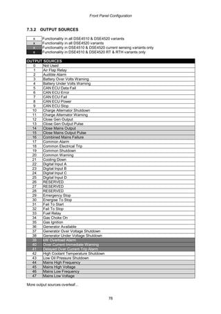
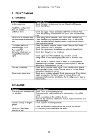
This document provides specifications and installation instructions for the DSE4510 and DSE4520 generator control modules. It includes details on terminal descriptions, wiring diagrams, earth systems, display features, and installation requirements. The document covers topics such as voltage and current sensing requirements, input and output configurations, communication ports, dimensions and mounting instructions, and applicable safety and EMC standards.
This document provides specifications and operating instructions for the DSE60xx series control module. It includes information on part numbering, power supply requirements, inputs, outputs, dimensions, applicable standards, installation, operation, the module display, front panel configuration, commissioning, fault finding, and maintenance. The DSE60xx is a generator control and instrumentation system that can automatically start and stop the engine/generator. It monitors operational parameters and indicates fault conditions on its LCD display.
This document contains a diagram of an electrical control system with labeled components including a battery, fuel solenoid, starter, sensors for oil, coolant and fuel level, and user inputs. It shows connections between the battery, controller, relays and outputs for controlling a generator, mains power, and other systems. The controller is identified as a DSE4520 and circuit breakers and terminals are indicated throughout the diagram.
This document is the operator's manual for the DSE7200/7300 series control modules. It provides specifications for the modules, including terminal specifications, voltage and current sensing capabilities, input/output options, communication protocols, dimensions, and applicable safety and EMC standards. The manual also covers installation instructions and terminal descriptions.
PERKINS 2200 SERIES 2206D-E13TA INDUSTRIAL ENGINE Service Repair Manualjsnekmse
This is the Highly Detailed factory service repair manual for thePERKINS 2200 SERIES 2206D-E13TA INDUSTRIAL ENGINE , this Service Manual has detailed illustrations as well as step by step instructions,It is 100 percents complete and intact. they are specifically written for the do-it-yourself-er as well as the experienced mechanic.PERKINS 2200 SERIES 2206D-E13TA INDUSTRIAL ENGINE Service Repair Workshop Manual provides step-by-step instructions based on the complete dis-assembly of the machine. It is this level of detail, along with hundreds of photos and illustrations, that guide the reader through each service and repair procedure. Complete download comes in pdf format which can work under all PC based windows operating system and Mac also, All pages are printable. Using this repair manual is an inexpensive way to keep your vehicle working properly.
Operation and Maintenance Manual Cover:
Safety Section
Product Information Section
Operation Section
Maintenance Section
Warranty Section
Index Section
Engine Schematic
Systems Operation Testing and Adjusting Cover:
Systems Operation Section
Testing and Adjusting Section
Fuel System
Air Inlet and Exhaust System
Lubrication System
Cooling System
Basic Engine
Electrical System
Index Section
Troubleshooting Manual Cover:
Introduction
Electronic System Overview
Configuration Parameters
Diagnostic Trouble Codes
Event Codes
Symptom Troubleshooting
Circuit Tests
Service
Index Section
File Format: PDF
Compatible: All Versions of Windows & Mac
Language: English
Requirements: Adobe PDF Reader
NO waiting, Buy from responsible seller and get INSTANT DOWNLOAD, Without wasting your hard-owned money on uncertainty or surprise! All pages are is great to havePERKINS 2200 SERIES 2206D-E13TA INDUSTRIAL ENGINE Service Repair Workshop Manual.
Looking for some other Service Repair Manual,please check:
https://www.aservicemanualpdf.com/
Thanks for visiting!
8
CASE SR200 SKID STEER LOADER Service Repair Manualjkskmdkemde
This is the Highly Detailed factory service repair manual for theCASE SR200 SKID STEER LOADER, this Service Manual has detailed illustrations as well as step by step instructions,It is 100 percents complete and intact. they are specifically written for the do-it-yourself-er as well as the experienced mechanic.CASE SR200 SKID STEER LOADER Service Repair Workshop Manual provides step-by-step instructions based on the complete dis-assembly of the machine. It is this level of detail, along with hundreds of photos and illustrations, that guide the reader through each service and repair procedure. Complete download comes in pdf format which can work under all PC based windows operating system and Mac also, All pages are printable. Using this repair manual is an inexpensive way to keep your vehicle working properly.
Service Repair Manual Covers:
Introduction
Hydraulic, Pneumatic, Electrical, Electronic System
Engine and PTO IN
Transmission, Drive and PTO OUT
Axles, Brakes and Steering
Frame and Cab
Frame Positioning
Hitch and Working Tool
Excavating and Landscaping
Schemas Index
Special Tool Index
Electrical Schematic –EH
Electrical Schematic -MECH
Hydraulic / Hydrostatic Detailed Views
File Format: PDF
Compatible: All Versions of Windows & Mac
Language: English
Requirements: Adobe PDF Reader
NO waiting, Buy from responsible seller and get INSTANT DOWNLOAD, Without wasting your hard-owned money on uncertainty or surprise! All pages are is great to haveCASE SR200 SKID STEER LOADER Service Repair Workshop Manual.
Looking for some other Service Repair Manual,please check:
https://www.aservicemanualpdf.com/
Thanks for visiting!
8
PERKINS 1106C-E70TA AND 1106D-E70TA INDUSTRIAL ENGINE (Model PV)Service Repai...jknmms ekdms
This is the Highly Detailed factory service repair manual for thePERKINS 1106C-E70TA AND 1106D-E70TA INDUSTRIAL ENGINE (MODEL PV), this Service Manual has detailed illustrations as well as step by step instructions,It is 100 percents complete and intact. they are specifically written for the do-it-yourself-er as well as the experienced mechanic.PERKINS 1106C-E70TA AND 1106D-E70TA INDUSTRIAL ENGINE (MODEL PV) Service Repair Workshop Manual provides step-by-step instructions based on the complete dis-assembly of the machine. It is this level of detail, along with hundreds of photos and illustrations, that guide the reader through each service and repair procedure. Complete download comes in pdf format which can work under all PC based windows operating system and Mac also, All pages are printable. Using this repair manual is an inexpensive way to keep your vehicle working properly.
Service Repair Manual Covers:
File Format: PDF
Compatible: All Versions of Windows & Mac
Language: English
Requirements: Adobe PDF Reader
NO waiting, Buy from responsible seller and get INSTANT DOWNLOAD, Without wasting your hard-owned money on uncertainty or surprise! All pages are is great to havePERKINS 1106C-E70TA AND 1106D-E70TA INDUSTRIAL ENGINE (MODEL PV) Service Repair Workshop Manual.
Looking for some other Service Repair Manual,please check:
https://www.aservicemanualpdf.com/
Thanks for visiting!
8
Este manual proporciona instrucciones para la instalación, reparación y mantenimiento de alternadores. Explica los reguladores de voltaje automáticos, la aplicación del alternador, la instalación en grupos electrógenos, el servicio y mantenimiento, la identificación de fallas y piezas. Cubre temas de seguridad eléctrica y requisitos de directivas y normas europeas.
This document is a service manual that describes the common rail fuel injection system for Nissan diesel engines. It provides an overview of the system components and operation, including the supply pump, rail, injectors and engine control unit. The supply pump pressurizes the fuel and controls the pressure using a suction control valve. The rail stores the high-pressure fuel. The injectors control injection timing and rate based on engine ECU commands. The ECU integrates sensor data to optimize injection for cleaner emissions and performance.
Este manual técnico fornece informações sobre a manutenção e reparo da série de motores MWM 10, incluindo dados técnicos, sistemas de lubrificação, arrefecimento e injeção, além de procedimentos de desmontagem e limpeza.
KUBOTA V3307-DI-T-E3B DIESEL ENGINE Service Repair Manualjkfkmsmmefmdm
The document provides information on identifying Kubota diesel engines. It discusses the model name, serial number, and other identification markers. The serial number indicates the month and year of manufacture. It also specifies engine dimensions and specifications for three Kubota engine models: the V2607-DI-T-E3B, V3007-DI-T-E3B, and V3307-DI-T-E3B. Safety instructions are also included for servicing the engines.
Perkins 2200 series 2206 f e13ta industrial engine (model pp3 engine)service ...jksmemd eudkmmd
This document provides safety information and troubleshooting steps for engine issues. It warns that most accidents are due to safety precautions not being followed. The hazards are identified by safety alert symbols and signals. Troubleshooting steps are provided for issues like poor acceleration, high exhaust temperature, low fuel pressure, and more. Circuit tests are also included to check components like sensors, solenoids, and control modules.
This document provides a user's guide for the TELYS control unit. It describes the standard configuration and options of the control unit, including the front and rear panels. It also outlines the main menus for actions, information, settings, and country selection. The document explains how to view alarms and faults, and view engine fault codes. It details the different access levels and exterior communication options. Finally, it provides instructions for manual and automatic operation of the generating set, as well as maintenance and troubleshooting.
This training manual provides information on servicing and maintaining the Mazda BT-50 pickup truck. It covers the key systems and components of the WL-C diesel engine, including the mechanical features, lubrication system, cooling system, intake and air system, fuel system, exhaust system, emission system, and charging and starting system. Technical specifications and part locations are provided for each system, along with overview diagrams and descriptions of important components like the variable geometry turbocharger, common rail fuel system, and EGR system.
Caterpillar Diesel Engine Control Systems [PDF, ENG, 588 KB].pdfEguima Guima
This document discusses diesel engine control systems, including engine protection and monitoring system parameters for various engine systems, as well as control systems for engines using Electronic Unit Injection (EUI) and Mechanical Unit Injection (MUI). It covers topics such as lubrication, cooling, fuel, air, exhaust, and off-engine systems; control modules; alarm modules; communication methods; and wiring considerations. The document provides an overview of the key components and considerations for diesel engine control and monitoring systems.
Jcb isuzu 4 hk1 engine service repair manualdujjsjekkekmme
This document provides service information for Isuzu 4HK1 and 6HK1 diesel engines. It includes removal and installation instructions for various engine components as well as specifications and inspection guidelines. The document covers cylinder head, camshaft, crankshaft, pistons, connecting rods, valves, timing gears, turbocharger and other parts. Precautions are provided for each procedure.
The document is a service manual for trucks that provides wiring diagrams and component information. It includes an index listing over 125 component wiring diagrams by page number. Each diagram shows the wiring for a specific component and includes symbols to identify things like connectors, fuses, splices and wire colors. The manual also includes sections with information on grounds, connectors, abbreviations and feedback.
Volvo Truck Corporation released a service bulletin providing wiring diagrams for trucks. The bulletin contains 81 pages of wiring diagrams and supporting documentation. The diagrams show electrical components, connection points, fuses, relays, and connectors. A list of 47 sub-diagrams is included, each covering a different electrical system for vehicles such as the starter, engine, lighting, and accessories.
Este documento presenta los esquemas eléctricos de varios componentes de camiones Volvo, incluyendo el sistema de arranque, la unidad electrónica de control del vehículo, el tacógrafo, el sistema de cambios, el motor, los frenos ABS, la suspensión neumática y otros sistemas. Incluye índices de los esquemas eléctricos y las ilustraciones, así como listas de fusibles, relés, conectores y abreviaturas. El propósito es proporcionar información sobre la instalación elé
Sensors and actuators are placed throughout the bus chassis. The illustration shows their locations, including components at the front (1), engine area (13), and transmission (12). Examples given are wheel speed sensors (B13, B14), engine control unit (A14), and air suspension control unit (A16). A table lists over 60 components with their designations and precise coordinates on the chassis.
Ddec iv on highway - egr application and installationeckardguendel
This document describes the hardware and wiring used in a DDEC IV engine control system for on-highway applications. It discusses the engine sensor harness, vehicle interface harness, electronic control module, sensors, and other components. Wiring diagrams and connector pinouts are provided for the harnesses connecting these components to the ECM. Environmental requirements and part numbers for components are also listed.
Este módulo introduce al estudiante al motor con tecnología ACERT C4.2, C6.4 / C4.4, C6.6. El estudiante aprenderá a identificar las etiquetas de seguridad del motor, conocerá las especificaciones técnicas de los modelos y realizará la inspección de mantenimiento siguiendo los procedimientos del manual. Completará hojas de trabajo para reforzar los conocimientos adquiridos.
This document provides technical information for repairing NEF power generation engines. It begins with an overview of the NEF engine models and applications. It then discusses fuel types, specific considerations for power generation applications, and overhaul/repair procedures. The document provides detailed instructions and diagrams to guide repairs. Safety precautions are outlined, and conversion tables are included for units of measurement.
The document provides specifications for various engine components of a D4DD engine including:
- Cylinder dimensions, compression ratio, firing order, output and torque specifications.
- Valve timing and dimensions, clearances, springs.
- Cylinder block, head and sleeve dimensions and clearances.
- Piston, ring, pin and connecting rod dimensions and clearances.
- Camshaft, crankshaft, bearing and gear dimensions and clearances.
This document provides operating instructions for Mercedes-Benz OM 904-926 LA BlueTec® diesel engines. It contains information on engine components, safety symbols, operating the engine safely and correctly, maintenance procedures, and technical specifications. The instructions emphasize using genuine Mercedes-Benz parts and servicing the engine at authorized workshops. BlueTec® engines require AdBlue® to meet emissions regulations, and operation without it can affect the engine warranty and vehicle approval.
O documento fornece especificações e valores de torque para diversos motores Mercedes-Benz, incluindo OM 314, OM 352, OM 355 e OM 904. As informações incluem dimensões do motor, sequência de ignição, folgas de válvulas, valores nominais e valores de torque para componentes como parafusos do cabeçote e mancal.
El manual de servicio incluye información sobre cómo funcionan los sistemas operativos importantes, las pruebas, las guías de ajustes y solución de problemas, así como también, los procedimientos de desarmado y armado.
El manual de piezas tiene vistas en detalle de todas las piezas de servicio del equipo. También le ofrece una guía con números para pedir piezas genuinas Caterpillar.
This document provides an overview of common rail diesel injection systems, including descriptions of key components and their operation. It discusses the supply pump, rail, injectors, control systems, diagnosis processes, and repair procedures. The supply pump pressurizes the fuel and supplies it to the high-pressure rail, which distributes it to the injectors. Electronic control modules precisely control fuel injection timing and quantity using inputs from sensors. Diagnostics involve checking codes, symptoms, and electrical circuits to isolate issues. Repair focuses on diagnosing specific systems or components causing malfunctions.
This document is an operating manual for the DSE8620 control module. It provides specifications for the module such as power supply requirements, voltage and current sensing capabilities, input/output terminal descriptions, and installation guidelines. The manual contains sections on specifications, installation, wiring diagrams and applicable safety and EMC standards.
This condition is not available on all controllers.
3.1.1.6 TEST TIME AND DATE
Allows testing of the real time clock within the controller.
Selection Description
Day Of Week Tests for a specific day of the week (Monday=1, Tuesday=2 etc.)
Day Tests for a specific day of the month (1-31)
Month Tests for a specific month (January=1, February=2 etc.)
Year Tests for a specific year
Hour Tests for a specific hour (0-23)
Minute Tests for a specific minute (0-59)
Second Tests for a specific second (0-59)
Day Of Week Mask Tests multiple days of the week using a bit mask
This document is the user manual for the KE8220 Virtual VNC Console. It contains information about FCC regulations and RoHS compliance for the device. The manual provides details on the package contents, hardware setup instructions, and component descriptions to help users install and operate the KE8220 console.
This document is a user's manual for the C850/C850D/L850/L850D laptop models. It contains 6 chapters that cover getting started, an overview of hardware components, operating basics, utilities and advanced usage, power and power-up modes, and troubleshooting. The appendices provide specifications, legal footnotes, and other supplemental information.
The document provides an owner's manual for LCD colour televisions models DU-30LZ30, DU-37LZ30, and DU-42LZ30. It contains important safety instructions, instructions for installation and connections to external devices, instructions for programming the remote control, and specifications for the televisions. The manual should be read carefully before operating the television and retained for future reference.
This document provides an overview and instructions for installing, configuring, operating, and troubleshooting the UDC2500 Universal Digital Controller. It describes the controller's displays, keys, software, mounting considerations, wiring diagrams, configuration groups and parameters, operating modes, setpoints, alarms, and tuning functions. Safety symbols are defined that are used in the document.
Chi tiết kỹ thuật máy pos BEETLE / i8A 1 và 2
Nhà phân phối: Công ty TNHH Tầm Nhìn Toàn Cầu (Global Vision Co., Ltd.)
Địa chỉ : 456/57 Cao Thắng Nối Dài, Phường 12, Quận 10, Tp.Hồ Chí Minh
Tel : (84-8) 3868 0103 / (84-8) 3868 0104
Fax : (84-8) 3868 0105
Email:sales@globalvision.com.vn
Hotline: +84 916 590 468
URL: www.globalvision.com (Global Vision Co., Ltd.)
www.wincor.com.vn (Wincor-Nixdorf Việt Nam)
This document is a service manual for Haier LCD TV models L26F6, L32F6, and L42F6. It contains warnings for technicians, including risks of electric shock and electrostatic discharge. The manual provides specifications, diagrams, disassembly/assembly instructions, component locations, installation instructions, operation instructions, and troubleshooting steps. Safety is emphasized, including using only specified replacement parts and following regulations to avoid risks to technicians and customers.
The Super Bee is InstruTech's convection enhanced Pirani vacuum gauge sensor. The CVG101 requires an external vacuum controller such as the InstruTech's VGC301, B-RAX 3000/3100 or the FlexRax 4000 to operate.
This document is the user manual for the JANDS Event 4 lighting console version 5 software. It provides instructions on hardware setup, patching, recording and playback of memories, chases and stacks. It also describes the console's menu system for configuration settings including desk mode, display options, MIDI/timecode control, and record preferences. The manual contains appendices with pinouts and a glossary of terms to assist the user in operating the console.
The document provides an overview and operation manual for the Retrotec DM32 series digital manometer blower door system. It describes the physical connections and components of the gauge, how to power it on and read results from the home screen, control fan speed and pressure, and change settings like units and averaging time. Troubleshooting tips are provided for issues like fluctuating pressure readings caused by wind or moving tubes.
This document provides installation instructions for the AP-8232 Access Point. It describes what is included in the package, features of the access point, and guidelines for hardware installation including wall or ceiling mounting and connecting power. Detailed steps are provided for installation, safety precautions, positioning the access point, and using a power injector to provide power over Ethernet. Specifications and regulatory compliance information is also included.
Communications Mining Series - Zero to Hero - Session 1DianaGray10
This session provides introduction to UiPath Communication Mining, importance and platform overview. You will acquire a good understand of the phases in Communication Mining as we go over the platform with you. Topics covered:
• Communication Mining Overview
• Why is it important?
• How can it help today’s business and the benefits
• Phases in Communication Mining
• Demo on Platform overview
• Q/A
Observability Concepts EVERY Developer Should Know -- DeveloperWeek Europe.pdfPaige Cruz
Monitoring and observability aren’t traditionally found in software curriculums and many of us cobble this knowledge together from whatever vendor or ecosystem we were first introduced to and whatever is a part of your current company’s observability stack.
While the dev and ops silo continues to crumble….many organizations still relegate monitoring & observability as the purview of ops, infra and SRE teams. This is a mistake - achieving a highly observable system requires collaboration up and down the stack.
I, a former op, would like to extend an invitation to all application developers to join the observability party will share these foundational concepts to build on:
GraphSummit Singapore | The Future of Agility: Supercharging Digital Transfor...Neo4j
Leonard Jayamohan, Partner & Generative AI Lead, Deloitte
This keynote will reveal how Deloitte leverages Neo4j’s graph power for groundbreaking digital twin solutions, achieving a staggering 100x performance boost. Discover the essential role knowledge graphs play in successful generative AI implementations. Plus, get an exclusive look at an innovative Neo4j + Generative AI solution Deloitte is developing in-house.
Climate Impact of Software Testing at Nordic Testing DaysKari Kakkonen
My slides at Nordic Testing Days 6.6.2024
Climate impact / sustainability of software testing discussed on the talk. ICT and testing must carry their part of global responsibility to help with the climat warming. We can minimize the carbon footprint but we can also have a carbon handprint, a positive impact on the climate. Quality characteristics can be added with sustainability, and then measured continuously. Test environments can be used less, and in smaller scale and on demand. Test techniques can be used in optimizing or minimizing number of tests. Test automation can be used to speed up testing.
Driving Business Innovation: Latest Generative AI Advancements & Success StorySafe Software
Are you ready to revolutionize how you handle data? Join us for a webinar where we’ll bring you up to speed with the latest advancements in Generative AI technology and discover how leveraging FME with tools from giants like Google Gemini, Amazon, and Microsoft OpenAI can supercharge your workflow efficiency.
During the hour, we’ll take you through:
Guest Speaker Segment with Hannah Barrington: Dive into the world of dynamic real estate marketing with Hannah, the Marketing Manager at Workspace Group. Hear firsthand how their team generates engaging descriptions for thousands of office units by integrating diverse data sources—from PDF floorplans to web pages—using FME transformers, like OpenAIVisionConnector and AnthropicVisionConnector. This use case will show you how GenAI can streamline content creation for marketing across the board.
Ollama Use Case: Learn how Scenario Specialist Dmitri Bagh has utilized Ollama within FME to input data, create custom models, and enhance security protocols. This segment will include demos to illustrate the full capabilities of FME in AI-driven processes.
Custom AI Models: Discover how to leverage FME to build personalized AI models using your data. Whether it’s populating a model with local data for added security or integrating public AI tools, find out how FME facilitates a versatile and secure approach to AI.
We’ll wrap up with a live Q&A session where you can engage with our experts on your specific use cases, and learn more about optimizing your data workflows with AI.
This webinar is ideal for professionals seeking to harness the power of AI within their data management systems while ensuring high levels of customization and security. Whether you're a novice or an expert, gain actionable insights and strategies to elevate your data processes. Join us to see how FME and AI can revolutionize how you work with data!
How to Get CNIC Information System with Paksim Ga.pptxdanishmna97
Pakdata Cf is a groundbreaking system designed to streamline and facilitate access to CNIC information. This innovative platform leverages advanced technology to provide users with efficient and secure access to their CNIC details.
Essentials of Automations: The Art of Triggers and Actions in FMESafe Software
In this second installment of our Essentials of Automations webinar series, we’ll explore the landscape of triggers and actions, guiding you through the nuances of authoring and adapting workspaces for seamless automations. Gain an understanding of the full spectrum of triggers and actions available in FME, empowering you to enhance your workspaces for efficient automation.
We’ll kick things off by showcasing the most commonly used event-based triggers, introducing you to various automation workflows like manual triggers, schedules, directory watchers, and more. Plus, see how these elements play out in real scenarios.
Whether you’re tweaking your current setup or building from the ground up, this session will arm you with the tools and insights needed to transform your FME usage into a powerhouse of productivity. Join us to discover effective strategies that simplify complex processes, enhancing your productivity and transforming your data management practices with FME. Let’s turn complexity into clarity and make your workspaces work wonders!
Full-RAG: A modern architecture for hyper-personalizationZilliz
Mike Del Balso, CEO & Co-Founder at Tecton, presents "Full RAG," a novel approach to AI recommendation systems, aiming to push beyond the limitations of traditional models through a deep integration of contextual insights and real-time data, leveraging the Retrieval-Augmented Generation architecture. This talk will outline Full RAG's potential to significantly enhance personalization, address engineering challenges such as data management and model training, and introduce data enrichment with reranking as a key solution. Attendees will gain crucial insights into the importance of hyperpersonalization in AI, the capabilities of Full RAG for advanced personalization, and strategies for managing complex data integrations for deploying cutting-edge AI solutions.
Best 20 SEO Techniques To Improve Website Visibility In SERPPixlogix Infotech
Boost your website's visibility with proven SEO techniques! Our latest blog dives into essential strategies to enhance your online presence, increase traffic, and rank higher on search engines. From keyword optimization to quality content creation, learn how to make your site stand out in the crowded digital landscape. Discover actionable tips and expert insights to elevate your SEO game.
Threats to mobile devices are more prevalent and increasing in scope and complexity. Users of mobile devices desire to take full advantage of the features
available on those devices, but many of the features provide convenience and capability but sacrifice security. This best practices guide outlines steps the users can take to better protect personal devices and information.
Sudheer Mechineni, Head of Application Frameworks, Standard Chartered Bank
Discover how Standard Chartered Bank harnessed the power of Neo4j to transform complex data access challenges into a dynamic, scalable graph database solution. This keynote will cover their journey from initial adoption to deploying a fully automated, enterprise-grade causal cluster, highlighting key strategies for modelling organisational changes and ensuring robust disaster recovery. Learn how these innovations have not only enhanced Standard Chartered Bank’s data infrastructure but also positioned them as pioneers in the banking sector’s adoption of graph technology.
Goodbye Windows 11: Make Way for Nitrux Linux 3.5.0!SOFTTECHHUB
As the digital landscape continually evolves, operating systems play a critical role in shaping user experiences and productivity. The launch of Nitrux Linux 3.5.0 marks a significant milestone, offering a robust alternative to traditional systems such as Windows 11. This article delves into the essence of Nitrux Linux 3.5.0, exploring its unique features, advantages, and how it stands as a compelling choice for both casual users and tech enthusiasts.
“An Outlook of the Ongoing and Future Relationship between Blockchain Technologies and Process-aware Information Systems.” Invited talk at the joint workshop on Blockchain for Information Systems (BC4IS) and Blockchain for Trusted Data Sharing (B4TDS), co-located with with the 36th International Conference on Advanced Information Systems Engineering (CAiSE), 3 June 2024, Limassol, Cyprus.
Why You Should Replace Windows 11 with Nitrux Linux 3.5.0 for enhanced perfor...SOFTTECHHUB
The choice of an operating system plays a pivotal role in shaping our computing experience. For decades, Microsoft's Windows has dominated the market, offering a familiar and widely adopted platform for personal and professional use. However, as technological advancements continue to push the boundaries of innovation, alternative operating systems have emerged, challenging the status quo and offering users a fresh perspective on computing.
One such alternative that has garnered significant attention and acclaim is Nitrux Linux 3.5.0, a sleek, powerful, and user-friendly Linux distribution that promises to redefine the way we interact with our devices. With its focus on performance, security, and customization, Nitrux Linux presents a compelling case for those seeking to break free from the constraints of proprietary software and embrace the freedom and flexibility of open-source computing.
For the full video of this presentation, please visit: https://www.edge-ai-vision.com/2024/06/building-and-scaling-ai-applications-with-the-nx-ai-manager-a-presentation-from-network-optix/
Robin van Emden, Senior Director of Data Science at Network Optix, presents the “Building and Scaling AI Applications with the Nx AI Manager,” tutorial at the May 2024 Embedded Vision Summit.
In this presentation, van Emden covers the basics of scaling edge AI solutions using the Nx tool kit. He emphasizes the process of developing AI models and deploying them globally. He also showcases the conversion of AI models and the creation of effective edge AI pipelines, with a focus on pre-processing, model conversion, selecting the appropriate inference engine for the target hardware and post-processing.
van Emden shows how Nx can simplify the developer’s life and facilitate a rapid transition from concept to production-ready applications.He provides valuable insights into developing scalable and efficient edge AI solutions, with a strong focus on practical implementation.
Programming Foundation Models with DSPy - Meetup SlidesZilliz
Prompting language models is hard, while programming language models is easy. In this talk, I will discuss the state-of-the-art framework DSPy for programming foundation models with its powerful optimizers and runtime constraint system.
6. Bibliography
6
1 BIBLIOGRAPHY
This document refers to and is referred to by the following DSE publications which can be obtained
from the DSE website: www.deepseaplc.com
1.1 INSTALLATION INSTRUCTIONS
Installation instructions are supplied with the product in the box and are intended as a ‘quick start’
guide only.
DSE Part Description
053-145 DSE4510 & DSE4520 Installation Instructions
1.2 TRAINING GUIDES
Training Guides are produced to give ‘handout’ sheets on specific subjects during training sessions
DSE Part Description
056-005 Using CTs With DSE Products
056-010 Over Current Protection
056-022 Breaker Control
056-029 Smoke Limiting
056-030 Module PIN Codes
1.3 MANUALS
Product manuals are can be downloaded from the DSE website: www.deepseaplc.com
DSE Part Description
057-004 Electronic Engines and DSE Wiring Guide
057-172 DSE45xx Configuration Suite PC Software Manual
1.4 THIRD PARTY DOCUMENTS
The following third party documents are also referred to:
Reference Description
ISBN 1-55937-879-4
IEEE Std C37.2-1996 IEEE Standard Electrical Power System Device Function
Numbers and Contact Designations. Institute of Electrical and Electronics Engineers Inc
ISBN 0-7506-1147-2 Diesel generator handbook. L.L.J. Mahon
ISBN 0-9625949-3-8 On-Site Power Generation. EGSA Education Committee.
7. Introduction
7
2 INTRODUCTION
This document details the installation and operation requirements of the DSE4510 & DSE4520
modules, part of the DSEGenset® range of products.
The manual forms part of the product and should be kept for the entire life of the product. If the
product is passed or supplied to another party, ensure that this document is passed to them for
reference purposes.
This is not a controlled document. You will not be automatically informed of updates. Any future
updates of this document will be included on the DSE website at www.deepseaplc.com
The DSE4xxx series is designed to provide differing levels of functionality across a common
platform. This allows the generator OEM greater flexibility in the choice of controller to use for a
specific application.
The DSE45xx series module has been designed to allow the operator to start and stop the generator,
and if required, transfer the load to the generator either manually or automatically. Additionally, the
DSE4520 automatically starts and stops the generator set depending upon the status of the mains
(utility) supply.
The user also has the facility to view the system operating parameters via the LCD display.
The DSE45xx module monitors the engine, indicating the operational status and fault conditions,
automatically shutting down the engine and giving a true first up fault condition of an engine failure
by the LCD display.
The powerful ARM microprocessor contained within the module allows for incorporation of a range of
complex features:
• Icon based LCD display
• True RMS Voltage
• Current and Power monitoring (Not Available on DSE45xx-01 and DSE45xx-31 variants)
• USB Communications
• Engine parameter monitoring.
• Fully configurable inputs for use as alarms or a range of different functions.
• Engine ECU interface to electronic engines.
Using a PC and the DSE Configuration Suite software allows alteration of selected operational
sequences, timers, alarms and operational sequences. Additionally, the module’s integral front panel
configuration editor allows adjustment of this information.
A robust plastic case designed for front panel mounting houses the module. Connections are via
locking plug and sockets.
Access to critical operational sequences and timers for use by qualified engineers, can be protected
by a security code. Module access can also be protected by PIN code. Selected parameters can be
changed from the module’s front panel.
The module is housed in a robust plastic case suitable for panel mounting. Connections to the
module are via locking plug and sockets.
8. Specification
8
3 SPECIFICATIONS
3.1 PART NUMBERING
4510 - 002 - 01
3.1.1 SHORT NAMES
Short Name Description
DSE4000,DSE4xxx All modules in the DSE4000 range.
DSE4500,DSE45xx All modules in the DSE4500 range.
DSE4510 DSE4510 module/controller
DSE4520 DSE4520 module/controller
3.2 OPERATING TEMPERATURE
Module Description
DSE45xx -30ºC to +70ºC (-40ºC to +70ºC for variants fitted with display heaters)
Variant
Hardware Revision
With Conformal Coating, Real
Time Clock, Heated Display &
Current Sensing
Product Type
DSE4520
Auto Mains Failure
Controller
4520
Without Current Sensing 01
Initial 001
DSE4510
Autostart Controller
4510
With Current Sensing 02
With Conformal Coating &
Without Current Sensing
31
With Conformal Coating &
Current Sensing
32
Added Support for Display Heater 002
With Real Time Clock
& Current Sensing 03
With Real Time Clock, Heated
Display & Current Sensing
04
With Conformal Coating, Real
Time Clock & Current Sensing
33
34
9. Specification
9
3.3 REQUIREMENTS FOR UL CERTIFICATION
Screw Terminal
Tightening
Torque
• 4.5 lb-in (0.5 Nm)
Conductors
• Terminals suitable for connection of conductor size 12 AWG – 26 AWG
(0.5mm² to 2.0mm²).
• Conductor protection must be provided in accordance with NFPA 70, Article
240
• Low voltage circuits (35 volts or less) must be supplied from the engine
starting battery or an isolated secondary circuit.
• The communication, sensor, and/or battery derived circuit conductors shall be
separated and secured to maintain at least ¼” (6mm) separation from the
generator and mains connected circuit conductors unless all conductors are
rated 600 Volts or greater.
Current Inputs
• Must be connected through UL Listed or Recognized isolating current
transformers with the secondary rating of 5A max.
Communication
Circuits
• Must be connected to communication circuits of UL Listed equipment
Output Pilot Duty • 0.5 A
Mounting
• Suitable for use in type 1 Enclosure Type rating with surrounding air
temperature -22ºF to +158ºF (-30ºC to +70ºC)
• Suitable for pollution degree 3 environments when voltage sensing inputs do
not exceed 300V. When used to monitor voltages over 300V device to be
install in an unventilated or filtered ventilation enclosure to maintain a pollution
degree 2 environment.
Operating
Temperature
• -22ºF to +158ºF (-30ºC to +70ºC)
Storage
Temperature
• -40ºF to +176ºF (-40ºC to +80ºC)
3.4 TERMINAL SPECIFICATION
NOTE: For purchasing additional connector plugs from DSE, please see the section
entitled Maintenance, Spares, Repair and Servicing elsewhere in this document.
Connection Type
Two part connector.
• Male part fitted to
module
• Female part supplied in
module packing case -
Screw terminal, rising
clamp, no internal
spring.
Example showing cable entry and screw
terminals of a 10 way connector
Minimum Cable Size 0.5mm² (AWG 24)
Maximum Cable Size 2.5mm² (AWG 10)
10. Specification
10
3.5 POWER SUPPLY REQUIREMENTS
Minimum Supply Voltage 8V continuous
Cranking Dropouts
Able to survive 0V for 100ms providing the supply was at least
10V before the dropout and recovers to 5V afterwards.
Maximum Supply Voltage 35V continuous (60V protection)
Reverse Polarity Protection -35V continuous
Maximum Operating Current
96mA at12V
85mA at 24V
Maximum Standby Current
51mA at 12V
47mA at 24V
Maximum Current When In
Sleep Mode
35mA at 12V
32mA at 24V
Maximum Current When In
Deep Sleep Mode
Less than 10µA at 12V
Less than 10µA at 24V
3.5.1 MODULE SUPPLY INSTRUMENTATION DISPLAY
Range 0V-70V DC (note Maximum continuous operating voltage of 35V DC)
Resolution 0.1V
Accuracy 1% full scale (±0.7V)
3.6 VOLTAGE & FREQUENCY SENSING
Measurement Type True RMS conversion
Sample Rate 5kHz or better
Harmonics Up to 11th
or better
Input Impedance 300kΩ phase to neutral
Phase To Neutral
15V (minimum required for sensing frequency) to 415V AC (absolute maximum)
Suitable for 345V nominal
(±20% for under/overvoltage detection)
Phase To Phase
25V (minimum required for sensing frequency) to 720V AC (absolute maximum)
Suitable for 600V nominal
(±20% for under/overvoltage detection)
Common Mode Offset From Earth 100V AC (max)
Resolution
1V AC phase to neutral
2V AC phase to phase
Accuracy
±1% of full scale phase to neutral
±2% of full scale phase to phase
Minimum Frequency 3.5 Hz
Maximum Frequency 75.0 Hz
Frequency Resolution 0.1 Hz
Frequency Accuracy ±0.2 Hz
11. Specification
11
3.7 CURRENT SENSING
NOTE: Current Sensing is not available on DSE45xx-01 and DSE45xx-31 variants.
Measurement Type True RMS conversion
Sample Rate 5KHz or better
Harmonics Up to 10th
or better
Nominal CT Secondary Rating 5A
Maximum Continuous Current 5A
Overload Measurement 3 x Nominal Range setting
Absolute Maximum Overload 50A for 1 second
Burden 0.25VA (0.01Ω current shunts)
Common Mode Offset ±1V peak plant ground to CT common terminal
Resolution 0.5% of 5A
Accuracy ±1% of Nominal (5A) (excluding CT error)
3.7.1 VA RATING OF THE CTS
The VA burden of the module on the CTs is 0.5VA. However depending upon the type and length of
cabling between the CTs and the module, CTs with a greater VA rating than the module are required.
The distance between the CTs and the
measuring module should be
estimated and cross-referenced
against the chart opposite to find the
VA burden of the cable itself.
If the CTs are fitted within the
alternator top box, the star point
(common) of the CTs should be
connected to system ground (earth) as
close as possible to the CTs. This
minimises the length of cable used to
connect the CTs to the DSE module.
Example.
If 1.5mm² cable is used and the
distance from the CT to the measuring
module is 20m, then the burden of the
cable alone is approximately 15VA. As
the burden of the DSE controller is
0.5VA, then a CT with a rating of at
least 15+0.5V = 15.5VA must be used.
If 2.5mm² cables are used over the
same distance of 20m, then the
burden of the cable on the CT is
approximately 7VA. CT’s required in
this instance is at least 7.5VA (7+0.5).
NOTE: Details for 4mm² cables are shown for reference only. The connectors on the DSE
modules are only suitable for cables up to 2.5mm².
12. Specification
12
3.7.2 CT POLARITY
NOTE: Take care to ensure correct polarity of the CT primary as shown above. If in doubt,
check with the CT supplier.
Take care to ensure the correct polarity of the CTs. Incorrect CT orientation will lead to negative kW
readings when the set is supplying power. Take note that paper stick-on labels on CTs that show the
orientation are often incorrectly placed on the CT (!). It is more reliable to use the labelling in the
case moulding as an indicator to orientation (if available).
To test orientation, run the generator in island mode (not in parallel with any other supply) and load
the generator to around 10% of the set rating. Ensure the DSE module shows positive kW for all
three individual phase readings.
TO GENERATOR TO LOAD
POLARITY OF CT PRIMARY
3.7.3 CT PHASING
Take particular care that the CTs are connected to the correct phases. For instance, ensure that the
CT on phase 1 is connected to the terminal on the DSE module intended for connection to the CT for
phase 1.
Additionally ensure that the voltage sensing for phase 1 is actually connected to generator phase 1.
Incorrect connection of the phases as described above will result in incorrect power factor (pf)
measurements, which in turn results in incorrect kW measurements.
One way to check for this is to make use of a single-phase load. Place the load on each phase in
turn, run the generator and ensure the kW value appears in the correct phase. For instance if the
load is connected to phase 3, ensure the kW figure appears in phase 3 display and not in the display
for phase 1 or 2.
3.7.4 CT CLASS
Ensure the correct CT type is chosen. For instance if the DSE module is providing overcurrent
protection, ensure the CT is capable of measuring the overload level you wish to protect against, and
at the accuracy level you require.
For instance, this may mean fitting a protection class CT (P10 type) to maintain high accuracy while
the CT is measuring overload currents.
Conversely, if the DSE module is using the CT for instrumentation only (current protection is disabled
or not fitted to the controller), then measurement class CTs can be used. Again, bear in mind the
accuracy you require. The DSE module is accurate to better than 1% of the full-scale current reading.
To maintain this accuracy you should fit Class 0.5 or Class 1 CTs.
You should check with your CT manufacturer for further advice on selecting your CTs
labelled as p1,
k or K
labelled as p2,
l or L
13. Specification
13
3.8 INPUTS
3.8.1 DIGITAL INPUTS
Number
4 configurable digital inputs
(7 when Analogue Inputs are configured as digital inputs)
Arrangement Contact between terminal and ground
Low Level Threshold 3.2V minimum
High Level Threshold 8.1V maximum
Maximum Input Voltage +60V DC with respect to plant supply negative
Minimum Input Voltage -24V DC with respect to plant supply negative
Contact Wetting Current 6mA typical
Open Circuit Voltage 15V typical
3.8.2 ANALOGUE INPUTS
3.8.2.1 OIL PRESSURE
Measurement Type
Resistance measurement by measuring voltage across sensor with a
fixed current applied
Arrangement Differential resistance measurement input
Measurement Current 11mA ±10%
Full Scale 240Ω
Over Range / Fail 270Ω
Resolution 0.1 Bar (1-2 PSI)
Accuracy ±2% of full scale resistance (±4.8Ω) excluding transducer error
Max Common Mode Voltage ±2V
Display Range 0 bar - 17.2 bar (0PSI - 250PSI) subject to limits of the sensor
3.8.2.2 COOLANT TEMPERATURE
Measurement Type
Resistance measurement by measuring voltage across sensor with a
fixed current applied
Arrangement Differential resistance measurement input
Measurement Current 11mA ±10%
Full Scale 480Ω
Over Range / Fail 540Ω
Resolution 1°C (2°F)
Accuracy +/-2% of full scale resistance (±9.6Ω) excluding transducer error
Max Common Mode Voltage ±2V
Display Range 0°C - 250°C (32°F - 482°F) subject to limits of the sensor
14. Specification
14
3.8.2.3 FUEL LEVEL SENSOR
Measurement Type
Resistance measurement by measuring voltage across sensor with
a fixed current applied
Arrangement Differential resistance measurement input
Measurement Current 11mA ±10%
Full Scale 480Ω
Over Range / Fail 540Ω
Resolution 1%
Accuracy +/-2% of full scale resistance (±9.6Ω) excluding transducer error
Max Common Mode Voltage ±2V
Display Range 0% - 250% subject to limits of the sensor
3.8.2.4 FLEXIBLE SENSOR (WHEN CONFIGURED)
Number 1 when Fuel Level Sender is configured as a flexible
Measurement Type
Resistance measurement by measuring voltage across sensor with
a fixed current applied
Arrangement Differential resistance measurement input
Measurement Current 11mA ±10%
Full Scale 480Ω
Over Range / Fail 540Ω
Resolution 1%
Accuracy +/-2% of full scale resistance (±9.6Ω) excluding transducer error
Max Common Mode Voltage ±2V
Display Range
0% - 250%, 0°C - 250°C (32°F - 482°F) or 0 bar - 17.2 bar (0PSI -
250PSI)subject to limits of the sensor and sensor configuration
3.8.3 CHARGE FAIL INPUT
Minimum Voltage 0V
Maximum Voltage 35V (plant supply)
Resolution 0.2V
Accuracy ± 1% of max measured voltage
Excitation Active circuit constant power output
Output Power 2.5W nominal at 12V and 24V
Current At 12V 210mA
Current At 24V 105mA
The charge fail input is actually a combined input and output. Whenever the generator is required to
run, the terminal provides excitation current to the charge alternator field winding.
When the charge alternator is correctly charging the battery, the voltage of the terminal is close to
the plant battery supply voltage. In a failed charge situation, the voltage of this terminal is pulled
down to a low voltage. It is this drop in voltage that triggers the charge failure alarm. The level at
which this operates and whether this triggers a warning or shutdown alarm is configurable using the
DSE Configuration Suite Software.
15. Specification
15
3.9 OUTPUTS
3.9.1 DC OUTPUTS A & B (FUEL & START)
Type
Normally used as Fuel & Start outputs.
Fully configurable for other purposes if the module is configured to control an
electronic engine.
Rating 10A resistive for 10secs, 5A resistive continuous at 35V
3.9.2 CONFIGURABLE DC OUTPUTS C & D
Type Fully configurable, supplied from DC supply terminal 2.
Rating 2A resistive continuous at 35V
3.9.3 CONFIGURABLE DC OUTPUTS E & F (DSE4520 ONLY)
Type Fully configurable, supplied from DC supply terminal 2.
Rating 2A resistive continuous at 35V
3.10 COMMUNICATION PORTS
USB Port
USB 2.0 Device for connection to PC running DSE configuration suite only.
Max distance 6m (18 yards)
CAN Port
Engine CAN Port
Standard implementation of ‘Slow mode’, up to 250K bits/s
Non-Isolated.
Internal Termination provided (120Ω)
Max distance 40m (133 feet)
NOTE: For additional length, the DSE124 CAN Extender is available. For
more information, refer to DSE Publication: 057-116 DSE124 Operator Manual
3.10.1 COMMUNICATION PORT USAGE
3.10.1.1 CAN INTERFACE
Modules are fitted with the CAN interface as standard and are capable of
receiving engine data from engine CAN controllers compliant with the
CAN standard.
CAN enabled engine controllers monitor the engine’s operating
parameters such as engine speed, oil pressure, engine temperature
(among others) in order to closely monitor and control the engine. The industry standard
communications interface (CAN) transports data gathered by the engine controller interface. This
allows generator controllers to access these engine parameters with no physical connection to the
sensor device.
NOTE: For further details on connection to electronic engines, refer to DSE Publication:
057-004 Electronic Engines And DSE Wiring
16. Specification
16
3.10.1.2 USB CONNECTION
The USB port is provided to give a simple means of connection between a PC and the controller.
Using the DSE Configuration Suite Software, the operator is then able to control the module, starting
or stopping the generator, selecting operating modes, etc.
Additionally, the various operating parameters (such as output volts, oil pressure, etc.) of the remote
generator are available to be viewed or changed.
To connect a module to a PC by USB, the following items are required:
• DSE45xx Controller
• DSE Configuration Suite PC Software
(Supplied on configuration suite software CD or available from
www.deepseaplc.com).
• USB cable Type A to Type B.
(This is the same cable as often used between a PC and a USB
printer)
DSE can supply this cable if required :
PC Configuration interface lead (USB type A – type B) DSE
Part No 016-125
NOTE: The DC supply must be connected to the module for configuration by PC.
NOTE: For further details of module configuration, refer to DSE Publication: 057-172
DSE45xx Configuration Software Manual.
17. Specification
17
3.11 ADDING AN EXTERNAL SOUNDER
Should an external alarm or indicator be required, this can be achieved by using the DSE
Configuration Suite PC software to configure an auxiliary output for “Audible Alarm”, and by
configuring an auxiliary input for “Alarm Mute” (if required).
The audible alarm output activates and de-activates at the same time as the module’s internal
sounder. The Alarm mute input and internal alarm mute button activate ‘in parallel’ with each other.
Either signal will mute both the internal sounder and audible alarm output.
Example of configuration to achieve external sounder with external alarm mute button:
3.12 ACCUMULATED INSTRUMENTATION
NOTE: When an accumulated instrumentation value exceeds the maximum number as
listed below, it will reset and begin counting from zero again.
Engine Hours Run
Maximum 99999 hrs 59 minutes
(Approximately 11yrs 4months)
Accumulated Power
(Not available in DSE45xx-01 and
DSE45xx-31 variants)
999999 kWh / kVArh / kVAh
The number of logged Engine Hours and Number of Starts can be set/reset using the DSE
Configuration Suite PC software. Depending upon module configuration, this may have been PIN
number locked by your generator supplier
18. Specification
18
3.13 DIMENSIONS AND MOUNTING
3.13.1 DIMENSIONS
140.0mm x 113mm x 43mm
(5.5” x 4.4” x 1.7”)
3.13.2 PANEL CUTOUT
118mm x 92mm
(4.6” x 3.6”)
3.13.3 WEIGHT
0.16kg
(0.35lb)
19. Specification
19
3.13.4 FIXING CLIPS
The module is held into the panel fascia using the supplied fixing clips.
• Withdraw the fixing clip screw (turn anticlockwise) until only the pointed end is protruding
from the clip.
• Insert the three ‘prongs’ of the fixing clip into the slots in the side of the module case.
• Pull the fixing clip backwards (towards the back of the module) ensuring all three prongs of
the clip are inside their allotted slots.
• Turn the fixing clip screws clockwise until they make contact with the panel fascia.
• Turn the screws a little more to secure the module into the panel fascia. Care should be
taken not to over tighten the fixing clip screws.
NOTE: In conditions of excessive vibration, mount the module on suitable anti-vibration
mountings.
Fixing clip
fitted to module
Fixing clip
20. Specification
20
3.13.5 SILICON SEALING GASKET
NOTE: For purchasing an additional silicon gasket from DSE, please see the section
entitled Maintenance, Spares, Repair and Servicing elsewhere in this document.
The optional silicon gasket provides improved sealing between module and the panel fascia.
The gasket is fitted to the module before installation into the panel fascia.
Take care to ensure the gasket is correctly fitted to the module to maintain the integrity of the seal.
Gasket fitted
to module
Sealing gasket
21. Specification
21
3.13.6 APPLICABLE STANDARDS
BS 4884-1 This document conforms to BS4884-1 1992 Specification for
presentation of essential information.
BS 4884-2 This document conforms to BS4884-2 1993 Guide to content
BS 4884-3 This document conforms to BS4884-3 1993 Guide to presentation
BS EN 60068-2-1
(Minimum temperature)
-30°C (-22°F)
BS EN 60068-2-2
(Maximum temperature)
+70°C (158°F)
BS EN 60950 Safety of information technology equipment, including electrical
business equipment
BS EN 61000-6-2 EMC Generic Immunity Standard (Industrial)
BS EN 61000-6-4 EMC Generic Emission Standard (Industrial)
BS EN 60529
(Degrees of protection
provided by enclosures)
IP65 (front of module when installed into the control panel with the
optional sealing gasket)
IP42 (front of module when installed into the control panel WITHOUT
being sealed to the panel)
UL508
NEMA rating
(Approximate)
12 (Front of module when installed into the control panel with the
supplied sealing gasket).
2 (Front of module when installed into the control panel WITHOUT being
sealed to the panel)
IEEE C37.2
(Standard Electrical
Power System Device
Function Numbers and
Contact Designations)
Under the scope of IEEE 37.2, function numbers can also be used to
represent functions in microprocessor devices and software programs.
The controller is device number 11L-8000 (Multifunction device
protecting Line (generator) –module).
As the module is configurable by the generator OEM, the functions
covered by the module will vary. Under the module’s factory
configuration, the device numbers included within the module are :
2 – Time Delay Starting Or Closing Relay
3 – Checking Or Interlocking Relay
5 – Stopping Device
6 – Starting Circuit Breaker
8 – Control Power Disconnecting Device
10 – Unit Sequence Switch
11 – Multifunction Device
12 – Overspeed Device
14 – Underspeed Device
26 – Apparatus Thermal Device
27AC – AC Undervoltage Relay
27DC – DC Undervoltage Relay
29 – Isolating Contactor Or Switch
30 – Annunciator Relay
31 – Separate Excitation Device
42 – Running Circuit Breaker
Continued overleaf...
22. Specification
22
IEEE C37.2
(Standard Electrical
Power System Device
Function Numbers and
Contact Designations)
Continued
50 – Instantaneous Overcurrent Relay
52 – AC Circuit Breaker
53 – Exciter Or DC Generator Relay
54 – Turning Gear Engaging Device
59AC – AC Overvoltage Relay
59DC – DC Overvoltage Relay
62 – Time Delay Stopping Or Opening Relay
63 – Pressure Switch
71 – Level Switch
74 – Alarm Relay
81 – Frequency Relay
83 – Automatic Selective Control Or Transfer Relay
86 – Lockout Relay
In line with our policy of continual development, Deep Sea Electronics, reserve the right to change specification without notice.
23. Specification
23
3.13.7 ENCLOSURE CLASSIFICATIONS
3.13.7.1 IP CLASSIFICATIONS
The modules specification under BS EN 60529 Degrees of protection provided by enclosures
IP65 (Front of module when module is installed into the control panel with the optional sealing gasket).
IP42 (front of module when module is installed into the control panel WITHOUT being sealed to the panel)
First Digit Second Digit
Protection against contact and ingress of solid objects Protection against ingress of water
0 No protection 0 No protection
1 Protected against ingress solid objects with a
diameter of more than 50 mm. No protection against
deliberate access, e.g. with a hand, but large surfaces
of the body are prevented from approach.
1 Protection against dripping water falling vertically. No harmful
effect must be produced (vertically falling drops).
2 Protected against penetration by solid objects with a
diameter of more than 12 mm. Fingers or similar
objects prevented from approach.
2 Protection against dripping water falling vertically. There
must be no harmful effect when the equipment (enclosure) is
tilted at an angle up to 15° from its normal position (drops
falling at an angle).
3 Protected against ingress of solid objects with a
diameter of more than 2.5 mm. Tools, wires etc. with
a thickness of more than 2.5 mm are prevented from
approach.
3 Protection against water falling at any angle up to 60° from
the vertical. There must be no harmful effect (spray water).
4 Protected against ingress of solid objects with a
diameter of more than 1 mm. Tools, wires etc. with a
thickness of more than 1 mm are prevented from
approach.
4 Protection against water splashed against the equipment
(enclosure) from any direction. There must be no harmful
effect (splashing water).
5 Protected against harmful dust deposits. Ingress of
dust is not totally prevented but the dust must not
enter in sufficient quantity to interface with
satisfactory operation of the equipment. Complete
protection against contact.
5 Protection against water projected from a nozzle against the
equipment (enclosure) from any direction. There must be no
harmful effect (water jet).
6 Protection against ingress of dust (dust tight).
Complete protection against contact.
6 Protection against heavy seas or powerful water jets. Water
must not enter the equipment (enclosure) in harmful
quantities (splashing over).
24. Specification
24
3.13.7.2 NEMA CLASSIFICATIONS
THE MODULES NEMA RATING (APPROXIMATE)
12 (Front of module when module is installed into the control panel with the optional sealing gasket).
2 (front of module when module is installed into the control panel WITHOUT being sealed to the panel)
NOTE: There is no direct equivalence between IP / NEMA ratings. IP figures shown are
approximate only.
1
IP30
Provides a degree of protection against contact with the enclosure equipment and against a limited amount of falling dirt.
2
IP31
Provides a degree of protection against limited amounts of falling water and dirt.
3
IP64
Provides a degree of protection against windblown dust, rain and sleet; undamaged by the formation of ice on the
enclosure.
3R
IP32
Provides a degree of protection against rain and sleet:; undamaged by the formation of ice on the enclosure.
4 (X)
IP66
Provides a degree of protection against splashing water, windblown dust and rain, hose directed water; undamaged by the
formation of ice on the enclosure. (Resist corrosion).
12/12K
IP65
Provides a degree of protection against dust, falling dirt and dripping non corrosive liquids.
13
IP65
Provides a degree of protection against dust and spraying of water, oil and non corrosive coolants.
25. Installation – Terminal Description
25
4 INSTALLATION
The module is designed to be mounted on the panel fascia. For dimension and mounting details, see
the section entitled Specification, Dimension and mounting elsewhere in this document.
4.1 TERMINAL DESCRIPTION
To aid user connection, icons are used on the rear of the module to help identify terminal functions.
An example of this is shown below.
NOTE: Availability of some terminals depends upon module version. Full details are
given in the section entitled Terminal Description elsewhere in this manual.
Terminals 1-9 Terminals 10-20
Terminals 21-24 Terminals 29-32
USB
PC Configuration
Terminals 25-28UL Ratings
26. Installation – Terminal Description
26
4.1.1 DC SUPPLY, FUEL AND START OUTPUTS, OUTPUTS C, D, E & F
Pin
No
Description Cable Size Notes
1
DC Plant Supply Input
(Negative)
2.5mm²
AWG 13
2
DC Plant Supply Input
(Positive)
2.5 mm²
AWG 13
Supplies the module and DC Outputs A, B, C, D, E & F
3 DC Output A (FUEL)
2.5mm²
AWG 13
Plant Supply Positive from terminal 2.
10A for 10secs, 5A resistive continuous
Fixed as FUEL relay if electronic engine is not configured.
4 DC Output B (START)
2.5mm²
AWG 13
Plant Supply Positive from terminal 2.
10A for 10secs, 5A resistive continuous
Fixed as START relay if electronic engine is not configured.
5 Charge Fail / Excite
2.5mm²
AWG 13
Do not connect to ground (battery negative).
If charge alternator is not fitted, leave this terminal
disconnected.
6 DC Output C
1.0mm²
AWG 18
Plant Supply Positive from terminal 2. 2 Amp rated.
7 DC Output D
1.0mm²
AWG 18
Plant Supply Positive from terminal 2. 2 Amp rated.
8 DC Output E
1.0mm²
AWG 18
Plant Supply Positive from terminal 2. 2 Amp rated.
9 DC Output F
1.0mm²
AWG 18
Plant Supply Positive from terminal 2. 2 Amp rated.
NOTE: Terminals 8 & 9 are not fitted to DSE4510 controller.
NOTE: When the module is configured for operation with an electronic engine, FUEL and
START output requirements may be different. For further details on connection to electronic
engines, refer to DSE Publication: 057-004 Electronic Engines And DSE Wiring
NOTE: For further details of module configuration, refer to DSE Publication: 057-172
DSE45xx Configuration Software Manual.
27. Installation – Terminal Description
27
4.1.2 ANALOGUE SENSOR
Pin
No
Description
Cable
Size
Notes
10 Sensor Common Return
0.5mm²
AWG 20
Return Feed For Sensors
11 Oil Pressure Input
0.5mm²
AWG 20
Connect To Oil Pressure Sensor
12 Coolant Temperature Input
0.5mm²
AWG 20
Connect To Coolant Temperature Sensor
13 Fuel Level Input
0.5mm²
AWG 20
Connect To Fuel Level Sensor
NOTE: It is VERY important that terminal 10 (sensor common) is soundly connected to an
earth point on the ENGINE BLOCK, not within the control panel, and must be a sound
electrical connection to the sensor bodies. This connection MUST NOT be used to provide an
earth connection for other terminals or devices. The simplest way to achieve this is to run a
SEPARATE earth connection from the system earth star point, to terminal 10 directly, and not
use this earth for other connections.
NOTE: If you use PTFE insulating tape on the sensor thread when using earth return
sensors, ensure you do not insulate the entire thread, as this will prevent the sensor body
from being earthed via the engine block.
NOTE: For further details of module configuration, refer to DSE Publication: 057-172
DSE45xx Configuration Software Manual.
28. Installation – Terminal Description
28
4.1.3 CONFIGURABLE DIGITAL INPUTS & CAN
Pin
No
Description
Cable
Size
Notes
14 Configurable Digital Input A
0.5mm²
AWG 20
Switch to negative
15 Configurable Digital Input B
0.5mm²
AWG 20
Switch to negative
16 Configurable Digital Input C
0.5mm²
AWG 20
Switch to negative
17 Configurable Digital Input D
0.5mm²
AWG 20
Switch to negative
18 CAN Port H
0.5mm²
AWG 20
Use only 120Ω CAN approved cable
19 CAN Port L
0.5mm²
AWG 20
Use only 120Ω CAN approved cable
20 CAN Port Screen Shield Use only 120Ω CAN approved cable
NOTE: For further details of module configuration, refer to DSE Publication: 057-172
DSE45xx Configuration Software Manual.
NOTE: For further details on connection to electronic engines, refer to DSE Publication:
057-004 Electronic Engines And DSE Wiring
NOTE: Screened 120ΩΩΩΩ impedance cable specified for use with CAN must be used for the
CAN link.
DSE stock and supply Belden cable 9841 which is a high quality 120ΩΩΩΩ impedance cable
suitable for CAN use (DSE part number 016-030)
4.1.4 GENERATOR / MAINS VOLTAGE & FREQUENCY SENSING
Pin
No
Description
Cable
Size
Notes
21 Generator L1 (U) Voltage Monitoring
1.0mm²
AWG 18
Connect to generator L1 (U) output (AC)
(Recommend 2A fuse)
22 Generator L2 (V) Voltage Monitoring
1.0mm²
AWG 18
Connect to generator L2 (V) output (AC)
(Recommend 2A fuse)
23 Generator L3 (W) Voltage Monitoring
1.0mm²
AWG 18
Connect to generator L3 (W) output (AC)
(Recommend 2A fuse)
24 Generator Neutral (N) Input
1.0mm²
AWG 18
Connect to generator Neutral terminal (AC)
25 Mains L1 (R) Voltage Monitoring
1.0mm²
AWG 18
Connect to Mains L1 (R) output (AC)
(Recommend 2A fuse)
26 Mains L2 (S) Voltage Monitoring
1.0mm²
AWG 18
Connect to Mains L2 (S) output (AC)
(Recommend 2A fuse)
27 Mains L3 (T) Voltage Monitoring
1.0mm²
AWG 18
Connect to Mains L3 (T) output (AC)
(Recommend 2A fuse)
28 Mains Neutral (N) Input
1.0mm²
AWG 18
Connect to Mains Neutral terminal (AC)
NOTE: Terminals 25 to 28 not fitted to DSE4510
NOTE: The above table describes connections to a three phase, four wire alternator. For
alternative wiring topologies, please see the Alternate Topology Wiring Diagrams section of
this manual.
29. Installation – Terminal Description
29
4.1.5 GENEATOR CURRENT TRANSFORMERS
NOTE: Current Sensing (terminals 29 to 32) is not fitted to DSE45xx-01 and DSE45xx-31
variants
WARNING!: Do not disconnect this plug when the CTs are carrying current.
Disconnection will open circuit the secondary of the C.T.’s and dangerous voltages may then
develop. Always ensure the CTs are not carrying current and the CTs are short circuit
connected before making or breaking connections to the module.
NOTE: The module has a burden of 0.5VA on the CT. Ensure the CT is rated for the
burden of the controller, the cable length being used and any other equipment sharing the
CT. If in doubt, consult your CT supplier.
Pin
No
Description
Cable
Size
Notes
29 CT Secondary for L1
2.5mm²
AWG 13
Connect to s1 secondary of L1 monitoring CT
30 CT Secondary for L2
2.5mm²
AWG 13
Connect to s1 secondary of L2 monitoring CT
31 CT Secondary for L3
2.5mm²
AWG 13
Connect to s1 secondary of L3 monitoring CT
32 CT Common
2.5mm²
AWG 13
4.1.5.1 CT CONNECTIONS
p1, k or K is the primary of the CT that ‘points’ towards the GENERATOR
p2, l or L is the primary of the CT that ‘points’ towards the Load
s1 is the secondary of the CT that connects to the DSE Module’s input for the CT measuring
s2 is the secondary of the CT that should be commoned with the s2 connections of all the other CTs
and connected to the CT common terminal of the module.
TO GENERATOR TO LOAD
POLARITY OF CT PRIMARY
labelled as p1,
k or K
labelled as p2,
l or L
30. Installation – Terminal Description
30
4.1.6 PC CONFIGURATION INTERFACE CONNECTOR
Description
Cable
Size
Notes
Socket for connection to PC
with DSE Configuration Suite
Software
0.5mm²
AWG 20
This is a standard
USB type A to type B
connector.
NOTE: The USB connection cable between the PC and the module must not be extended
beyond 5m (yards). For distances over 5m, it is possible to use a third party USB extender.
Typically, they extend USB up to 50m (yards). The supply and support of this type of
equipment is outside the scope of Deep Sea Electronics PLC.
CAUTION!: Care must be taken not to overload the PCs USB system by connecting more
than the recommended number of USB devices to the PC. For further information, consult
your PC supplier.
NOTE: For further details of module configuration, refer to DSE Publication: 057-172
DSE45xx Configuration Software Manual.
31. Installation – Typical Wiring Diagrams
31
4.2 TYPICAL WIRING DIAGRAM
As every system has different requirements, these diagrams show only a TYPICAL system and do not intend to
show a complete system.
Genset manufacturers and panel builders may use these diagrams as a starting point; however, you are referred
to the completed system diagram provided by your system manufacturer for complete wiring detail.
Further wiring suggestions are available in the following DSE publications, available at www.deepseaplc.com to
website members.
DSE Part Description
056-022 Breaker Control (Training guide)
057-004 Electronic Engines and DSE Wiring
32. Installation – Typical Wiring Diagrams
32
4.2.1 DSE4510 TYPICAL WIRING DIAGRAM (3 PHASE 4 WIRE)
NOTE: Terminals 29-32 are not fitted to DSE45xx-01 and DSE45xx-31 variants
33. Installation – Typical Wiring Diagrams
33
4.2.2 DSE4520 TYPICAL WIRING DIAGRAM (3 PHASE 4 WIRE)
NOTE: Terminals 29-32 are not fitted to DSE45xx-01 and DSE45xx-31 variants
36. Installation – Typical Wiring
36
4.4 EARTH SYSTEMS
4.4.1 NEGATIVE EARTH
The typical wiring diagrams located within this document show connections for a negative earth
system (the battery negative connects to Earth)
4.4.2 POSITIVE EARTH
When using a DSE module with a Positive Earth System (the battery positive connects to Earth), the
following points must be followed:
• Follow the typical wiring diagram as normal for all sections EXCEPT the earth points
• All points shown as Earth on the typical wiring diagram should connect to BATTERY
NEGATIVE (not earth).
4.4.3 FLOATING EARTH
Where neither the battery positive nor battery negative terminals are connected to earth the following
points must to be followed
• Follow the typical wiring diagram as normal for all sections EXCEPT the earth points
• All points shown as Earth on the typical wiring diagram should connect to BATTERY
NEGATIVE (not earth).
37. Description Of Controls
37
5 DESCRIPTION OF CONTROLS
NOTE: The following descriptions detail the sequences followed by a module containing
the standard ‘factory configuration’. Always refer to your configuration source for the exact
sequences and timers observed by any particular module in the field.
Control of the module is via push buttons mounted on the front of the module with
Stop/Reset Mode , Auto Mode and Manual/Start Mode functions. For normal operation,
these are the only controls which need to be operated. Details of their operation are provided later in
this document.
CAUTION: The module may instruct an engine start event due to external influences.
Therefore, it is possible for the engine to start at any time without warning. Prior to
performing any maintenance on the system, it is recommended that steps are taken to remove
the battery and isolate supplies.
Manual / Start
Mode
Auto ModeStop / Reset
Mode
Menu
Navigation
Module
Display
Stop / Reset
Mode LED.
Will flash
upon
Electrical Trip
and Shutdown
Fault
Manual / Start
Mode LED.
Will flash
upon Waiting
in Manual
Mode
38. Description Of Controls
38
5.1 CONTROL PUSH-BUTTONS
Icon Description
Stop / Reset Mode
This button places the module into its Stop/Reset Mode . This will clear any
alarm conditions for which the triggering criteria have been removed. If the engine
is running and the module is put into Stop mode, the module will automatically
instruct the generator to unload (‘Close Generator’ and ‘Delayed Load Output 1,
2, 3 & 4’ become inactive (if used)). The fuel supply de-energises and the engine
comes to a standstill. Should any form of remote start signal be present while
operating in this mode, a start will not occur.
Auto Mode
This button places the module into its Auto Mode . This mode allows the
module to control the function of the generator automatically. The module will
monitor the remote start input and battery charge status and once a start request is
made, the set will be automatically started and placed on load (‘Close Generator’
and ‘Delayed Load Output 1, 2, 3 & 4’ become active in order from lowest to
highest (if used)).
Upon removal of the starting signal, the module will remove the load from the
generator and shut the set down observing the stop delay timer and cooling timer
as necessary (‘Close Generator’ and ‘Delayed Load Output 1, 2, 3 & 4’ become
inactive at once (if used)). The module will then await the next start event. For
further details, please see the more detailed description of ‘Auto operation’
elsewhere in this manual.
Manual / Start Mode
This button will start the engine and run off load. To place the generator on load,
digital inputs are required to be assigned to perform this function.
If the engine is running off-load in Manual/Start Mode button and a remote
start signal becomes present, the module will automatically instruct the
changeover device to place the generator on load (‘Close Generator’ and
‘Delayed Load Output 1, 2, 3 & 4’ becomes active (if used)). Upon removal of the
Remote Start Signal, the generator remains on load until either selection of the
Stop/Reset Mode or Auto Mode .
Menu Navigation
Used for navigating the instrumentation, event log and configuration screens.
For further details, please see the more detailed description of these items
elsewhere in this manual.
39. Viewing The Instrument Pages
39
5.2 MODULE DISPLAY
The module’s display contains the following sections. Description of each section can be viewed in
the sub sections.
NOTE: Depending upon the module’s configuration, some display screens may be
disabled. For further details of module configuration, refer to DSE Publication: 057-172
DSE45xx Configuration Software Manual.
Inst.
Icon
Instrumentation Unit Alarm
Icon
Active
Config
Instrumentation Unit
Mode
Icon
FPE /
Auto
Run
Instrumentation Unit
Load Switching Icons
Example of DSE4510 Home Page Display
L1N 230 V
L2N 230 V
L3N 230 V
Example of DSE4520 Home Page Display
230 V L1N 230 V
230 V L2N 230 V
230 V L3N 230 V
40. Viewing The Instrument Pages
40
5.2.1 INSTRUMENTATION ICONS
When viewing instrumentation pages, an icon is displayed in the Inst. Icon section to indicate what
section is currently being displayed.
Icon Details
/ The default home page which displays generator voltage and
mains voltage (DSE4520 only)
Generator voltage and frequency instrumentation screen
Mains voltage and frequency instrumentation screen (DSE4520 only)
Generator current instrumentation screen
Mains current instrumentation screen (DSE4520 only when CT in load location)
Load power instrumentation screen
Engine speed instrumentation screen
Hours run instrumentation screen
Battery voltage instrumentation screen
Oil pressure instrumentation screen
Coolant temperature instrumentation screen
Flexible sender instrumentation screen
Appears when the event log is being displayed
Current time held in the unit
The current value of the scheduler run time and duration
ECU diagnostic trouble codes
Oil Filter maintenance timers
Air Filter maintenance timers
Fuel Filter maintenance timers
41. Viewing The Instrument Pages
41
5.2.2 ACTIVE CONFIGURATION
An icon is displayed in the Active Config section to indicate the active configuration within the
currently selected within the controller.
Icon Details
Appears when the main configuration is selected.
Appears when the alternative configuration is selected.
5.2.3 FRONT PANEL EDITOR (FPE) / AUTO RUN ICON
NOTE: For further details about the Front Panel Editor, see the section entitled ‘Front
Panel Editor’ elsewhere in this manual.
When running in Auto Mode and on the Home ( / ) page, an icon is displayed in the FPE / Auto
Run section to indicate the source of the auto start signal.
Icon Auto Run Reason
Appears when a remote start input is active
Appears when a low battery run is active
Mains failure
Appears when a scheduled run is active
5.2.4 MODE ICON
An icon is displayed in the Mode Icon section to indicate the mode the controller is currently in.
Icon Details
Appears when the engine is at rest and the unit is in stop mode.
Appears when the engine is at rest and the unit is in auto mode.
Appears when the engine is at rest and the unit is waiting for a manual start.
Appears when a timer is active, for example cranking time, crank rest etc.
Appears when the engine is running, and all timers have expired, either on or off load.
The animation speed is reduced when running in idle mode.
Appears when the unit is in the front panel editor.
Appears when a USB connection is made to the controller.
Appears if either the configuration file or engine file becomes corrupted.
42. Viewing The Instrument Pages
42
5.2.5 LOAD SWITCHING ICON
An icon is displayed in the Load Switching Icon section to indicate the current operation status of
the controller.
Icon Details
Appears when the generator is at rest or not available and when the
generator breaker is open.
Appears when the generator is at rest or not available and the generator
breaker has failed to open.
Appears when the generator is available and the generator breaker is open.
Appears when the generator is available and the generator breaker is
closed.
Appears when the mains supply is not available and the mains breaker is
open. (DSE4520 Only)
Appears when the mains supply is not available and the mains breaker is
closed. (DSE4520 Only)
Appears when the mains supply is available and the mains breaker is open.
(DSE4520 Only)
Appears when the mains supply is available and the mains breaker is
closed. (DSE4520 Only)
5.2.6 BACKLIGHT
The LCD backlight is on if the unit has sufficient voltage while the unit is turned on, unless the unit is
cranking for which the backlight is turned off.
43. Viewing The Instrument Pages
43
5.2.7 ALARM ICONS (PROTECTIONS)
An icon is displayed in the Alarm Icon section to indicate the alarm that is current active on the
controller.
In the event of a warning alarm, the LCD only displays the Alarm Icon. In the event of an electrical
trip or shutdown alarm, the module displays the Alarm Icon and the Stop/Reset Mode button
LED begins to flash.
If multiple alarms are active at the same time, the Alarm Icon automatically cycles through all the
appropriate icons to indicate each alarm which is active.
Example:
If the DSE controller was sensing a charge alternator failure alarm, delay over current alarm and a
AC under voltage alarm at the same time, it would cycle through all of the icons to show this.
Icon cycle
procedure
44. Viewing The Instrument Pages
44
5.2.7.1 WARNING ALARM ICONS
Warnings are non-critical alarm conditions and do not affect the operation of the generator system,
they serve to draw the operators attention to an undesirable condition.
By default, warning alarms are self-resetting when the fault condition is removed. However enabling
‘all warnings are latched’ will cause warning alarms to latch until reset manually. This is enabled
using the DSE Configuration Suite in conjunction with a compatible PC.
Icon Fault Description
Auxiliary Inputs
The module detects that an auxiliary input which has been user
configured to create a fault condition has become active.
Analogue Input
Configured As Digital
The analogue inputs can be configured to digital inputs.
The module detects that an input configured to create a fault
condition has become active.
Fail To Stop
The module has detected a condition that indicates that the engine
is running when it has been instructed to stop.
NOTE: ‘Fail to Stop’ could indicate a faulty oil pressure
sensor. If engine is at rest check oil sensor wiring and
configuration.
Charge Failure
The auxiliary charge alternator voltage is low as measured from the
W/L terminal.
Low Fuel Level
The level detected by the fuel level sensor is below the low fuel
level pre-set pre-alarm setting.
High Fuel Level
The level detected by the fuel level sensor is above the high fuel
level pre-set pre-alarm setting.
Battery Under
Voltage
The DC supply has fallen below or risen above the low volts pre-set
pre-alarm setting.
Battery Over Voltage
The DC supply has risen above the high volts pre-set pre-alarm
setting.
Generator Under
Voltage
The generator output voltage has fallen below the pre-set pre-alarm
setting after the Safety On timer has expired.
Generator Over
Voltage
The generator output voltage has risen above the pre-set pre-alarm
setting.
Generator Under
Frequency
The generator output frequency has fallen below the pre-set pre-
alarm setting after the Safety On timer has expired.
Generator Over
Frequency
The generator output frequency has risen above the pre-set pre-
alarm setting.
CAN ECU Fault The engine ECU has detected an alarm
CAN Data Fail
The module is configured for CAN operation and does not detect
data on the engine Can data link.
Immediate Over
Current
The measured current has risen above the configured trip level.
Delayed Over Current
The measured current has risen above the configured trip level for
a configured duration.
Oil Filter
Maintenance Alarm
Maintenance due for oil filter.
Air Filter
Maintenance Alarm
Maintenance due for air filter
Fuel Filter
Maintenance Alarm
Maintenance due for fuel filter.
45. Viewing The Instrument Pages
45
5.2.7.2 ELECTRICAL TRIP ALARM ICONS
Electrical trips are latching and stop the Generator but in a controlled manner. On initiation of the
electrical trip condition the module de-energises all the ‘Delayed Load Output’ and the ‘Close Gen
Output’ outputs to remove the load from the generator. Once this has occurred the module starts the
Cooling timer and allows the engine to cool off-load before shutting down the engine. The alarm must
be accepted and cleared, and the fault removed to reset the module.
Electrical trips are latching alarms and to remove the fault, press the Stop/Reset Mode button on
the module.
NOTE: The alarm condition must be rectified before a reset will take place. If the alarm
condition remains, it is not possible to reset the unit (The exception to this is the Low Oil
Pressure alarm and similar ‘active from safety on’ alarms, as the oil pressure is low with the
engine at rest).
Icon Fault Description
Auxiliary Inputs
The module detects that an auxiliary input which has been user
configured to create a fault condition has become active.
Analogue Input
Configured As Digital
The analogue inputs can be configured to digital inputs.
The module detects that an input configured to create a fault
condition has become active.
Low Fuel Level
The level detected by the fuel level sensor is below the low fuel
level pre-set alarm setting.
High Fuel Level
The level detected by the fuel level sensor is above the high fuel
level pre-set alarm setting.
Delayed Over Current
The measured current has risen above the configured trip level for
a configured duration.
kW Overload
The measured kW has risen above the configured trip level for a
configured duration.
46. Viewing The Instrument Pages
46
5.2.7.3 SHUTDOWN ALARM ICONS
Shutdown alarms are latching and immediately stop the Generator. On initiation of the shutdown
condition the module de-energises all the ‘Delayed Load Output’ and the ‘Close Gen Output’
outputs to remove the load from the generator. Once this has occurred, the module shuts the
generator set down immediately to prevent further damage. The alarm must be accepted and
cleared, and the fault removed to reset the module.
Shutdowns are latching alarms and to remove the fault, press the Stop/Reset Mode button on the
module.
NOTE: The alarm condition must be rectified before a reset will take place. If the alarm
condition remains, it is not be possible to reset the unit (The exception to this is the Low Oil
Pressure alarm and similar ‘active from safety on’ alarms, as the oil pressure is low with the
engine at rest).
Icon Fault Description
Auxiliary Inputs
The module detects that an auxiliary input which has been user
configured to create a fault condition has become active.
Analogue Input
Configured As Digital
The analogue inputs can be configured to digital inputs.
The module detects that an input configured to create a fault
condition has become active.
Fail To Start
The engine has failed to start after the configured number of start
attempts
Low Oil Pressure
The module detects that the engine oil pressure has fallen below
the low oil pressure pre-alarm setting level after the Safety On
timer has expired.
Engine High
Temperature
The module detects that the engine coolant temperature has
exceeded the high engine temperature pre-alarm setting level after
the Safety On timer has expired.
Under Speed
The engine speed has fallen below the under speed pre alarm
setting
Over Speed The engine speed has risen above the over speed pre alarm setting
Charge Failure
The auxiliary charge alternator voltage is low as measured from the
W/L terminal.
Low Fuel Level
The level detected by the fuel level sensor is below the low fuel
level pre-set alarm setting.
High Fuel Level
The level detected by the fuel level sensor is above the high fuel
level pre-set alarm setting.
Generator Under
Voltage
The generator output voltage has fallen below the pre-set alarm
setting. after the Safety On timer has expired.
Generator Over
Voltage
The generator output voltage has risen above the pre-set alarm
setting.
Additional shutdown alarm icons can be viewed overleaf.
47. Viewing The Instrument Pages
47
Icon Fault Description
Generator Under
Frequency
The generator output frequency has fallen below the pre-set alarm
setting after the Safety On timer has expired.
Generator Over
Frequency
The generator output frequency has risen above the pre-set alarm
setting.
Delayed Over Current
The measured current has risen above the configured trip level for
a configured duration.
kW Overload
The measured kW has risen above the configured trip level for a
configured duration.
CAN ECU Fault
The engine ECU has detected an alarm – CHECK ENGINE LIGHT
Contact Engine Manufacturer for support.
CAN Data Fail
The module is configured for CAN operation and does not detect
data on the engine Can data link.
Emergency Stop
The emergency stop button has been depressed. This failsafe
(normally closed to emergency stop) input and immediately stops
the set should the signal be removed.
Oil Sender Open
Circuit
The oil pressure sensor has been detected as being open circuit.
Coolant Temperature
Sender Open Circuit
The coolant temperature sensor has been detected as being open
circuit.
Oil Filter
Maintenance Alarm
Maintenance due for oil filter.
Air Filter
Maintenance Alarm
Maintenance due for air filter
Fuel Filter
Maintenance Alarm
Maintenance due for fuel filter.
48. Viewing The Instrument Pages
48
5.3 VIEWING THE INSTRUMENT PAGES
5.3.1 NAVIGATION MENU
To enter the navigation menu, press both the (up) and (down) buttons simultaneously.
To select the required icon, press the (up) button to cycle right or the (down) button to cycle
left until the desired instrumentation section is reached.
Once the desired icon is at the top, press the Auto Mode ( ) button to enter that instrunmentation
section.
If the Auto Mode ( ) button is not pressed, the display automatically returns to the Home
( / ) page after the configured setting of the LCD Scroll Timer.
5.3.1.1 NAVIGATION MENU ICONS
Icon Description
Generator and mains voltage instrumentation (DSE4520 only)
/ Generator instrumentation
Mains instrumentation (DSE4520 only)
Current and load instrumentation
(Not available in DSE45xx-01 and DSE45xx-31 variants)
Engine instrumentation
Module information
Engine DTCs (Diagnostic Trouble Codes) if active
Event Log
49. Viewing The Instrument Pages
49
5.3.2 GENERAL NAVIGATION
It is possible to scroll through the display to view different pages of information by repeatedly
operating the (up) or (down) naviagation buttons.
Example:
Home Press Generator Press Mains
And so on until the last page is reached.
A Further press of the navigation (down)
button returns the display to the Home ( / )
page.
Once selected, the page will remain on the LCD display until the user selects a different page or,
after an extended period of inactivity (Page Delay Timer), the module reverts back to the Home
( / ) page.
The Page Delay Timer is configurable using the DSE Configuration Suite Software or by using the
Front Panel Editor.
NOTE: For further details of module configuration, refer to DSE Publication: 057-172
DSE45xx Configuration Software Manual.
If you want to view one of the
instrument pages towards the
end of the list, it may be
quicker to scroll up through the
pages rather than down!
50. Viewing The Instrument Pages
50
5.3.3 HOME
This is the page that is displayed when no other page has been selected and is automatically
displayed after a period of inactivity (Page Delay Timer) of the module facia buttons. It also contains
the voltage reading of the generator and mains that is measured from the module’s voltage inputs.
230 V L1N 230 V
230 V L2N 230 V
230 V L3N 230 V
• Generator Voltage (ph-N / ph-ph)
• Mains Voltage (ph-N / ph-ph) (DSE4520 only)
5.3.4 GENERATOR
These pages contain electrical values of the generator, measured or derived from the module’s
voltage inputs.
L1N 230 V
L2N 230 V
L3N 230 V
• Generator Voltage (ph-N)
• Generator Voltage (ph-ph)
• Generator Frequency
Mains
Voltage
Generator
Voltage
51. Viewing The Instrument Pages
51
5.3.5 MAINS (DSE4520 ONLY)
These pages contain electrical values of the mains, measured or derived from the module’s voltage
inputs.
L1N 230 V
L2N 230 V
L3N 230 V
• Mains Voltage (ph-N)
• Mains Voltage (ph-ph)
• Mains Frequency
5.3.6 LOAD
These pages contain electrical values of the load, measured or derived from the module’s voltage
and current inputs. The power values displayed depend on which supply is on load.
L1 20 kW
L2 20 kW
L3 20 kW
• Generator Current (A) *
• Mains Current (A) (DSE4520 only)*
• Load ph-N (kW) *
• Total Load (kW) *
• Load ph-N (kVA) *
• Total Load (kVA) *
• Load ph-N (kVAr) *
• Total Load (kVAr) *
• Power Factor ph-N *
• Power Factor Average *
• Accumulated Load (kWh, kVAh, kVArh) *
NOTE: * Not applicable to DSE45xx-01 and DSE45xx-31 variants
52. Viewing The Instrument Pages
52
5.3.7 ENGINE
These pages contain instrumentation gathered about the engine measured or derived from the
module’s inputs, some of which may be obtained from the engine ECU.
1500 RPM
• Engine Speed
• Engine Run Time
• Engine Battery Volts
• Engine Coolant Temperature
• Engine Oil Pressure
• Engine Fuel Level / Flexible Sensor
• Engine Maintenance Due – Oil
• Engine Maintenance Due – Air
• Engine Maintenance Due – Fuel
5.3.8 INFO
These pages contain information about the controller.
13:30:00
M T W T F S S 3 Wk
2:45:00
• Module’s date and time
• Scheduler settings
• Product description and USB identification number
• Application and Engine Version
Start time of
scheduled run
Duration of
scheduled run
Day and week of
scheduled run
Icon to indicate that
the scheduler is
currently displayed
53. Viewing The Instrument Pages
53
5.3.9 ENGINE DTC (ECU ALARMS)
If the DSE module is connected to an ECU, This page contains active Diagnostic Trouble Codes
(DTC) only if the engine ECU generating a fault code. These are alarm conditions are detected by
the engine ECU and displayed by the DSE controller.
5.3.9.1 VIEWING ACTIVE ENGINE DTC
To view the engine DTC(s), press both (up) and (down) buttons simultaneously, the
navigation menu is then displayed. Once entered, cycle to the DTC ( ) section and enter.
To view the active DTC(s) alarms, repeatedly press the (up) or (down) buttons until the LCD
screen displays the alarm.
Continuing to press the (up) or (down) buttons will cycle through the alarms.
To exit the active DTC(s) alarm section, press the (up) and (down) buttons simultaneously to
enter the navigation menu. Once entered, cycle to the desired intrunmentation section.
Check engine
1
1
Low - moderate
458852, 18, 126
SPN 458862
1
1 FMI 0
A list of CAN fault icons is overleaf...
Icon to indicate that
the event log is
currently display
Number of
DTC displayed
out of number
of active DTCs
Icon to indicate
the type of DTC
fault that is
active
Description and
fault code of
active DTC alarm
SPN and FMI fault
code of active
DTC alarm
Current operating
state of the module
54. Viewing The Instrument Pages
54
Icon Fault DTC Description
Check Engine Fault
The engine ECU has detected a fault not recognised by the DSE
module, contact engine manufacturer for support.
Low Oil Pressure
The engine ECU has detected that the engine oil pressure has
fallen below its configured low oil pressure alarm level.
Under Speed
The engine ECU has detected that the engine speed has fallen
below its configured under speed alarm level.
Over Speed
The engine ECU has detected that the engine speed has risen
above its configured over speed alarm level.
Charge Failure
The engine ECU has detected that the engine’s charge alternator
output has fallen below its configured alarm level.
Low Fuel Level
The engine ECU has detected that the engine’s fuel level has fallen
below its configured low fuel level alarm.
Battery Under/Over
Voltage
The engine ECU has detected that the engine’s DC supply has
fallen below or risen above its configured alarm level.
NOTE: For details on these code meanings, refer to the ECU instructions provided by the
engine manufacturer, or contact the engine manufacturer for further assistance.
NOTE: For further details on connection to electronic engines, refer to DSE Publication:
057-004 Electronic Engines And DSE Wiring
55. Viewing The Instrument Pages
55
5.3.10 EVENT LOG
This module’s event log contains a list of the last 15 record electrical trip or shutdown events and the
engine hours at which they occurred.
Once the log is full, any subsequent electrical trip or shutdown alarms overwrites the oldest entry in
the log. Hence, the log always contains the most recent shutdown alarms. The module logs the
alarm, along with the engine running hours.
5.3.10.1 VIEWING THE EVENT LOG
To view the event log, press both (up) and (down) buttons simultaneously, the navigation
menu is then displayed. Once entered, cycle to the event log ( ) section and enter.
To view the event log, repeatedly press the (up) or (down) buttons until the LCD screen
displays the desired event.
Continuing to press down the (up) or (down) buttons will cycle through the past alarms after
which the display shows the most recent alarm and the cycle begins again.
To exit the event log, press the (up) and (down) buttons simultaneously to enter the
navigation menu. Once entered, cycle to the desired intrunmentation section.
23 h
11
15 56 m
Icon to indicate that
the event log is
currently display
Number of
event
displayed out
of 15
Current operating
state of the module
Icon to indicate
the electrical trip
or shutdown
alarm that has
been recorded
The engine hours at
which the event occurred
56. Operation
56
6 OPERATION
NOTE: The following descriptions detail the sequences followed by a module containing
the standard ‘factory configuration’. Always refer to your configuration source for the exact
sequences and timers observed by any particular module in the field.
6.1 QUICKSTART GUIDE
This section provides a quick start guide to the module’s operation.
6.1.1 STARTING THE ENGINE
NOTE: For further details, see the section entitled ‘OPERATION’ elsewhere in this
manual.
Press the Manual /
Start button to
crank the engine.
57. Operation
57
6.1.2 STOPPING THE ENGINE
NOTE: For further details, see the section entitled ‘OPERATION’ elsewhere in this
manual.
Select Stop/Reset
mode. The generator
is stopped.
58. Operation
58
6.2 STOP/RESET MODE
NOTE: If a digital input configured to panel lock is active, changing module modes will
not be possible. Viewing the instruments and event logs is NOT affected by panel lock.
Stop/Reset Mode is activated by pressing the Stop/Reset Mode button.
The Stop/Reset icon is displayed to indicate Stop/Reset Mode operations.
In Stop/Reset Mode , the module removes the generator from load (if necessary) before stopping
the engine if it is already running.
If the engine does not stop when requested, the FAIL TO STOP alarm is activated (subject to the
setting of the Fail to Stop timer). To detect the engine at rest the following must occur :
• Engine speed is zero as detected by the CANbus ECU
• Generator AC Voltage and Frequency must be zero.
• Engine Charge Alternator Voltage must be zero.
• Oil pressure sensor must indicate low oil pressure
When the engine has stopped, it is possible to send configuration files to the module from DSE
Configuration Suite PC software and to enter the Front Panel Editor to change parameters.
Any latched alarms that have been cleared are reset when Stop/Reset Mode is entered.
The engine is not started when in Stop/Reset Mode . If remote start signals are given, the input is
ignored until Auto Mode is entered.
When left in Stop/Reset Mode with no presses of the fascia buttons and configured for `Power
Save Mode`, the module enters Power Save Mode. To ‘wake’ the module, press any fascia control
buttons or activate Digital Input A. The same is true for Deep Sleep Mode.
NOTE: For further details of module configuration, refer to DSE Publication: 057-172
DSE45xx Configuration Software Manual.
Power Save & Deep Sleep
Modes in the DSE
Configuration Suite
Software
59. Operation
59
6.3 AUTOMATIC MODE
NOTE: If a digital input configured to external panel lock is active, changing module
modes is not possible. Viewing the instruments and event logs is NOT affected by panel lock.
Auto Mode is activated by pressing the Auto Mode button.
The Auto Mode icon is displayed to indicate Auto Mode operations if no alarms are present.
Auto mode allows the generator to operate fully automatically, starting and stopping as required with
no user intervention.
6.3.1 WAITING IN AUTO MODE
If a starting request is made, the starting sequence begins.
Starting requests can be from the following sources :
• Activation of an auxiliary input that has been configured to remote start
• Activation of the inbuilt exercise scheduler.
6.3.2 STARTING SEQUENCE
To allow for ‘false’ start requests, the start delay timer begins.
Should all start requests be removed during the start delay timer, the unit returns to a stand-by state.
If a start request is still present at the end of the start delay timer, the fuel relay is energised and the
engine is cranked.
NOTE: If the unit has been configured for CAN, compatible ECU’s receive the start
command via CAN and transmit the engine speed to the DSE controller.
If the engine fails to fire during this cranking attempt then the starter motor is disengaged for the
crank rest duration after which the next start attempt is made. Should this sequence continue beyond
the set number of attempts, the start sequence is terminated and the display shows Fail to Start.
6.3.3 ENGINE RUNNING
Once the engine is running and all starting timers have expired, the animated Engine
Running icon is displayed.
The generator is placed on load if configured to do so.
NOTE: The load transfer signal remains inactive until the Oil Pressure has risen. This
prevents excessive wear on the engine.
If all start requests are removed, the stopping sequence will begin.
60. Operation
60
6.3.4 STOPPING SEQUENCE
The return delay timer operates to ensure that the starting request has been permanently removed
and isn’t just a short term removal. Should another start request be made during the cooling down
period, the set returns on load.
If there are no starting requests at the end of the return delay timer, the load is removed from the
generator to the mains supply and the cooling timer is initiated.
The cooling timer allows the set to run off load and cool sufficiently before being stopped. This is
particularly important where turbo chargers are fitted to the engine.
After the cooling timer has expired, the set is stopped.
61. Operation
61
6.4 MANUAL/START MODE
NOTE: If a digital input configured to panel lock is active, changing module modes is not
be possible. Viewing the instruments and event logs is NOT affected by panel lock.
6.4.1 WAITING IN MANUAL MODE
To begin the starting sequence, press the Manual/Start Mode button. If ‘protected start’ is
disabled, the start sequence begins immediately.
If ‘Protected Start’ is enabled, the Waiting in Manual Mode icon is displayed and the LED above
the Manual/Start Mode button flashes to indicate Waiting in Manual Mode.
The Manual/Start Mode button must be pressed once more to begin the start sequence.
NOTE: For further details of module configuration, refer to DSE Publication: 057-172
DSE45xx Configuration Software Manual.
6.4.2 STARTING SEQUENCE
NOTE: There is no start delay in this mode of operation.
The fuel relay is energised and the engine is cranked.
NOTE: If the unit has been configured for CAN, compatible ECU’s receives the start
command via CAN.
If the engine fails to fire during this cranking attempt then the starter motor is disengaged for the
crank rest duration after which the next start attempt is made. Should this sequence continue beyond
the set number of attempts, the start sequence is terminated and the display shows Fail to Start.
When the engine fires the starter motor is disengaged. Speed detection is factory configured to be
derived from the main alternator output frequency.
Additionally, rising oil pressure can be used disconnect the starter motor (but cannot detect under
speed or over speed).
After the starter motor has disengaged, the Safety On timer activates, allowing Oil Pressure, High
Engine Temperature, Under-speed, Charge Fail and any delayed Auxiliary fault inputs to stabilise
without triggering the fault.
Protected Start Mode setting in the
DSE Configuration Suite Software
62. Operation
62
6.4.3 ENGINE RUNNING
Once the engine is running and all starting timers have expired, the animated Engine
Running icon is displayed.
In manual mode, the load is not transferred to the generator unless a ‘loading request’ is made.
A loading request can come from a number of sources.
• Activation of an auxiliary input that has been configured to Remote Start On Load or Auxiliary
Mains Fail.
• Activation of the inbuilt exercise scheduler if configured for ‘on load’ runs.
NOTE: The load transfer signal remains inactive until the Oil Pressure has risen. This
prevents excessive wear on the engine.
Once the generator has been placed on load, it is not automatically removed. To manually remove
the load either:
• Press the Auto Mode button to return to automatic mode. The set observes all auto mode
start requests and stopping timers before beginning the Auto Mode Stopping Sequence.
• Press the Stop/Reset Mode button to remove load and stop the generator.
• Activation of an auxiliary input that has been configured to Generator Load Inhibit.
6.4.4 STOPPING SEQUENCE
In manual/start mode the set will continue to run until either :
• The Stop/Reset Mode button is pressed – The delayed load outputs are de-activated
immediately and the set immediately stops.
• The Auto Mode button is pressed. The set observes all auto mode start requests and
stopping timers before beginning the Auto Mode Stopping Sequence.
63. Operation - Maintenance Alarm
63
6.5 MAINTENANCE ALARM
Depending upon module configuration one or more levels of engine maintenance alarm may occur
based upon a configurable schedule.
Example 1
Screen capture from DSE Configuration
Suite Software showing the configuration
of the Maintenance Alarm for Oil, Air
and Fuel.
When activated, the maintenance alarm
can be either a warning (set continues
to run) or shutdown (running the set is
not possible).
Resetting the maintenance alarm is
normally actioned by the site service
engineer after performing the required
maintenance.
The method of reset is either by:
• Activating an input that has been
configured to Maintenance Reset
Alarm x, where x is the type of
maintenance alarm (Air, Fuel or Oil).
• Pressing the maintenance reset
button in the DSE Configuration Suite, Maintenance section.
• Pressing and holding the Stop/Reset Mode button for 10 seconds on the desired Maintenance
Alarm status page. This can be protected by a PIN number.
Example 2
Screen capture from DSE Configuration Suite
Software showing the configuration of a digital
input for Maintenance Reset Alarm Air.
Example 3
Screen capture from DSE Configuration Suite
Software showing the Maintenance Alarm
Reset ‘button’ in the DSE Configuration Suite
SCADA | MAINTENANCE section.
64. Operation - Scheduler
64
6.6 SCHEDULER
The controller contains an inbuilt exercise run scheduler, capable of automatically starting and
stopping the set. Up to 8 scheduled start/stop sequences can be configured to repeat on a 7-day or
28-day cycle.
Scheduled runs may be on load or off load depending upon module configuration.
Example
Screen capture from DSE
Configuration Suite Software showing
the configuration of the Exercise
Scheduler.
In this example the set will start at
09:00 on Monday and run for 5 hours,
then start at 13:30 on Tuesday and
run for 30 minutes.
6.6.1 STOP MODE
• Scheduled runs do not occur when the module is in Stop/Reset Mode .
6.6.2 MANUAL/START MODE
• Scheduled runs do not occur when the module is in Manual/Start Mode waiting for a
manual start.
• Activation of a Scheduled Run ‘On Load’ when the module is operating OFF LOAD in
Manual/Start Mode will force the set to run ON LOAD.
6.6.3 AUTO MODE
• Scheduled runs operate ONLY if the module is in Auto Mode with no Shutdown or
Electrical Trip alarm present.
• If the module is in Stop/Reset Mode or Manual/Start Mode when a scheduled run
begins, the engine is not started. However, if the module is moved into Auto Mode during
a scheduled run, the engine will be called to start.
• Depending upon configuration by the system designer, an external input can be used to
inhibit a scheduled run.
• If the engine is running OFF LOAD in Auto Mode and a scheduled run configured to ‘On
Load’ begins, the set is placed ON LOAD for the duration of the Schedule.
65. Front Panel Configuration
65
7 FRONT PANEL CONFIGURATION
This configuration mode allows the operator to fully configure the module through its display without
the use of the DSE Configuration Suite PC Software.
Use the module’s facia buttons to traverse the menu and make value changes to the parameters:
Previous Section
(301→201→101)
Next Section
(101→201→301)
Next Parameter
(101→102→103)
Previous Parameter
(103→102→101)
Edit or Save
Parameter
66. Front Panel Configuration
66
7.1 ACCESSING THE FRONT PANEL CONFIGURATION EDITOR
• Press the (-) and ( )buttons together to enter the editor mode.
• Press the or navigation buttons to cycle through the front panel editor to select the required
page in the configuration tables.
• Press the (+) to select the next parameter or (-) to select the previous parameter within the
current page.
• When viewing the parameter to be edited, press the ( ) button, the value begins to flash.
• Press the (+) or (-) buttons to adjust the value to the required setting.
• Press the ( ) button the save the current value, the value ceases flashing.
• Press and hold the ( ) button to save and exit the editor, the configuration icon is
removed from the display.
NOTE: Pressing and holding the (+) or (-) buttons will give auto-repeat
functionality. Values can be changed quickly by holding the buttons for a prolonged period
of time.
NOTE: The editor automatically exits after 5 minutes of inactivity to ensure security.
NOTE: The PIN number is not set by DSE when the module leaves the factory. If the
module has a PIN code set, this has been affected by your generator supplier who should be
contacted if you require the code. If the code has been ‘lost’ or ‘forgotten’, the module must
be returned to the DSE factory to have the module’s code removed. A charge will be made for
this procedure.
NB - This procedure cannot be performed away from the DSE factory.
NOTE: The PIN number is automatically reset when the editor is exited (manually or
automatically) to ensure security.
NOTE: More comprehensive module configuration is possible via PC configuration
software. For further details of module configuration, refer to DSE Publication: 057-172
DSE45xx Configuration Software Manual.
67. Front Panel Configuration
67
7.2 ADJUSTABLE PARAMETERS
7.2.1 MODULE SETTINGS
x Functionality in all DSE4510 & DSE4520 variants
x Functionality in all DSE4520 variants
x Functionality in DSE4510 & DSE4520 current sensing variants only
x Functionality in DSE4510 & DSE4520 RT & RTH variants only
Configuration Parameters – Module (Page 1)
101 Contrast 0 (%)
102 Fast Loading Enabled On (1), Off (0)
103 All Warnings Latched On (1), Off (0)
104 Lamp Test At Startup On (1), Off (0)
105 Power Save Mode Enable On (1), Off (0)
106 Deep Sleep Mode Enable On (1), Off (0)
107 Protected Start Enable On (1), Off (0)
108 Event Log Display Format On (1), Off (0)
109 Power Up Mode 0 (Power Up Mode)
110 DTC String Enable On (1), Off (0)
111 RESERVED
112 Pin Protected Maintenance Reset On (1), Off (0)
113 Stop Button Cooldown On (1), Off (0)
114 Use Module Oil Pressure On (1), Off (0)
115 Use Module Coolant Temp On (1), Off (0)
116 Use Module Engine Hours On (1), Off (0)
117 Use Module RPM On (1), Off (0)
118 Use Module Charge Alt On (1), Off (0)
119 Disable CAN Speed Control On (1), Off (0)
120 CT Position Gen (0), Load(1)
121 Generator Voltage Display On (1), Off (0)
122 Mains Voltage Display On (1), Off (0)
123 Generator Frequency Display On (1), Off (0)
124 Mains Frequency Display On (1), Off (0)
125 Current Display On (1), Off (0)
126 kW Display On (1), Off (0)
127 kVAr Display On (1), Off (0)
128 kVA Display On (1), Off (0)
129 pf Display On (1), Off (0)
130 kWh Display On (1), Off (0)
131 kVArh Display On (1), Off (0)
132 kVAh Display On (1), Off (0)
7.2.2 CAN SETTINGS
Configuration Parameters – Can Application (Page 2)
201 CAN Alternative Engine Speed On (1), Off (0)
202 CAN ECU Data Fail Enable On (1), Off (0)
203 CAN ECU Data Fail Action 0 (Action)
204 CAN ECU Data Fail Delay 0 s