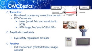
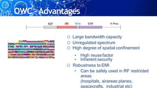
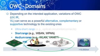
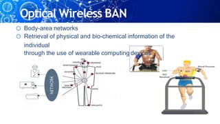
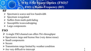
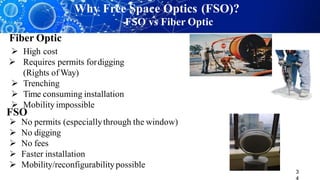
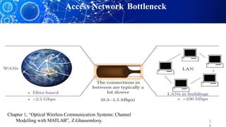
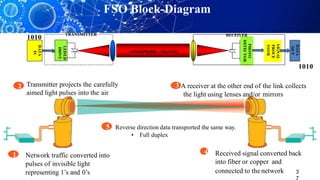
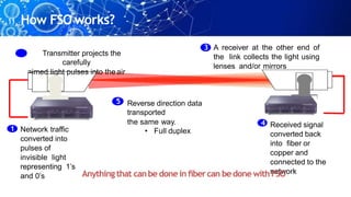
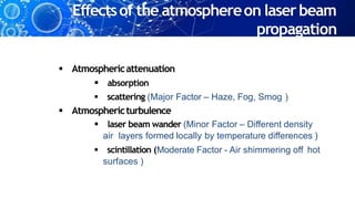
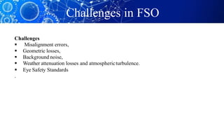
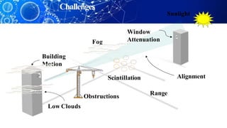
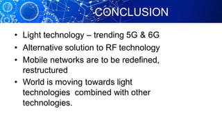
OUTLINE
• Introduction
• What is FSO
• Why FSO?
• Basics of FSO
• Challenges
• Applications
• Opportunities
• Conclusion
September 11,2001,New York
Every thing was destroyed including
normal
fiber link
Wall street stock
market was closed
because the
communication
was destroyed
Two of these units were used between
building to re-establish a high speed
communication link.
OlympicTV Using Free-SpaceOpticalDataLink
• SYDNEY, Australia, Sept. 18 -- Television signals of the Olympic Games broadcast
over a free- space optical link -TeraBeam Networks, a Seattle-based fiberless
broadband IP services provider.
• Until now, worldwide broadcast networks have used fiber optics or microwave systems to
transmit television signals.
• Lucent Technologies - eight broadcast channels between the International Broadcast
Centre and Sydney's Olympic Aquatics Centre over a free-space optical data link.
• Separate signals for the UK (BBC), Canada, Japan, Mexico and Germany
broadcasting teams, along with NBC, are being sent over a single low-powered light
beam, said TeraBeam Networks.
• We're thrilled to be helping some of the world's Olympics broadcasters, said Dan
Hesse, president and CEO of TeraBeam.
• This is a very real way to show that fiberless optics is not just a promise for the future, but
a reality now.
FSO INSTALLATIONS
History of Free Space
Optics
• The transmission of information using light
is actually not a new idea.
Great
Wall
Origin
• Firstly usedby Greeksin 8th century.
• Accordingto them fireasthe light source,the
atmosphere as transmission medium and an
eyeasa receiver.
• 19th century,AlexanderGrahamBell – done
experiments - which were later called as
Photophone.
In the late nineteenth century, Alexander Bell
expanded his "phone-phone" communication
which modulated by sunlight.
Origin
(cont.)
• Bel converted voice soundsinto telephone signals
and transmitted them between receivers through
free spacealong abeamof light for a distance of
some600feet.
• But Photophone never becamecommercial
reality.
• Though it demonstrated the basicprincipleof
optical transmissions.
History of FSO Communications
 Has been used for thousandsof years in various forms
 Around 800 BC, ancients Greeks and Romans used fire beacons for signaling
In 1880 Alexander Graham Bell created the Photophone by modulating the sun
radiation with voice signal
German troops used Heliograph telegraphy transmitters to send optical Morse
signals for distances of up to 4 km at daylight (up to 8 km at night) during the 1904/05
 The invention of lasers in the 1960srevolutionized FSO communications
Transmission of television signal over a 30-mile using GaAs LED by researchers
working in the MIT Lincolns Laboratoryin 1962
The first laser link to handle commercial traffic was built in Japan by Nippon
Electric Company (NEC) around 1970
Introduction
• Light becomes an intelligent Language.
• What drives me on this topic? New ideas improve
life
• Emerging technology trends – IoT with
Optical wireless
Introduction
• Today’s Internet of Things (IoT), covering any
communication between devices, is narrowband
and not always provides reliability and low
latency at the same time.
• A wide range of future IoT applications, i.e.
flexible manufacturing, augmented reality and
autonomous cars, will use artificial intelligence
in the cloud to process sensor data jointly in
real time.
Introduction
• This future IoT will need mobile communication
providing high bandwidth, reliable connectivity and low
latency at the same time.
• While radio spectrum is densely populated, light
communication (LC) can use unlicensed optical
spectrum and enable high data rates over short
distances for future IoT.
• By networking multiple LC-enabled access points,
one can build a new mobile communication system
integrated with lighting infrastructure that enables the
future IoT.
Introduction
• The main challenge to approach futureIoT is to
develop OWC further into the mass-market
serving a greater variety of use cases than today.
• OWC needs an open architecture, consensus
building towards standards, a roadmap to support
future IoT and technology demonstrations in real
environments, such as indoors, manufacturing,
logistics, conference rooms and outdoors for fixed-
wireless access.
Introduction
• Wireless communication goes optical.
• The ability to steer light beams effectively to
IoT devices solves the key challenges that
radio based communication is now struggling
with.
According to the Internet Society, over
80% of the world will be connected to the
Internet by2020.
Mobile and application services are the
future of the Internet.
 3G: 2Mb/s
 4G: designed for 1Gb/s
4G speed inATT and Verizon is 10 Mb/s
Demand for High-speed
Communications
OpticalWirelessCommunications(OWC)
o OWC: Wireless (unguided) transmission through the
deploymentof
optical frequencies
• Infrared (IR)
• Visible (VL)
• Ultraviolet (UV)
OWC History
o The use of sunlight
• Heliograph (Information delivery
using mirror reflection of
sunlight)
o The use of fire or lamp
• Beacon fire
• Lighthouse
• Signal lamp for ship-to-ship
communication
OWC Basics
o Transmitter
• Baseband processing in electrical domain
• E/O Conversion
 Laser (small FoV and restricted to
LOS)
 LED (large FoV and LOS/NLOS)
o Amplitude constraints
• Eye-safety regulations for laser
o Receiver
• O/E Conversion (Photodetector, Image
sensor)
o Large bandwidth capacity
o Unregulated spectrum
o High degree of spatial confinement
• High reusefactor
• Inherent security
o Robustness to EMI
• Can be safely used in RF restricted
areas
(hospitals, airareas planes,
spacecrafts, industrial etc)
OWC -Advantages
OWC Gbit/s UseCases
IoT: Flexible
Manufacturing
IoT:
Car2Car,
Car2Infra
Secure
Wireless
Augmented reality,
hospitals, support
for disabled people
In-flight
Entertainmen
t
Mass
transportation
Conference
Rooms
Private
Households
Opt. Backhaul
for small cells
in 5G
Precise Indoor
Positioning
OWC -Domains
o Depending on the intended application, variations of OWC
(UV, IR,
VL) can serve as a powerful alternative, complementary or
supportive technology to the existing ones
• Ultra-short range (e.g., optical circuitinterconnects)
• Shortrange (e.g., WBAN, WPAN)
• Mediumrange (e.g., WLAN, VANET)
• Long range (e.g., inter-building connections)
• Ultra-longrange (e.g., satellite links)
~mm >10,000km
km
m
Optical Wireless BAN
o Body-area networks
o Retrieval of physical and bio-chemical information of the
individual
through the use of wearable computing devices
Optical Wireless PAN
o Personal area networks: “Last meter”
connectivity for interconnecting devices
centered around an individual
person's workspace
• Giga-IR ~ 1.25 Gb/s (limited
mobility)
• 10Gb/s IR under development
• IEEE 802.15.7:Enhanced mobility but limited data
rate
o Smartphone communicationusing visiblelight(phone-to-
phone,
phone-to-TV, phone-to-vending machine, phone-to-POS
Optical Wireless LAN
OpticalWireless
o In line with governmental plans worldwide to
phase out incandescent bulbs and fluorescent
lights, it is predicted that LEDs will be the
ultimate light source in the near future.
o Visible light communications (VLC) a.k.a Li-Fi
• Dual use of lightning for illumination and communication
o Start-up companies on
VLC
• PureVLC (UK)
• OLEDCOMM
(France)
• Visilink (Japan)
Optical Wireless Underwater
o Typical choice for
underwater
transmission is acoustic

kbps @ km’s
o Complimentary to long
range
underwater acoustic
systems
o Visible light band (380 nm
Optical Wireless VANET
o Vehicle-to-vehicle communication (V2V)
o Vehicle-to-infrastructure communication
(V2I)
o Aircraft-to-aircraft
o Aircraft-to-ground
o Aircraft-to-
satellite
o Aircraft-to-HAP
o Drones
Optical Wireless for Airborne
Corner Cube
reflector
Ground station @ 4km
OWC terminal
3
Why Free Space Optics (FSO)?
FSO vs Radio-Frequency (RF)
RF
 Spectrumis scarce and low bandwidth
 Spectrum isregulated
 Suffers from multi-pathfading
 Susceptible toeavesdropping
 Large components
FSO
 A single FSO channel can offers Tb/s throughput
 Spectrumis large and license free (very dense reuse)
 Small components
 Secure
 Transmission range limited by weather condition
 Are very difficult to intercept
3
 Mobility impossible
 No permits (especiallythrough the window)
 No digging
 No fees
 Faster installation
 Mobility/reconfigurabilitypossible
Fiber Optic
 High cost
 Requires permits fordigging
(Rights of Way)
 Trenching
 Time consuming installation
FSO
Why Free Space Optics (FSO)?
FSO vs Fiber Optic
Why
FSO?
• FSO Communication is using the LASER light as
the carrier.
• Full Duplex, Full Speed AND No Delay.
• Up to 1 Gbps Ethernet
• Distances – up to5km.
• No License is required.
• Easy to install and almost no maintenance is
required.
Chapter 1, “Optical Wireless Communication Systems: Channel
Modelling with MATLAB”, Z.Ghassemlooy. 3
Access Network Bottleneck
3
1010
1010
DATA
IN
LED/LD
DRIVE
R
PHOTO
DETECTOR
S
IGNAL
PROCE
SSOR
DATA
OUT
ATMOSPHERIC CHANNEL
TRANSMITTER RECEIVER
FSO Block-Diagram
1 Network traffic converted into
pulses of invisible light
representing 1’s and 0’s
2 Transmitter projects the carefully
aimed light pulses into the air
5 Reverse direction data transported the same way.
• Full duplex
3 A receiver at the other end of the link collects
the light using lenses and/or mirrors
4 Received signal converted back
into fiber or copper and
connected to the network
11 How FSO works?
2 Transmitter projects the
carefully
aimed light pulses into theair
5 Reverse direction data
transported
the same way.
• Full duplex
1 Network traffic
converted into
pulses of
invisible light
representing 1’s
and 0’s
3 A receiver at the other end of
the link collects the light using
lenses and/or mirrors
4 Received signal
converted back
into fiber or
copper and
connected to the
network
Anything that canbe donein fibercan bedone withFSO
Effectsof the atmosphereon laserbeam
propagation
 Atmosphericattenuation
 absorption
 scattering (Major Factor – Haze, Fog, Smog )
 Atmosphericturbulence
 laser beam wander (Minor Factor – Different density
air layers formed locally by temperature differences )
 scintillation (Moderate Factor - Air shimmering off hot
surfaces )
Challenges in FSO
Challenges
 Misalignment errors,
 Geometric losses,
 Background noise,
 Weather attenuation losses and atmosphericturbulence.
 Eye Safety Standards
.
Sunlight
Building
Motion
Alignment
Window
Attenuation
Fog
Scintillation
Range
Obstructions
Low Clouds
Challenges
How can this be achieved?
• Choice of the wavelength -1550 nm
• Wavelength division multiplexing (WDM)
for capacity increase
• Choice of optimum modulation format for
FSO- PolSK Choosen
• Relays for Link Distance Enhancement.
Channel Models
4
1. Log Normal-weak turbulence
2. Gamma-Gamma- Weak, Moderate
& Strong turbulence
3. Negative exponential –Strong turbulence
CONCLUSION
• Light technology – trending 5G & 6G
• Alternative solution to RF technology
• Mobile networks are to be redefined,
restructured
• World is moving towards light
technologies combined with other
technologies.
References
1. Ghassemlooy, Z., Popoola, W., Rajbhandari, S. Optical Wireless Communications: System and Channel Modelling with MATLAB, New
York: CRC Press,2013.
Khaligi,M.A., Uysal, M. (2014) Survey on free space optical communication: A communication theory perspective, IEEE
Communication. Surveys andTutorials, vol. 16, no. 4, pp. 2231-2258
K.Prabu et.al(2017) BER analysis of SS -WDM based FSO System for Vellore weather conditions, Optics Communications, Vol.403pp 73-
80.
Mahdy ,A., Deogun, A.G.S. (2004) . Wireless optical communications: a survey, Proceedings of the IEEE Wireless Communications and
Networking Conference (WCNC), Atlanta,GA ,pp. 2399–2404.
Prabu ,K., Kumar D.S., Srinivas, T .(2014) . Performance analysis of FSO links under strong atmospheric turbulence conditions using
various modulation schemes, Optik ,125 (19) 5573–5581.
Andrews., Larry,C., Ronald L. PHILLIPS. (2005) Laser beam propagation through random media, SPIE press, Vol. 1
Prabu ,K., Kumar, D.S.(2014) Bit error rate analysis of free-space optical system with spatial diversity over strong atmospheric turbulence
channel with pointing errors, Optical Engineering , 53 (12), 126108–12610.
Mitsuji Matsumoto, (2012). Next Generation Free-space Optical System by System Design Optimization and PerformanceEnhancement,
Proceedings of Progress in Electromagnetics Research Symposium,pp. 501-506.
Patnaik, B., Sahu, B.K. (2012) Novel QPSK Modulation for DWDM Free Space Optical Communication System, Wireless Advanced,
pp. 170-175
Aldouri1,M.Y., Mahdi,M., Jameel,L.W.(2016) FSO Optical System UtilizingDPSK Advance Modulation Technique , IJCSMC, Vol. 5
Popoola,W.O., Ghassemlooy,W., LEITGEB, E.(2016). Free-Space Optical Communication in Atmospheric Turbulence using DPSK
Subcarrier Modulation ,Research gate, vol. 27, pp. 228818724
Kamran Kiasaleh, (2005) .Performance of APD-Based, PPM free space optical communication systems in atmospheric turbulence, IEEE
2.
3.
4.
5.
6.
7.
8.
9.
10.
11.
12.
Transactions on Communications,vol. 53, pp.1455-1461. NITT
Thank
You!!
NIT

OWC NEW (1).pptx

  • 1.
    OUTLINE • Introduction • Whatis FSO • Why FSO? • Basics of FSO • Challenges • Applications • Opportunities • Conclusion
  • 2.
  • 3.
    Every thing wasdestroyed including normal fiber link Wall street stock market was closed because the communication was destroyed
  • 4.
    Two of theseunits were used between building to re-establish a high speed communication link.
  • 5.
    OlympicTV Using Free-SpaceOpticalDataLink •SYDNEY, Australia, Sept. 18 -- Television signals of the Olympic Games broadcast over a free- space optical link -TeraBeam Networks, a Seattle-based fiberless broadband IP services provider. • Until now, worldwide broadcast networks have used fiber optics or microwave systems to transmit television signals. • Lucent Technologies - eight broadcast channels between the International Broadcast Centre and Sydney's Olympic Aquatics Centre over a free-space optical data link. • Separate signals for the UK (BBC), Canada, Japan, Mexico and Germany broadcasting teams, along with NBC, are being sent over a single low-powered light beam, said TeraBeam Networks. • We're thrilled to be helping some of the world's Olympics broadcasters, said Dan Hesse, president and CEO of TeraBeam. • This is a very real way to show that fiberless optics is not just a promise for the future, but a reality now.
  • 6.
  • 7.
    History of FreeSpace Optics • The transmission of information using light is actually not a new idea. Great Wall
  • 8.
    Origin • Firstly usedbyGreeksin 8th century. • Accordingto them fireasthe light source,the atmosphere as transmission medium and an eyeasa receiver. • 19th century,AlexanderGrahamBell – done experiments - which were later called as Photophone.
  • 9.
    In the latenineteenth century, Alexander Bell expanded his "phone-phone" communication which modulated by sunlight.
  • 10.
    Origin (cont.) • Bel convertedvoice soundsinto telephone signals and transmitted them between receivers through free spacealong abeamof light for a distance of some600feet. • But Photophone never becamecommercial reality. • Though it demonstrated the basicprincipleof optical transmissions.
  • 11.
    History of FSOCommunications  Has been used for thousandsof years in various forms  Around 800 BC, ancients Greeks and Romans used fire beacons for signaling In 1880 Alexander Graham Bell created the Photophone by modulating the sun radiation with voice signal German troops used Heliograph telegraphy transmitters to send optical Morse signals for distances of up to 4 km at daylight (up to 8 km at night) during the 1904/05  The invention of lasers in the 1960srevolutionized FSO communications Transmission of television signal over a 30-mile using GaAs LED by researchers working in the MIT Lincolns Laboratoryin 1962 The first laser link to handle commercial traffic was built in Japan by Nippon Electric Company (NEC) around 1970
  • 12.
    Introduction • Light becomesan intelligent Language. • What drives me on this topic? New ideas improve life • Emerging technology trends – IoT with Optical wireless
  • 13.
    Introduction • Today’s Internetof Things (IoT), covering any communication between devices, is narrowband and not always provides reliability and low latency at the same time. • A wide range of future IoT applications, i.e. flexible manufacturing, augmented reality and autonomous cars, will use artificial intelligence in the cloud to process sensor data jointly in real time.
  • 14.
    Introduction • This futureIoT will need mobile communication providing high bandwidth, reliable connectivity and low latency at the same time. • While radio spectrum is densely populated, light communication (LC) can use unlicensed optical spectrum and enable high data rates over short distances for future IoT. • By networking multiple LC-enabled access points, one can build a new mobile communication system integrated with lighting infrastructure that enables the future IoT.
  • 15.
    Introduction • The mainchallenge to approach futureIoT is to develop OWC further into the mass-market serving a greater variety of use cases than today. • OWC needs an open architecture, consensus building towards standards, a roadmap to support future IoT and technology demonstrations in real environments, such as indoors, manufacturing, logistics, conference rooms and outdoors for fixed- wireless access.
  • 16.
    Introduction • Wireless communicationgoes optical. • The ability to steer light beams effectively to IoT devices solves the key challenges that radio based communication is now struggling with.
  • 17.
    According to theInternet Society, over 80% of the world will be connected to the Internet by2020. Mobile and application services are the future of the Internet.  3G: 2Mb/s  4G: designed for 1Gb/s 4G speed inATT and Verizon is 10 Mb/s Demand for High-speed Communications
  • 18.
    OpticalWirelessCommunications(OWC) o OWC: Wireless(unguided) transmission through the deploymentof optical frequencies • Infrared (IR) • Visible (VL) • Ultraviolet (UV)
  • 19.
    OWC History o Theuse of sunlight • Heliograph (Information delivery using mirror reflection of sunlight) o The use of fire or lamp • Beacon fire • Lighthouse • Signal lamp for ship-to-ship communication
  • 20.
    OWC Basics o Transmitter •Baseband processing in electrical domain • E/O Conversion  Laser (small FoV and restricted to LOS)  LED (large FoV and LOS/NLOS) o Amplitude constraints • Eye-safety regulations for laser o Receiver • O/E Conversion (Photodetector, Image sensor)
  • 21.
    o Large bandwidthcapacity o Unregulated spectrum o High degree of spatial confinement • High reusefactor • Inherent security o Robustness to EMI • Can be safely used in RF restricted areas (hospitals, airareas planes, spacecrafts, industrial etc) OWC -Advantages
  • 22.
    OWC Gbit/s UseCases IoT:Flexible Manufacturing IoT: Car2Car, Car2Infra Secure Wireless Augmented reality, hospitals, support for disabled people In-flight Entertainmen t Mass transportation Conference Rooms Private Households Opt. Backhaul for small cells in 5G Precise Indoor Positioning
  • 23.
    OWC -Domains o Dependingon the intended application, variations of OWC (UV, IR, VL) can serve as a powerful alternative, complementary or supportive technology to the existing ones • Ultra-short range (e.g., optical circuitinterconnects) • Shortrange (e.g., WBAN, WPAN) • Mediumrange (e.g., WLAN, VANET) • Long range (e.g., inter-building connections) • Ultra-longrange (e.g., satellite links) ~mm >10,000km km m
  • 24.
    Optical Wireless BAN oBody-area networks o Retrieval of physical and bio-chemical information of the individual through the use of wearable computing devices
  • 25.
    Optical Wireless PAN oPersonal area networks: “Last meter” connectivity for interconnecting devices centered around an individual person's workspace • Giga-IR ~ 1.25 Gb/s (limited mobility) • 10Gb/s IR under development • IEEE 802.15.7:Enhanced mobility but limited data rate o Smartphone communicationusing visiblelight(phone-to- phone, phone-to-TV, phone-to-vending machine, phone-to-POS
  • 26.
    Optical Wireless LAN OpticalWireless oIn line with governmental plans worldwide to phase out incandescent bulbs and fluorescent lights, it is predicted that LEDs will be the ultimate light source in the near future. o Visible light communications (VLC) a.k.a Li-Fi • Dual use of lightning for illumination and communication o Start-up companies on VLC • PureVLC (UK) • OLEDCOMM (France) • Visilink (Japan)
  • 27.
    Optical Wireless Underwater oTypical choice for underwater transmission is acoustic  kbps @ km’s o Complimentary to long range underwater acoustic systems o Visible light band (380 nm
  • 28.
    Optical Wireless VANET oVehicle-to-vehicle communication (V2V) o Vehicle-to-infrastructure communication (V2I)
  • 29.
    o Aircraft-to-aircraft o Aircraft-to-ground oAircraft-to- satellite o Aircraft-to-HAP o Drones Optical Wireless for Airborne Corner Cube reflector Ground station @ 4km OWC terminal
  • 30.
    3 Why Free SpaceOptics (FSO)? FSO vs Radio-Frequency (RF) RF  Spectrumis scarce and low bandwidth  Spectrum isregulated  Suffers from multi-pathfading  Susceptible toeavesdropping  Large components FSO  A single FSO channel can offers Tb/s throughput  Spectrumis large and license free (very dense reuse)  Small components  Secure  Transmission range limited by weather condition  Are very difficult to intercept
  • 31.
    3  Mobility impossible No permits (especiallythrough the window)  No digging  No fees  Faster installation  Mobility/reconfigurabilitypossible Fiber Optic  High cost  Requires permits fordigging (Rights of Way)  Trenching  Time consuming installation FSO Why Free Space Optics (FSO)? FSO vs Fiber Optic
  • 32.
    Why FSO? • FSO Communicationis using the LASER light as the carrier. • Full Duplex, Full Speed AND No Delay. • Up to 1 Gbps Ethernet • Distances – up to5km. • No License is required. • Easy to install and almost no maintenance is required.
  • 33.
    Chapter 1, “OpticalWireless Communication Systems: Channel Modelling with MATLAB”, Z.Ghassemlooy. 3 Access Network Bottleneck
  • 34.
    3 1010 1010 DATA IN LED/LD DRIVE R PHOTO DETECTOR S IGNAL PROCE SSOR DATA OUT ATMOSPHERIC CHANNEL TRANSMITTER RECEIVER FSOBlock-Diagram 1 Network traffic converted into pulses of invisible light representing 1’s and 0’s 2 Transmitter projects the carefully aimed light pulses into the air 5 Reverse direction data transported the same way. • Full duplex 3 A receiver at the other end of the link collects the light using lenses and/or mirrors 4 Received signal converted back into fiber or copper and connected to the network
  • 35.
    11 How FSOworks? 2 Transmitter projects the carefully aimed light pulses into theair 5 Reverse direction data transported the same way. • Full duplex 1 Network traffic converted into pulses of invisible light representing 1’s and 0’s 3 A receiver at the other end of the link collects the light using lenses and/or mirrors 4 Received signal converted back into fiber or copper and connected to the network Anything that canbe donein fibercan bedone withFSO
  • 36.
    Effectsof the atmosphereonlaserbeam propagation  Atmosphericattenuation  absorption  scattering (Major Factor – Haze, Fog, Smog )  Atmosphericturbulence  laser beam wander (Minor Factor – Different density air layers formed locally by temperature differences )  scintillation (Moderate Factor - Air shimmering off hot surfaces )
  • 37.
    Challenges in FSO Challenges Misalignment errors,  Geometric losses,  Background noise,  Weather attenuation losses and atmosphericturbulence.  Eye Safety Standards .
  • 38.
  • 39.
    How can thisbe achieved? • Choice of the wavelength -1550 nm • Wavelength division multiplexing (WDM) for capacity increase • Choice of optimum modulation format for FSO- PolSK Choosen • Relays for Link Distance Enhancement.
  • 40.
    Channel Models 4 1. LogNormal-weak turbulence 2. Gamma-Gamma- Weak, Moderate & Strong turbulence 3. Negative exponential –Strong turbulence
  • 41.
    CONCLUSION • Light technology– trending 5G & 6G • Alternative solution to RF technology • Mobile networks are to be redefined, restructured • World is moving towards light technologies combined with other technologies.
  • 42.
    References 1. Ghassemlooy, Z.,Popoola, W., Rajbhandari, S. Optical Wireless Communications: System and Channel Modelling with MATLAB, New York: CRC Press,2013. Khaligi,M.A., Uysal, M. (2014) Survey on free space optical communication: A communication theory perspective, IEEE Communication. Surveys andTutorials, vol. 16, no. 4, pp. 2231-2258 K.Prabu et.al(2017) BER analysis of SS -WDM based FSO System for Vellore weather conditions, Optics Communications, Vol.403pp 73- 80. Mahdy ,A., Deogun, A.G.S. (2004) . Wireless optical communications: a survey, Proceedings of the IEEE Wireless Communications and Networking Conference (WCNC), Atlanta,GA ,pp. 2399–2404. Prabu ,K., Kumar D.S., Srinivas, T .(2014) . Performance analysis of FSO links under strong atmospheric turbulence conditions using various modulation schemes, Optik ,125 (19) 5573–5581. Andrews., Larry,C., Ronald L. PHILLIPS. (2005) Laser beam propagation through random media, SPIE press, Vol. 1 Prabu ,K., Kumar, D.S.(2014) Bit error rate analysis of free-space optical system with spatial diversity over strong atmospheric turbulence channel with pointing errors, Optical Engineering , 53 (12), 126108–12610. Mitsuji Matsumoto, (2012). Next Generation Free-space Optical System by System Design Optimization and PerformanceEnhancement, Proceedings of Progress in Electromagnetics Research Symposium,pp. 501-506. Patnaik, B., Sahu, B.K. (2012) Novel QPSK Modulation for DWDM Free Space Optical Communication System, Wireless Advanced, pp. 170-175 Aldouri1,M.Y., Mahdi,M., Jameel,L.W.(2016) FSO Optical System UtilizingDPSK Advance Modulation Technique , IJCSMC, Vol. 5 Popoola,W.O., Ghassemlooy,W., LEITGEB, E.(2016). Free-Space Optical Communication in Atmospheric Turbulence using DPSK Subcarrier Modulation ,Research gate, vol. 27, pp. 228818724 Kamran Kiasaleh, (2005) .Performance of APD-Based, PPM free space optical communication systems in atmospheric turbulence, IEEE 2. 3. 4. 5. 6. 7. 8. 9. 10. 11. 12. Transactions on Communications,vol. 53, pp.1455-1461. NITT
  • 43.