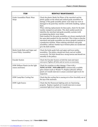
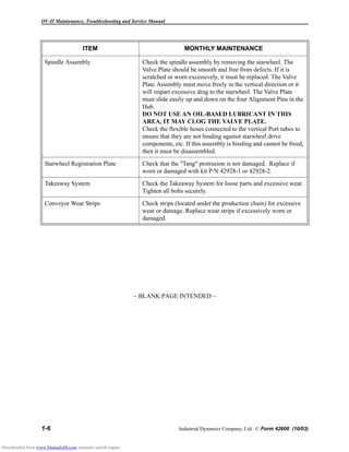
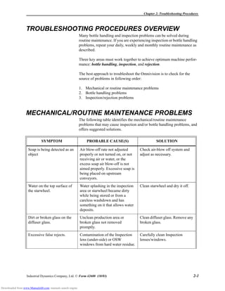
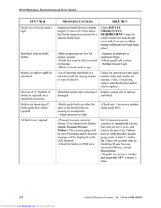
This document provides maintenance, troubleshooting and service information for the OV-II Empty Bottle Inspector system from Industrial Dynamics Company. It outlines the periodic maintenance procedures that should be followed, including daily, weekly and monthly tasks. Examples of daily maintenance include cleaning the diffuser glass and inspection head lenses. Weekly maintenance includes checking the vacuum system and lubricating parts. Monthly maintenance involves more thorough inspections, such as of the starwheels and guide assemblies. The document also provides troubleshooting guides and procedures for repairing or replacing various parts.

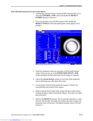
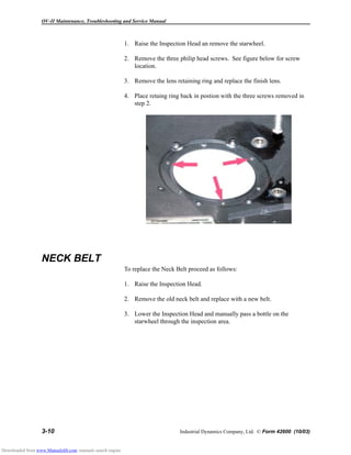
![Chapter 2: Troubleshooting Procedures
Industrial Dynamics Company, Ltd. © Form 42600 (10/03) 2-25
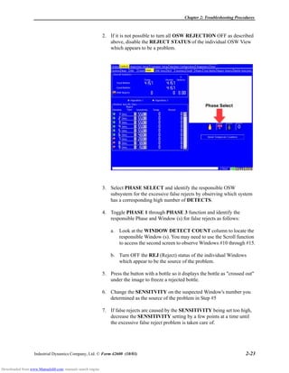
Rejecting No Bottles
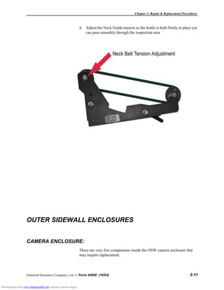
1. Check for and correct any maintenance-related or bottle handling
problems as discussed earlier in this chapter.
2. On CONTROL > SYSTEM screen, verify that each inspection
subsystem's REJECT STATUS function is ON.
SYMPTOM CHECK SOLUTION
The vacuum system has
failed or low vacuum (less
than 127 mm [5 inches
Hg]).
The vacuum warning gauge will
be out of tolerance and/or a red
error message will be displayed
on the monitor.
Ensure that circuit breaker CB1 is on,
the pressure/vacuum converter is
operational, and that the vacuum
gauge reading is within specification.
The camera lens aperture
and zoom servo positions
have lost calibration or
are not functioning,
causing an image which is
too bright, too dark, or
has the wrong zoom
setting.
The monitor display for one or
more of the zones will show up
as all dark, all white, or will have
an unusually small or unusually
large bottle image.
Verify the servo controller for that
camera is operating properly.
Recalibrate as required.
Excessive Rejects on one
inspection.
Check optical inspection
windows at the bottom of the
Inspection Head Base plate.
Clean the windows.
Check the OSW optical windows
inside the tunnel.
On the STATUS >
SYSTEM screen, the
DETECT COUNT for one
or more inspection systems
will have a high count.
Contaminants on diffuser disk or
OSW window.
OSW for fallen bottles.
1. Clean diffuser disk and window.
2. Clear the counters using the
CLEAR ALL CNT function.
3. Release the emergency stop
switch long enough to let 5 to 10
more bottles run through the
Omnivision. If all the bottles are
still rejected, then the problem is
not image related. Check RLD
inspection sensitivity. If no
bottles are rejected (this is what
should happen) allow bottles to
pass through the system.
Downloaded from www.Manualslib.com manuals search engine](https://image.slidesharecdn.com/ovii-230818232644-1bf48217/85/ovii-pdf-35-320.jpg)