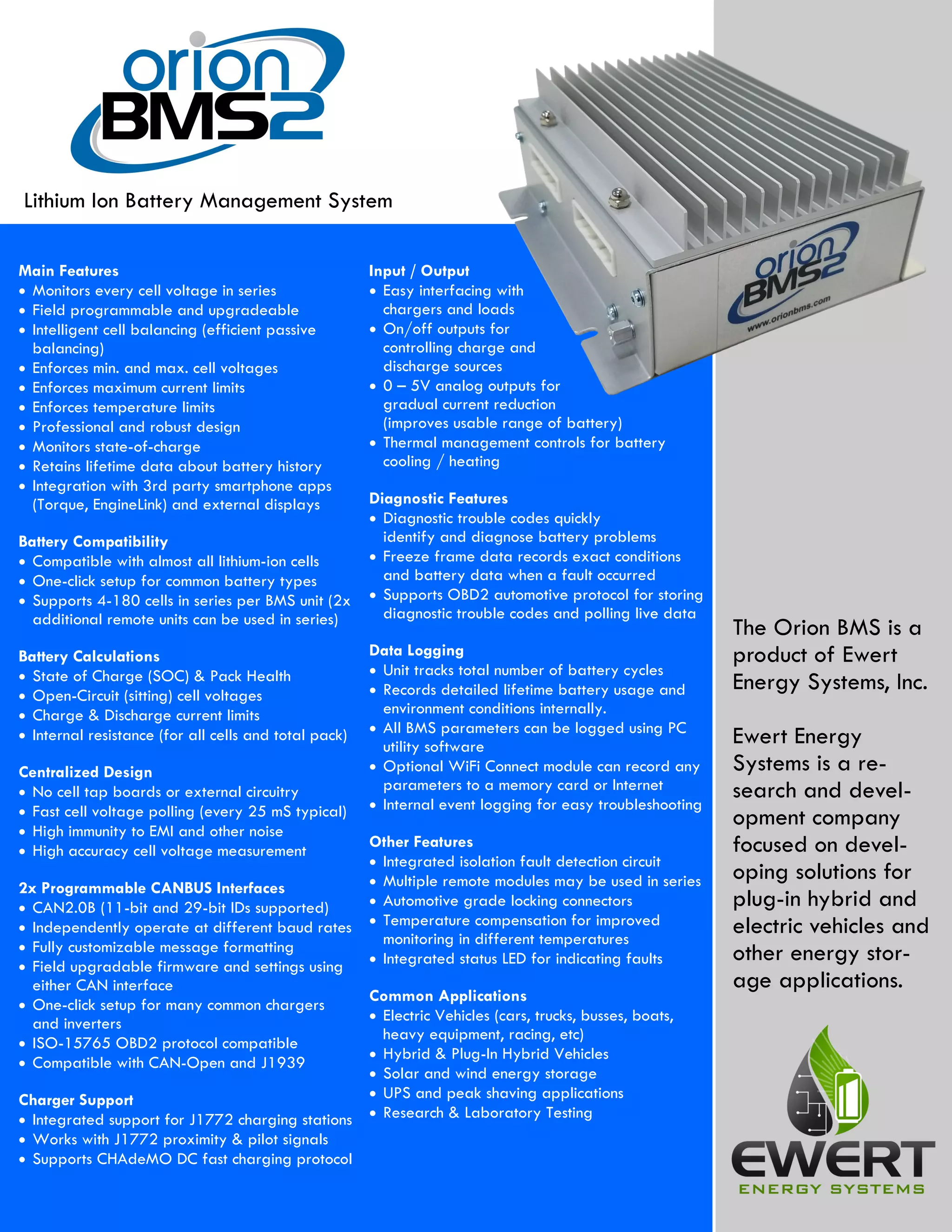
The Orion BMS is a
product of Ewert
Energy Systems, Inc.
Ewert Energy
Systems is a re-
search and devel-
opment company
focused on devel-
oping solutions for
plug-in hybrid and
electric vehicles and
other energy stor-
age applications.
Main Features
• Monitors every cell voltage in series
• Field programmable and upgradeable
• Intelligent cell balancing (efficient passive
balancing)
• Enforces min. and max. cell voltages
• Enforces maximum current limits
• Enforces temperature limits
• Professional and robust design
• Monitors state-of-charge
• Retains lifetime data about battery history
• Integration with 3rd party smartphone apps
(Torque, EngineLink) and external displays
Battery Compatibility
• Compatible with almost all lithium-ion cells
• One-click setup for common battery types
• Supports 4-180 cells in series per BMS unit (2x
additional remote units can be used in series)
Battery Calculations
• State of Charge (SOC) & Pack Health
• Open-Circuit (sitting) cell voltages
• Charge & Discharge current limits
• Internal resistance (for all cells and total pack)
Centralized Design
• No cell tap boards or external circuitry
• Fast cell voltage polling (every 25 mS typical)
• High immunity to EMI and other noise
• High accuracy cell voltage measurement
2x Programmable CANBUS Interfaces
• CAN2.0B (11-bit and 29-bit IDs supported)
• Independently operate at different baud rates
• Fully customizable message formatting
• Field upgradable firmware and settings using
either CAN interface
• One-click setup for many common chargers
and inverters
• ISO-15765 OBD2 protocol compatible
• Compatible with CAN-Open and J1939
Charger Support
• Integrated support for J1772 charging stations
• Works with J1772 proximity & pilot signals
• Supports CHAdeMO DC fast charging protocol
Input / Output
• Easy interfacing with
chargers and loads
• On/off outputs for
controlling charge and
discharge sources
• 0 – 5V analog outputs for
gradual current reduction
(improves usable range of battery)
• Thermal management controls for battery
cooling / heating
Diagnostic Features
• Diagnostic trouble codes quickly
identify and diagnose battery problems
• Freeze frame data records exact conditions
and battery data when a fault occurred
• Supports OBD2 automotive protocol for storing
diagnostic trouble codes and polling live data
Data Logging
• Unit tracks total number of battery cycles
• Records detailed lifetime battery usage and
environment conditions internally.
• All BMS parameters can be logged using PC
utility software
• Optional WiFi Connect module can record any
parameters to a memory card or Internet
• Internal event logging for easy troubleshooting
Other Features
• Integrated isolation fault detection circuit
• Multiple remote modules may be used in series
• Automotive grade locking connectors
• Temperature compensation for improved
monitoring in different temperatures
• Integrated status LED for indicating faults
Common Applications
• Electric Vehicles (cars, trucks, busses, boats,
heavy equipment, racing, etc)
• Hybrid & Plug-In Hybrid Vehicles
• Solar and wind energy storage
• UPS and peak shaving applications
• Research & Laboratory Testing
Lithium Ion Battery Management System
Cell Voltage Monitoring Specs
• Cell voltage measurement resolution of 0.1mV.
• Maximum individual cell voltage rating: 0.5v to 5v per cell tap.
• Cell voltage measurement total error <0.25% across full prod-
uct temperature range.
• Total pack voltages from 12vDC up to 800vDC (maximum).
• Supports from 4 to 340 cells per battery pack (requires remote
modules for more than 180 cells, 800vDC maximum).
Reliability & EMI Immunity
• Operates through the highest class passenger vehicle load
dump ISO 7637 Class IV (178V, 400mS, 0.5 ohm source.)
• Operates through ISO 7637 “cold crank” brownouts down to
5v on input supply rail and can operate > 100mS with no
power (with initial voltage of at least 12v)
• Meets EN 50498: 2010 EMC Aftermarket Vehicle Directive
• Meets European UNECE Reg 10.05 (Replaced Road Vehicle
Directive)
Product Dimensions & Weight (Typical, With Heatsink)
• 24-72 Cells: 7.15” (W) x 6.72” (L) x 2.37” (H) — 2.50 lbs
• 84-108 Cells: 9.50” (W) x 6.72” (L) x 2.37” (H) — 3.25 lbs
• 120-180 Cells: 15.52” (W) x 6.72” (L) x 2.37” (H) — 4.80 lbs
Isolation
• Cell taps isolated from input power supply, chassis and I/O
• 2.5kV isolation between each connector of cell taps
• Isolation allows for use of in-pack safety disconnects and fuses
• High voltage isolation fault detection circuit to monitor the
breakdown of wire insulation
I/O Interfaces
• 2 Digital signal outputs for enabling charge and discharge.
• 1 Digital signal output to control a battery charger
• 5 Digital programmable multi-purpose outputs
• 2 Digital programmable CANBUS (CAN2.0B) interfaces.
• 3 Analog 0-5v outputs that represent the following signals:
Charge / Discharge Current Limits and State of Charge (SOC)
• 1 PWM fan output and fan speed feedback monitor (external
switch and relay required, uses MPO4)
• 8 Thermistor inputs (Can support up to 800 thermistors through
external thermistor expansion modules (sold separately)
• 1 Dual range current sensor input (measures pack current)
Power Supply
• 3 redundant 12V—24V DC power supplies for reliability
• BMS retains data and settings without power
• Low power sleep mode
Specification Item Min Typ Max Units
Input Supply Voltage 8 30 Vdc
Supply Current—Active (at 25 degrees Celsius) < 2 Watts
Supply Current—Sleep (at 25 degrees Celsius, 12vDC) 450 µA
Operating Temperature -40 80 C
Sampling Rate for Current Sensor 8 mS
Sampling Rate for Cell Voltages 25 40 mS
Isolation Between Cell Tap #1 and Chassis / Input Supply 1.5 kVrms
Isolation Between Cell Taps #2+ and Chassis / Input Supply 2.5 kVrms
Isolation Between Cell Tap Connectors 2.5 kVrms
Digital Output Switching Voltage (Open Drain) 30 V
Digital Output Sink Continuous Current (Some outputs can
pulse up to 4A for contactors—see wiring manual for details)
175 mA
Cell Voltage Measurement Range 0.5 5 V
Cell Voltage Measurement Error (over 1-5v range) 0.25 %
Cell Balancing Current 200 mA
Cell Current (Operating) 0.5 mA
Cell Current (Low Power Sleep) 50 µA
Thermistor Accuracy 1 C
Cell Voltage Reporting Resolution 0.1 mV
Optional Specifications
CAN bus speed 125, 250, 500, or 1000 Kbps
Current Sensor Values +/- 200A, 500A, 800A, 1000A Available
161 E. Saint Charles Road
Carol Stream, IL 60188
Phone: (630) 868-3173
Fax: (866) 657-5667
www.orionbms.com
www.ewertenergy.com
Screenshot of Torque smartphone display
Screenshot of BMS utility

Orionbms2 specifications

  • 1.
    The Orion BMSis a product of Ewert Energy Systems, Inc. Ewert Energy Systems is a re- search and devel- opment company focused on devel- oping solutions for plug-in hybrid and electric vehicles and other energy stor- age applications. Main Features • Monitors every cell voltage in series • Field programmable and upgradeable • Intelligent cell balancing (efficient passive balancing) • Enforces min. and max. cell voltages • Enforces maximum current limits • Enforces temperature limits • Professional and robust design • Monitors state-of-charge • Retains lifetime data about battery history • Integration with 3rd party smartphone apps (Torque, EngineLink) and external displays Battery Compatibility • Compatible with almost all lithium-ion cells • One-click setup for common battery types • Supports 4-180 cells in series per BMS unit (2x additional remote units can be used in series) Battery Calculations • State of Charge (SOC) & Pack Health • Open-Circuit (sitting) cell voltages • Charge & Discharge current limits • Internal resistance (for all cells and total pack) Centralized Design • No cell tap boards or external circuitry • Fast cell voltage polling (every 25 mS typical) • High immunity to EMI and other noise • High accuracy cell voltage measurement 2x Programmable CANBUS Interfaces • CAN2.0B (11-bit and 29-bit IDs supported) • Independently operate at different baud rates • Fully customizable message formatting • Field upgradable firmware and settings using either CAN interface • One-click setup for many common chargers and inverters • ISO-15765 OBD2 protocol compatible • Compatible with CAN-Open and J1939 Charger Support • Integrated support for J1772 charging stations • Works with J1772 proximity & pilot signals • Supports CHAdeMO DC fast charging protocol Input / Output • Easy interfacing with chargers and loads • On/off outputs for controlling charge and discharge sources • 0 – 5V analog outputs for gradual current reduction (improves usable range of battery) • Thermal management controls for battery cooling / heating Diagnostic Features • Diagnostic trouble codes quickly identify and diagnose battery problems • Freeze frame data records exact conditions and battery data when a fault occurred • Supports OBD2 automotive protocol for storing diagnostic trouble codes and polling live data Data Logging • Unit tracks total number of battery cycles • Records detailed lifetime battery usage and environment conditions internally. • All BMS parameters can be logged using PC utility software • Optional WiFi Connect module can record any parameters to a memory card or Internet • Internal event logging for easy troubleshooting Other Features • Integrated isolation fault detection circuit • Multiple remote modules may be used in series • Automotive grade locking connectors • Temperature compensation for improved monitoring in different temperatures • Integrated status LED for indicating faults Common Applications • Electric Vehicles (cars, trucks, busses, boats, heavy equipment, racing, etc) • Hybrid & Plug-In Hybrid Vehicles • Solar and wind energy storage • UPS and peak shaving applications • Research & Laboratory Testing Lithium Ion Battery Management System
  • 2.
    Cell Voltage MonitoringSpecs • Cell voltage measurement resolution of 0.1mV. • Maximum individual cell voltage rating: 0.5v to 5v per cell tap. • Cell voltage measurement total error <0.25% across full prod- uct temperature range. • Total pack voltages from 12vDC up to 800vDC (maximum). • Supports from 4 to 340 cells per battery pack (requires remote modules for more than 180 cells, 800vDC maximum). Reliability & EMI Immunity • Operates through the highest class passenger vehicle load dump ISO 7637 Class IV (178V, 400mS, 0.5 ohm source.) • Operates through ISO 7637 “cold crank” brownouts down to 5v on input supply rail and can operate > 100mS with no power (with initial voltage of at least 12v) • Meets EN 50498: 2010 EMC Aftermarket Vehicle Directive • Meets European UNECE Reg 10.05 (Replaced Road Vehicle Directive) Product Dimensions & Weight (Typical, With Heatsink) • 24-72 Cells: 7.15” (W) x 6.72” (L) x 2.37” (H) — 2.50 lbs • 84-108 Cells: 9.50” (W) x 6.72” (L) x 2.37” (H) — 3.25 lbs • 120-180 Cells: 15.52” (W) x 6.72” (L) x 2.37” (H) — 4.80 lbs Isolation • Cell taps isolated from input power supply, chassis and I/O • 2.5kV isolation between each connector of cell taps • Isolation allows for use of in-pack safety disconnects and fuses • High voltage isolation fault detection circuit to monitor the breakdown of wire insulation I/O Interfaces • 2 Digital signal outputs for enabling charge and discharge. • 1 Digital signal output to control a battery charger • 5 Digital programmable multi-purpose outputs • 2 Digital programmable CANBUS (CAN2.0B) interfaces. • 3 Analog 0-5v outputs that represent the following signals: Charge / Discharge Current Limits and State of Charge (SOC) • 1 PWM fan output and fan speed feedback monitor (external switch and relay required, uses MPO4) • 8 Thermistor inputs (Can support up to 800 thermistors through external thermistor expansion modules (sold separately) • 1 Dual range current sensor input (measures pack current) Power Supply • 3 redundant 12V—24V DC power supplies for reliability • BMS retains data and settings without power • Low power sleep mode Specification Item Min Typ Max Units Input Supply Voltage 8 30 Vdc Supply Current—Active (at 25 degrees Celsius) < 2 Watts Supply Current—Sleep (at 25 degrees Celsius, 12vDC) 450 µA Operating Temperature -40 80 C Sampling Rate for Current Sensor 8 mS Sampling Rate for Cell Voltages 25 40 mS Isolation Between Cell Tap #1 and Chassis / Input Supply 1.5 kVrms Isolation Between Cell Taps #2+ and Chassis / Input Supply 2.5 kVrms Isolation Between Cell Tap Connectors 2.5 kVrms Digital Output Switching Voltage (Open Drain) 30 V Digital Output Sink Continuous Current (Some outputs can pulse up to 4A for contactors—see wiring manual for details) 175 mA Cell Voltage Measurement Range 0.5 5 V Cell Voltage Measurement Error (over 1-5v range) 0.25 % Cell Balancing Current 200 mA Cell Current (Operating) 0.5 mA Cell Current (Low Power Sleep) 50 µA Thermistor Accuracy 1 C Cell Voltage Reporting Resolution 0.1 mV Optional Specifications CAN bus speed 125, 250, 500, or 1000 Kbps Current Sensor Values +/- 200A, 500A, 800A, 1000A Available 161 E. Saint Charles Road Carol Stream, IL 60188 Phone: (630) 868-3173 Fax: (866) 657-5667 www.orionbms.com www.ewertenergy.com Screenshot of Torque smartphone display Screenshot of BMS utility