Download to read offline

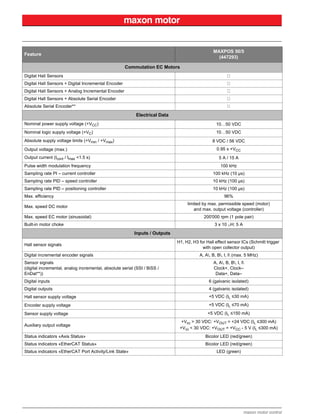

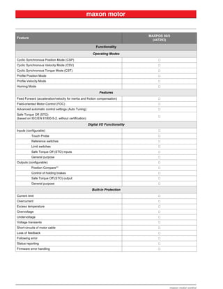


The MAXPOS is a motion controller capable of efficiently controlling DC motors and brushless motors. It provides high performance control features like field-oriented control for minimal torque ripple. It has various operating modes and communication interfaces, including EtherCAT, to meet industrial automation requirements. It is configured and controlled via EtherCAT or USB using graphical software.


![[YOUSUNG] Product Catalog](https://cdn.slidesharecdn.com/ss_thumbnails/yousungcatalog-180810042638-thumbnail.jpg?width=640&height=640&fit=bounds)


