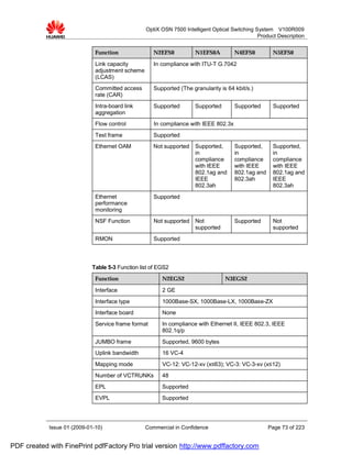
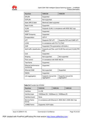
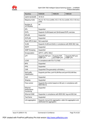
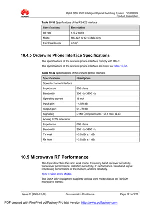
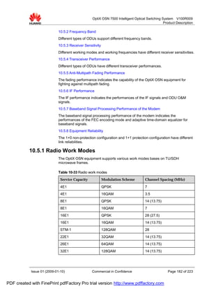
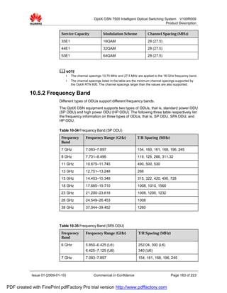
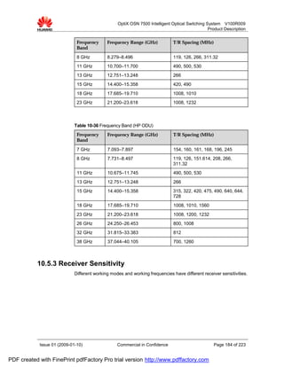
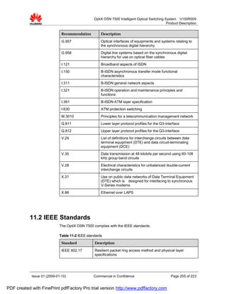
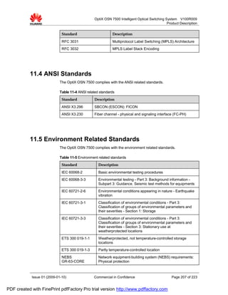
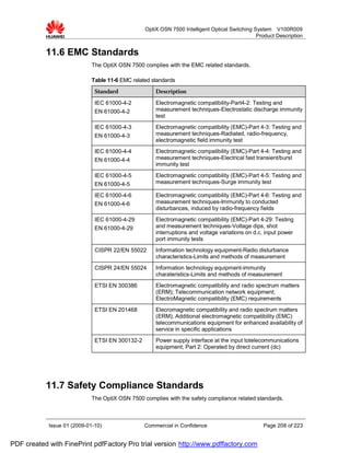
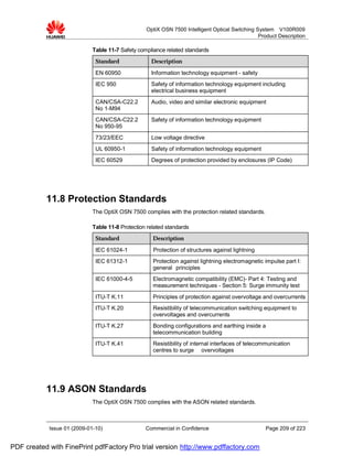
This document provides a product description of the OptiX OSN 7500 Intelligent Optical Switching System V100R009. It contains 13 chapters that describe the network application, functions, hardware, software architecture, data and ASON features, protection, operation and maintenance, security management, and technical specifications of the system. The document aims to give readers a comprehensive understanding of the system's capabilities and components. Some key points include its cross-connect and service capacities, board types, software structure, supported data services, ASON functionality, protection schemes, and OAM tools. Specification sections provide details on interfaces, timing, environmental requirements, and more.


![Glossaire du cablage_optique[1]](https://cdn.slidesharecdn.com/ss_thumbnails/glossaireducablageoptique1-121212033738-phpapp02-thumbnail.jpg?width=640&height=640&fit=bounds)
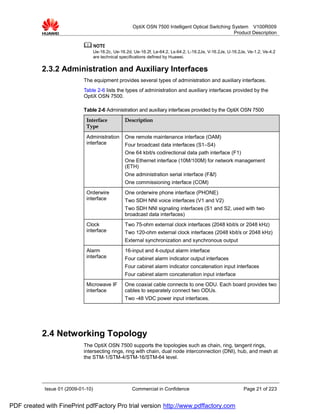
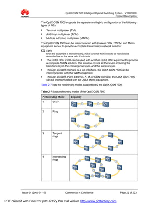
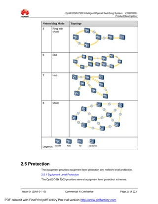
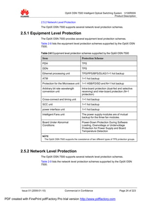
![Arm 4 canaux-logiques_2006-fva[1]](https://cdn.slidesharecdn.com/ss_thumbnails/arm-4canauxlogiques2006-fva1-141121043657-conversion-gate01-thumbnail.jpg?width=640&height=640&fit=bounds)


