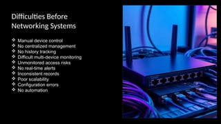
Difficulties Before
Networking Systems
Manual device control
No centralized management
No history tracking
Difficult multi-device monitoring
Unmonitored access risks
No real-time alerts
Inconsistent records
Poor scalability
Configuration errors
No automation
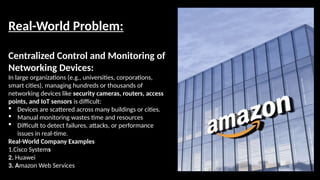
Real-World Problem:
Centralized Controland Monitoring of
Networking Devices:
In large organizations (e.g., universities, corporations,
smart cities), managing hundreds or thousands of
networking devices like security cameras, routers, access
points, and IoT sensors is difficult:
Devices are scattered across many buildings or cities.
Manual monitoring wastes time and resources
Difficult to detect failures, attacks, or performance
issues in real-time.
Real-World Company Examples
1.Cisco Systems
2. Huawei
3. Amazon Web Services
5.
Global E-Commerce andCloud
Networking:
Amazon:
Customer orders routing
Load balancing for web traffic
Inventory tracking across warehouses
Communication between servers
Google:
Connects data centers across the globe through private
fiber-optic networks
Internal networks for employee collaboration
6.
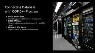
Connecting Database
with OOPC++ Program
Visual Studio 2022
Provides a powerful IDE for C++ development.
ODBC 17 Driver
Ensures reliable connection between C++ and SQL
Server.
Microsoft SQL Server
Offers a robust, scalable database system.
7.
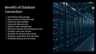
Benefits of Database
Connection:
Centralized data storage
Easy access to historical logs
Real-time data updates
Improved data security
Efficient data management
Reduces manual record-keeping errors
Enables multi-user access
Scalable for growing data needs
Supports automation and reporting
Simplifies backup and recovery
8.
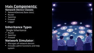
Main Components:
Network DeviceClasses:
NetworkDevices( Base class)
Router
Switches
Firewall
Logger
Inheritance Types
Single Inheritance
Router
Switches
Firewell
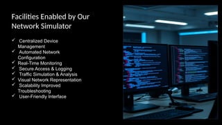
Network Simulator:
Manages all network devices
Includes admin functions and help
system
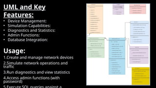
UML and Key
Features:
•Device Management:
• Simulation Capabilities:
• Diagnostics and Statistics:
• Admin Functions:
• Database Integration:
Usage:
1.Create and manage network devices
2.Simulate network operations and
traffic
3.Run diagnostics and view statistics
4.Access admin functions (with
password)
11.
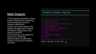
Main Outputs
1.The programprovides a menu-
driven interface for simulating
and managing enterprise
network operations.
2.Users can select options like
device management, network
simulation, diagnostics, and
viewing statistics.
3.The interface is designed for
ease of use, allowing
administrators to efficiently
monitor and control network
activities.
12.
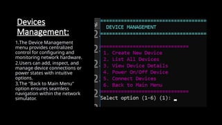
Devices
Management:
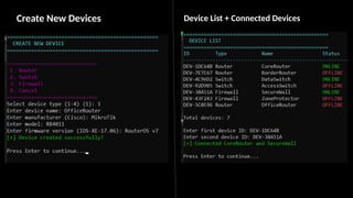
1.The Device Management
menuprovides centralized
control for configuring and
monitoring network hardware.
2.Users can add, inspect, and
manage device connections or
power states with intuitive
options.
3.The "Back to Main Menu"
option ensures seamless
navigation within the network
simulator.
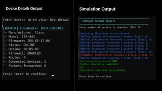
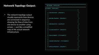
Network Topology Output:
•The network topology output
visually represents how devices
are connected in sequence,
showing the flow of data from
one device to another using
arrows — just like a simplified
map of the actual network
infrastructure.
16.
Connnection with
Database
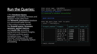
1 TheDatabase Query
Executor allows direct
interaction with
the Network_Simulators data
base using SQL commands.
2 It confirms successful
connections to the server ( .
SQLEXPRESS ) before accepting
queries.
3 Users can exit the tool by
typing 'exit', ensuring safe
termination of the session.
17.
Run the Queries:
1.TheDatabase Query
Executor successfully retrieves and
displays router data from
the Network_Simulators database
in a structured table format.
2.The output includes details
like firewall status, firmware
versions, packet metrics,
and router IDs, providing
comprehensive network insights.
3.The tool confirms query
completion (e.g., "7 row(s)
returned") and pauses for user
input, ensuring readability before
proceeding


![74676371-Coagulation-and-Flocculation[1].ppt](https://cdn.slidesharecdn.com/ss_thumbnails/74676371-coagulation-and-flocculation1-260116154109-a3cbf55e-thumbnail.jpg?width=640&height=640&fit=bounds)


