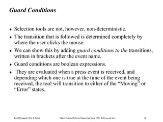
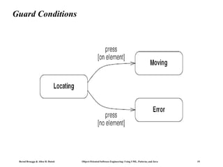
This document discusses state modeling and state diagrams in UML. It defines key concepts like events, states, transitions, and conditions. Events represent occurrences in time while states represent intervals of time between events. Transitions represent instantaneous changes between states. State diagrams are graphs that show the sequences of states and transitions caused by events. The document provides examples and notation for different types of events, states, activities, entry/exit activities, and guard conditions in state diagrams.
Welcome to my series of articles on Unified Modeling Language. This is "Session 9 – State Diagram" of the series.
Please view my other documents where I have covered each UML diagram with examples
This ppt covers the object modeling techniques. It has four topics: object model, dynamic model, functional model and the relationship between these models.
A tutorial on how to implement the State design pattern in Flex 3. We are going to have a traffic light move through several states (red, orange, green). Of course there are other states the traffic light might be in, as well as transitional states (green and orange at the same time), but lets keep things simple!
Q6. In a UML state machine diagram, 1. What is an event How is it re.pdfarshadkhan4488
Q6. In a UML state machine diagram, 1. What is an event? How is it represented? 2. What is a
guard/condition? How is it represented? 3. What is an action? How is it represented? 4. Make a
small state machine which shows all these being used. Yousides.CANuseexamplesfrom10points
An event is a change in the system (values of different variable can change). This means that the
state of the system before he event was different than the state of the system after the event. The
event is represented by a word or phrase on an arrow going from the current state to the next
state. One arrow/transition can have only one event. Same event can take use to different next
states depending on different guards. same event and same guards cannot take us to more than
one next state. Guard is a condition which has to be true in order for the event to take us from the
current state to the next state. It is represented as a Boolean expression (x==1,x!=5, etc.) within
square brackets. Multiple guards can be on a single transition. An action is an task which takes a
very small amount of time and can be performed during the transition. We also call it atomic i.e.,
very simple or instant. An action can also be performed immediately after entering a state or
immediately before leaving a state. If on a transition, an action is only performed after the event
occurs and the guard is true. An action is represented by placing a / before it. In the following
diagram, turn off, turn on, cardInserted etc are all events. readCard, eject card, shutdown are all
actions. We write failure as [failure == true] - this will convert the event failure into a guard..
A LITERATURE SURVEY OF COGNITIVE COMPLEXITY METRICS FOR STATECHART DIAGRAMSijseajournal
Statechart diagrams have inherent complexity which keeps increasing every time the diagrams are modified. This complexity poses problems in comprehending statechart diagrams. The study of cognitive complexity has over the years provided valuable information for the design of improved software systems. Researchers have proposed numerous metrics that have been used to measure and therefore control the complexity of software. However, there is inadequate literature related to cognitive complexity metrics that can apply to measure statechart diagrams. In this study, a literature survey of statechart diagrams is conducted to investigate if there are any gaps in the literature. Initially, a description of UML and statechart diagrams is presented, followed by the complexities associated with statechart diagrams and finally an analysis of existing cognitive complexity metrics and metrics related to statechart diagrams. Findings indicate that metrics that employ cognitive weights to measure statechart diagrams are lacking.
Chatty Kathy - UNC Bootcamp Final Project Presentation - Final Version - 5.23...John Andrews
SlideShare Description for "Chatty Kathy - UNC Bootcamp Final Project Presentation"
Title: Chatty Kathy: Enhancing Physical Activity Among Older Adults
Description:
Discover how Chatty Kathy, an innovative project developed at the UNC Bootcamp, aims to tackle the challenge of low physical activity among older adults. Our AI-driven solution uses peer interaction to boost and sustain exercise levels, significantly improving health outcomes. This presentation covers our problem statement, the rationale behind Chatty Kathy, synthetic data and persona creation, model performance metrics, a visual demonstration of the project, and potential future developments. Join us for an insightful Q&A session to explore the potential of this groundbreaking project.
Project Team: Jay Requarth, Jana Avery, John Andrews, Dr. Dick Davis II, Nee Buntoum, Nam Yeongjin & Mat Nicholas
Data Centers - Striving Within A Narrow Range - Research Report - MCG - May 2...pchutichetpong
M Capital Group (“MCG”) expects to see demand and the changing evolution of supply, facilitated through institutional investment rotation out of offices and into work from home (“WFH”), while the ever-expanding need for data storage as global internet usage expands, with experts predicting 5.3 billion users by 2023. These market factors will be underpinned by technological changes, such as progressing cloud services and edge sites, allowing the industry to see strong expected annual growth of 13% over the next 4 years.
Whilst competitive headwinds remain, represented through the recent second bankruptcy filing of Sungard, which blames “COVID-19 and other macroeconomic trends including delayed customer spending decisions, insourcing and reductions in IT spending, energy inflation and reduction in demand for certain services”, the industry has seen key adjustments, where MCG believes that engineering cost management and technological innovation will be paramount to success.
MCG reports that the more favorable market conditions expected over the next few years, helped by the winding down of pandemic restrictions and a hybrid working environment will be driving market momentum forward. The continuous injection of capital by alternative investment firms, as well as the growing infrastructural investment from cloud service providers and social media companies, whose revenues are expected to grow over 3.6x larger by value in 2026, will likely help propel center provision and innovation. These factors paint a promising picture for the industry players that offset rising input costs and adapt to new technologies.
According to M Capital Group: “Specifically, the long-term cost-saving opportunities available from the rise of remote managing will likely aid value growth for the industry. Through margin optimization and further availability of capital for reinvestment, strong players will maintain their competitive foothold, while weaker players exit the market to balance supply and demand.”
Adjusting primitives for graph : SHORT REPORT / NOTESSubhajit Sahu
Graph algorithms, like PageRank Compressed Sparse Row (CSR) is an adjacency-list based graph representation that is
Multiply with different modes (map)
1. Performance of sequential execution based vs OpenMP based vector multiply.
2. Comparing various launch configs for CUDA based vector multiply.
Sum with different storage types (reduce)
1. Performance of vector element sum using float vs bfloat16 as the storage type.
Sum with different modes (reduce)
1. Performance of sequential execution based vs OpenMP based vector element sum.
2. Performance of memcpy vs in-place based CUDA based vector element sum.
3. Comparing various launch configs for CUDA based vector element sum (memcpy).
4. Comparing various launch configs for CUDA based vector element sum (in-place).
Sum with in-place strategies of CUDA mode (reduce)
1. Comparing various launch configs for CUDA based vector element sum (in-place).
2. Bernd Bruegge & Allen H. Dutoit Object-Oriented Software Engineering: Using UML, Patterns, and Java 2
Overview:
Events
States
Transitions and Conditions
State Diagrams
State Diagram Behavior
3. Bernd Bruegge & Allen H. Dutoit Object-Oriented Software Engineering: Using UML, Patterns, and Java 3
Events
An event is an occurrence at a point in time, such as user
depresses left button or flight 123, departs from Chicago.
Events often correspond to verbs in the past tense (power
turned on, alarm set)
Events are messages sent to objects.
An event is an occurrence at a point in time, such as user
depresses left button to know various options. Another example
Rail departs from Mysore to Bangalore.
Events corresponds to verbs in the past tense or to the onset of
some condition. The time in which an event occurs is an
implicit attribute of the event.
4. Bernd Bruegge & Allen H. Dutoit Object-Oriented Software Engineering: Using UML, Patterns, and Java 4
Events
One event may logically precede or follow another or the two
events may be unrelated.
For example two flight can arrive at two different airports. Two
events are casually unrelated are said to be concurrent , they
have no effect on each other.
Events include error conditions and also normal occurrences.
Example timeout events , paper jammed in printer, transaction
aborted etc.,
There are several kinds of events
• Change event
• Signal event
• Time event
5. Bernd Bruegge & Allen H. Dutoit Object-Oriented Software Engineering: Using UML, Patterns, and Java 5
Signal Event
A signal is an explicit one-way transmission of information
from one object to another.
A signal event is the event of sending or receiving a signal.
Here we are more concerned about the receipt of a signal,
because it causes effects in the receiving object.
A signal is a message between objects while a signal event is
an occurrence in time.
Every signal transmission is a unique occurrence, but we group
them into signal classes and give each signal class a name to
indicate common structure and behavior.
6. Bernd Bruegge & Allen H. Dutoit Object-Oriented Software Engineering: Using UML, Patterns, and Java 6
Signal Event
Every signal transmission is a unique occurrence, but we group
them into signal classes and give each signal class a name to
indicate common structure and behavior.
Let us consider an example Kingfisher flight 123 departs from
Mysore on March 23, 2010 is an instance of signal class Flight-
Departure.
Some signals are simple occurrences, but most signal classes
have attributes indicating the values they convey.
The UML notation is the keyword signal in guillements(<< >>)
above the signal class in the top section of a box. The second
section lists the signal attributes.
7. Bernd Bruegge & Allen H. Dutoit Object-Oriented Software Engineering: Using UML, Patterns, and Java 7
Change Event
A change event is an event that is caused by the satisfaction of
a Boolean expression.
Event of the expression is continually tested – whenever the
expression changes from false to true , the event occurs.
The UML notation for change event is the keyword when
followed by a parenthesized Boolean expression.
Time Event
A time event is an event caused by the occurrence of an
absolute time or the elapse of a time interval.
The UML notation for an absolute time is the keyword when
followed by a parenthesized expression involving time. The
notation for a time interval is the keyword after followed by a
parenthesized expression that evaluates to a time duration.
8. Bernd Bruegge & Allen H. Dutoit Object-Oriented Software Engineering: Using UML, Patterns, and Java 8
States
A state is an abstraction of the values and links of an object. Set
of values and links are grouped together into a state according
to the gross behavior of objects.
UML notation for a state – a rounded box, containing an
optional state name.
The objects in a class have finite number of possible states.
Each object can only be in one state at a time. Objects pass
through one or more states during their lifetime.
A state specifies the response of an object to input events. All
events are ignored in a state, except those for which behavior is
explicitly prescribed. For example, if a digit is dialed in state
Dial tone, the phone line drops the dial tone and enters state
Dialing.
9. Bernd Bruegge & Allen H. Dutoit Object-Oriented Software Engineering: Using UML, Patterns, and Java 9
Event Vs. States
Events represent points in time. State represent intervals of
time. A state corresponds to the interval between two events
received by an object.
Both events and states depend on the level of abstraction. A
travel agent planning an itinerary would treat each segment of a
journey as a single event, an air traffic control system would
break each flight into many geographical legs.
10. Bernd Bruegge & Allen H. Dutoit Object-Oriented Software Engineering: Using UML, Patterns, and Java 10
Transitions and conditions
A transition is an instantaneous change from one state to
another. For example, when a phone is answered , the phone
line transitions from the Ringing state to the Connected state.
The choice of next state depends on both the original state and
the event received.
A guard condition is a Boolean expression that must be true in
order for a transition to occur.
A guard condition is checked only once, at the time the event
occurs and the transition fires, if the condition is true.
11. Bernd Bruegge & Allen H. Dutoit Object-Oriented Software Engineering: Using UML, Patterns, and Java 11
State diagrams
A state diagram is a graph whose nodes are states and whose
directed arcs are transitions between states.
A state diagram specifies the state sequences caused by events.
The state model consists of multiple state diagrams, one state
diagram for each class with important temporal behavior.
Sequences.
State names must be unique within the scope of a state
diagram.
12. Bernd Bruegge & Allen H. Dutoit Object-Oriented Software Engineering: Using UML, Patterns, and Java 12
One shot state diagram
The state model consists of multiple state diagrams, one state
diagram for each class with important temporal behavior.
One shot state diagrams represent objects with finite lives and
have initial and final states.
The initial state is entered on creation of an object, entry of the
final state implies destruction of the object.
13. Bernd Bruegge & Allen H. Dutoit Object-Oriented Software Engineering: Using UML, Patterns, and Java 13
Summary of Basic State Diagram Notation
State: Drawn as rounded box containing an optional name.
Transition: Drawn as a line from the origin state to the target
state.
Event: A signal event is shown as a label on a transition and
may be followed by parenthesized attributes.
14. Bernd Bruegge & Allen H. Dutoit Object-Oriented Software Engineering: Using UML, Patterns, and Java 14
State diagram behavior
An effect is a reference to a behavior that is executed in
response to an event.
An activity is the actual behavior that can be invoked by any
number of effects.
An activity may be performed upon a transition, upon the entry
to or exit from a state, or upon some other event within a state.
Activities can also represent internal control operations, a
program might increment an internal counter every time a
particular event occurs.
15. Bernd Bruegge & Allen H. Dutoit Object-Oriented Software Engineering: Using UML, Patterns, and Java 15
Activity effect
The notation for an activity is a slash(/) and the name (or
description) of the activity, followed the event that causes it.
The keyword do is reserved for indicating an ongoing activity
and may not be used as an event name.
16. Bernd Bruegge & Allen H. Dutoit Object-Oriented Software Engineering: Using UML, Patterns, and Java 16
Do-activities
A do-activity is an activity that continues for an extended time.
Do-activity can only occur within a state and cannot be
attached to a transition.
The notation “do /” denotes a do-activity that may be
performed for all or part of the duration that an object is in a
state.
17. Bernd Bruegge & Allen H. Dutoit Object-Oriented Software Engineering: Using UML, Patterns, and Java 17
Entry and exit activity
One can bind activities to entry or to exit from a state.
18. Bernd Bruegge & Allen H. Dutoit Object-Oriented Software Engineering: Using UML, Patterns, and Java 18
Guard Conditions
Selection tools are not, however, non-deterministic.
The transition that is followed is determined completely by
where the user clicks the mouse.
We can show this by adding guard conditions to the transitions,
written in brackets after the event name.
Guard conditions are boolean expressions.
They are evaluated when a press event is received, and
depending which one is true at the time of the event being
received, the tool will transition to either of the “Moving” or
“Error” states.
19. Bernd Bruegge & Allen H. Dutoit Object-Oriented Software Engineering: Using UML, Patterns, and Java 19
Guard Conditions