OOAD-unit-2 introduction to object orientation.ppt
1.
1
DEPARTMENT OF COMPUTERSCIENCE
AND ENGINEERING
(2016-17)
OBJECT ORIENTED ANALYSIS AND DESIGN
III B. Tech II Sem
UNIT-2
2.
What is classifier?
A classifier is a mechanism that describes structural
and behavioral features.
In general, the modeling elements that can have
instances are called classifiers.
Class, Instance, Data type, Signal, Component,
Node, Use case, Subsystem are classifiers.
(packages are not.)
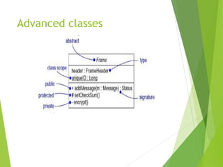
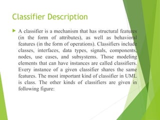
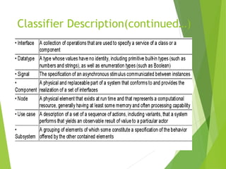
Classifier Description
Aclassifier is a mechanism that has structural features
(in the form of attributes), as well as behavioral
features (in the form of operations). Classifiers include
classes, interfaces, data types, signals, components,
nodes, use cases, and subsystems. Those modeling
elements that can have instances are called classifiers.
Every instance of a given classifier shares the same
features. The most important kind of classifier in UML
is class. The other kinds of classifiers are given in
following figure:
Special properties ofattributes and
operations
Visibility
Visibility
Public
Public[+]
[+]: any outside classifier with visibility to the given
classifier can use this feature.
Protected
Protected[#]:
[#]: any descendant of the classifier can use the
feature.
Private
Private[-]:
[-]: only the classifier itself can use the feature.
8.
Special properties ofattributes and
operations
Scope
Scope
The owner scope of a feature specifies whether the feature appears
in each instance of the classifier or whether there is just a single
instance of feature for all instances of the classifier.
instance : each instance holds its own value.
classifier : just one value for all instances. [static]
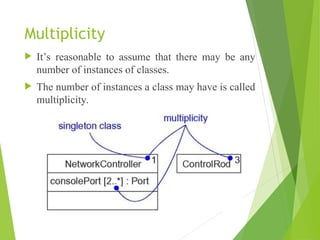
Multiplicity
It’s reasonableto assume that there may be any
number of instances of classes.
The number of instances a class may have is called
multiplicity.
11.
Attributes
The syntaxof an attribute in the UML is:
[ visibility ] name [ multiplicity ] [ : type ] [ = initial-value ]
[ { property- There are three defined properties
1. changeable : no restrictions on modifying the attribute’s
value
2. addOnly : additional value may be added for attributes with
a multiplicity > 1, but once created, a value may not be
removed or altered.
3. frozen : the attribute’s value may not be changed after
object is initialized. [const] string} ]
12.
Operations
The syntaxof an operation in UML is:
[ visibility ] name [ ( parameter-list ) ] [ : return-type ] [ { property-
string } ]
[ direction ] name : type [ = default-value ]
in, out, inout : means parameter may be modified or n
There are five defined properties
1. leaf : may not be overridden <page 7>
2. isQuery : leave the state of subsystem unchanged.
3. sequential : only one flow is in the object at a time.
4. guarded : sequential zing all calls.
5. concurrent : treating the operation as atomic.
3. 4. 5. are for concurrence.
13.
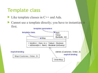
Template class
Liketemplate classes in C++ and Ada.
Cannot use a template directly; you have to instantiate it
first.
14.
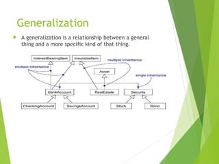
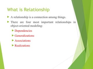
What is Relationship
A relationship is a connection among things.
There are four most important relationships in
object-oriented modeling:
Dependencies
Generalizations
Associations
Realizations
15.
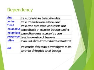
Dependency
Specifying achange in the specification of one thing
may affect another thing, but not necessarily the
reverse.
Rendering as a dashed line [ ]
UML defines a number of stereotypes.
There are eight stereotypes that apply to dependency
relationships among classes and objects in class
diagrams.
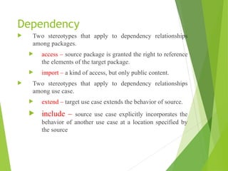
Dependency
Two stereotypesthat apply to dependency relationships
among packages.
access – source package is granted the right to reference
the elements of the target package.
import – a kind of access, but only public content.
Two stereotypes that apply to dependency relationships
among use case.
extend – target use case extends the behavior of source.
include – source use case explicitly incorporates the
behavior of another use case at a location specified by
the source
18.
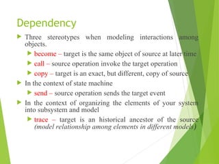
Dependency
Three stereotypeswhen modeling interactions among
objects.
become – target is the same object of source at later time
call – source operation invoke the target operation
copy – target is an exact, but different, copy of source
In the context of state machine
send – source operation sends the target event
In the context of organizing the elements of your system
into subsystem and model
trace – target is an historical ancestor of the source
(model relationship among elements in different models)
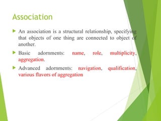
Association
An associationis a structural relationship, specifying
that objects of one thing are connected to object of
another.
Basic adornments: name, role, multiplicity,
aggregation.
Advanced adornments: navigation, qualification,
various flavors of aggregation
21.
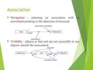
Association
Navigation :adorning an association with an
arrowhead pointing to the direction of traversal.
Visibility : objects at that end are not accessible to any
objects outside the association.
22.
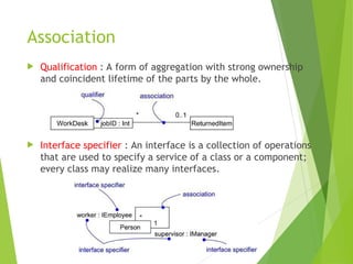
Association
Qualification :A form of aggregation with strong ownership
and coincident lifetime of the parts by the whole.
Interface specifier : An interface is a collection of operations
that are used to specify a service of a class or a component;
every class may realize many interfaces.
23.
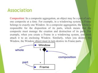
Association
Composition: In acomposite aggregation, an object may be a part of only
one composite at a time. For example, in a windowing system, a Frame
belongs to exactly one Window. In a composite aggregation, the whole is
responsible for the disposition of its parts, which means that the
composite must manage the creation and destruction of its parts. For
example, when you create a Frame in a windowing system, you must
attach it to an enclosing Window. Similarly, when you destroy the
Window, the Window object must in turn destroy its Frame parts.
24.
Association
Constraints
1.
1. implicit
implicit:The relationship is not manifest but, rather, is only
conceptual.
2.
2. ordered
ordered: the set of objects at one end of an association are in an explicit
order.
3.
3. changeable
changeable: links between objects may be changed.
4.
4. add Only
add Only: new links may be added from an object on the opposite end
of association.
5.
5. frozen
frozen: a link added may not be modified or deleted.
6.
6. Xor
Xor: over a set of associations, exactly one is man fest for each
associated object.
25.
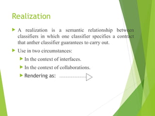
Realization
A realizationis a semantic relationship between
classifiers in which one classifier specifies a contract
that anther classifier guarantees to carry out.
Use in two circumstances:
In the context of interfaces.
In the context of collaborations.
Rendering as:
26.
Interfaces types andRoles
An interface is a collection of operations that are used to specify a
service of a class or a component. Graphically, an interface is rendered
(represented) as a circle; in its expanded form, an interface may be
rendered as a stereotyped class(a class with stereotype interface)
Two naming mechanism:
A simple name (only name of the interface).
A path name is the interface name prefixed by the name of the package
in which that interface lives represented.
27.
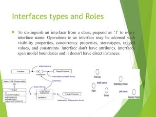
Interfaces types andRoles
To distinguish an interface from a class, prepend an ‘I’ to every
interface name. Operations in an interface may be adorned with
visibility properties, concurrency properties, stereotypes, tagged
values, and constraints. Interface don't have attributes. interfaces
span model boundaries and it doesn't have direct instances.
28.
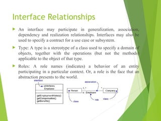
Interface Relationships
Aninterface may participate in generalization, association,
dependency and realization relationships. Interfaces may also be
used to specify a contract for a use case or subsystem.
Type: A type is a stereotype of a class used to specify a domain of
objects, together with the operations (but not the methods)
applicable to the object of that type.
Roles: A role names (indicates) a behavior of an entity
participating in a particular context. Or, a role is the face that an
abstraction presents to the world.
29.
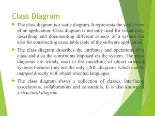
Class Diagram
Theclass diagram is a static diagram. It represents the static view
of an application. Class diagram is not only used for visualizing,
describing and documenting different aspects of a system but
also for constructing executable code of the software application.
The class diagram describes the attributes and operations of a
class and also the constraints imposed on the system. The class
diagrams are widely used in the modelling of object oriented
systems because they are the only UML diagrams which can be
mapped directly with object oriented languages.
The class diagram shows a collection of classes, interfaces,
associations, collaborations and constraints. It is also known as
a structural diagram.
30.
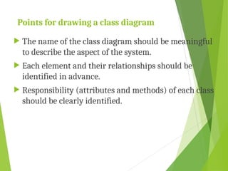
Points for drawinga class diagram
The name of the class diagram should be meaningful
to describe the aspect of the system.
Each element and their relationships should be
identified in advance.
Responsibility (attributes and methods) of each class
should be clearly identified.
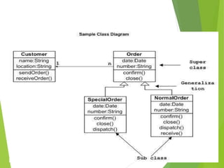
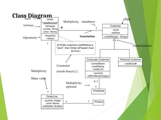
33.
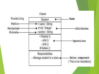
Class Diagram
Order
-dateReceived
-isPrepaid
-number :String
-price: Money
+dispatch()
+close()
Customer
-name
-address
+creditRating() : String()
Corporate Customer
-contactName
-creditRating
-creditLimit
+remind()
+billForMonth(Integer)
Personal Customer
-creditCard#
OrderLine
-quantity: Integer
-price: Money
-isSatisfied: Boolean
Product
* 1
1
*
Employee
*
{if Order.customer.creditRating is
"poor", then Order.isPrepaid must
be true }
* 1
Constraint
(inside braces{}}
Operations
Attributes
Name
Association
Multiplicity: mandatory
Multiplicity:
Many value
Multiplicity:
optional
Generalization
class
0..1
34.
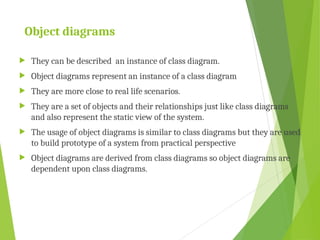
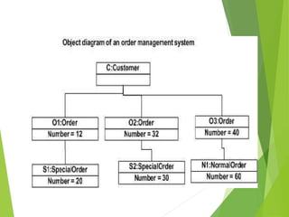
Object diagrams
Theycan be described an instance of class diagram.
Object diagrams represent an instance of a class diagram
They are more close to real life scenarios.
They are a set of objects and their relationships just like class diagrams
and also represent the static view of the system.
The usage of object diagrams is similar to class diagrams but they are used
to build prototype of a system from practical perspective
Object diagrams are derived from class diagrams so object diagrams are
dependent upon class diagrams.
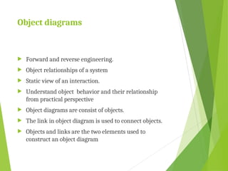
35.
Object diagrams
Forwardand reverse engineering.
Object relationships of a system
Static view of an interaction.
Understand object behavior and their relationship
from practical perspective
Object diagrams are consist of objects.
The link in object diagram is used to connect objects.
Objects and links are the two elements used to
construct an object diagram


![Special properties of attributes and
operations
Visibility
Visibility
Public
Public[+]
[+]: any outside classifier with visibility to the given
classifier can use this feature.
Protected
Protected[#]:
[#]: any descendant of the classifier can use the
feature.
Private
Private[-]:
[-]: only the classifier itself can use the feature.](https://image.slidesharecdn.com/ooad-unit-2-250922035401-57b8a15a/85/OOAD-unit-2-introduction-to-object-orientation-ppt-7-320.jpg)
![Special properties of attributes and
operations
Scope
Scope
The owner scope of a feature specifies whether the feature appears
in each instance of the classifier or whether there is just a single
instance of feature for all instances of the classifier.
instance : each instance holds its own value.
classifier : just one value for all instances. [static]](https://image.slidesharecdn.com/ooad-unit-2-250922035401-57b8a15a/85/OOAD-unit-2-introduction-to-object-orientation-ppt-8-320.jpg)
![Attributes
The syntax of an attribute in the UML is:
[ visibility ] name [ multiplicity ] [ : type ] [ = initial-value ]
[ { property- There are three defined properties
1. changeable : no restrictions on modifying the attribute’s
value
2. addOnly : additional value may be added for attributes with
a multiplicity > 1, but once created, a value may not be
removed or altered.
3. frozen : the attribute’s value may not be changed after
object is initialized. [const] string} ]](https://image.slidesharecdn.com/ooad-unit-2-250922035401-57b8a15a/85/OOAD-unit-2-introduction-to-object-orientation-ppt-11-320.jpg)
![Operations
The syntax of an operation in UML is:
[ visibility ] name [ ( parameter-list ) ] [ : return-type ] [ { property-
string } ]
[ direction ] name : type [ = default-value ]
in, out, inout : means parameter may be modified or n
There are five defined properties
1. leaf : may not be overridden <page 7>
2. isQuery : leave the state of subsystem unchanged.
3. sequential : only one flow is in the object at a time.
4. guarded : sequential zing all calls.
5. concurrent : treating the operation as atomic.
3. 4. 5. are for concurrence.](https://image.slidesharecdn.com/ooad-unit-2-250922035401-57b8a15a/85/OOAD-unit-2-introduction-to-object-orientation-ppt-12-320.jpg)
![Dependency
Specifying a change in the specification of one thing
may affect another thing, but not necessarily the
reverse.
Rendering as a dashed line [ ]
UML defines a number of stereotypes.
There are eight stereotypes that apply to dependency
relationships among classes and objects in class
diagrams.](https://image.slidesharecdn.com/ooad-unit-2-250922035401-57b8a15a/85/OOAD-unit-2-introduction-to-object-orientation-ppt-15-320.jpg)