Download as PDF, PPTX

![Bibliography
Bentley, I, Alcock, A, Murrain, P, McGlynn, S, Smith G (1985). Responsive environments. A manual for designers: Architectural Press, London. Available at http://www.amazon.co.uk/Responsive-Environments-Sue-Mc-
Glynn-ebook (Downloaded: 04 May 2016).
Biddulph, M. (2007). Introduction to residential layout. Routledge.
Bradbury, A., Cameron, A., Castell, B., Jones, P., Pharoah, T., Reid, S. and Young, A., (2007). Manual For Streets. UK: Thomas Telford Ltd./DfT. Carmona, M. (2010). Public places, urban spaces: the dimensions of urban
design. Routledge.
Cullen, G. (1961). The concise townscape. Routledge.
DCLG, 2015. Land value estimates for policy appraisal. London: Department for Communities and Local Government (DCLG), p.11. Available at: https://www.gov.uk/government/uploads/system/uploads/attachment_data/
file/407155/February_2015_Land_value_publication_FINAL.pdf (Accessed 01/05/16).
DETR, (2000). By Design. London: (Department of the Environment, Transport and the Regions), p.28.
Gehl, J. (2013). Cities for people. Island press.
Gehl, J. (2011). Life between buildings: using public space. Island Press.
Gibson, J. J. (1966). The senses considered as perceptual systems.
Google maps, (2016). Botley. [image] Available at: https://www.google.co.uk/maps/place/Botley,+Oxford/@51.7529301,-1.3032589,16.39z/data=!4m5!3m4!1s0x4876c661870d65c9:0x9bc2f53e680dee6c!8m2!3d51.750186
!4d-1.301084 (Accessed 04/05/16).
Jacobs, J. (1961). The death and life of great American cities. Vintage.
Lifetime Homes (2016) Lifetime Homes. [Online] Available at: http://www.lifetimehomes.org.uk/index.php (accessed 04/ 05/ 16).
Lucas, R., & Romice, O. (2008). Representing sensory experience in urban design. Design Principles and Practices: An International Journal, 2(4), 83-94.
Malnar, J. M. (2004). Sensory design. University of Minnesota Press.
Nasar, J. L. (1990). The evaluative image of the city. Journal of the American Planning Association, 56(1), 41-53.
Office for National Statistics (ONS) (2016) [ARCHIVED CONTENT] Ageing of the UK population - ONS. [Online] Available at: http://webarchive.nationalarchives.gov.uk/20160105160709/http://www.ons.gov.uk/ons/rel/
pop-estimate/population-estimates-for-uk--england-and-wales--scotland-and-northern-ireland/mid-2014/sty-ageing-of-the-uk-population.html (accessed 03/ 05/ 16).
Oxford.gov.uk (2015) Key facts about Vale of White Horse discrict. [Online] Available at: http://www.oxford.gov.uk/districtdata/download/downloads/id/130/vale_of_white_horse_key_facts_2015.pdf (accessed 05/ 05/ 16).
Proviser (2016) Vale of White Horse Average House Prices in 2015. [Online] Available at: http://www.proviser.com/regional/la_ua/vale_of_white_horse/house_price_explorer/average/2015 (accessed 06/ 05/ 16).
SBD (2016) Secure by Design Homes (1st edition). London: Secure by Design Available at: http://www.securedbydesign.com/wp-content/uploads/2016/03/Secured_by_Design_Homes_2016_V1.pdf (accessed 04/ 05/ 16).
Sheridan, T., & Van Lengen, K. (2003). Hearing architecture: Exploring and designing the aural environment. Journal of Architectural Education, 57(2), 37-44.
Vale of White Horse District Council (VWHDC), (2014). Vale Local Plan 2031. Wallingford.
Yeang, L. D. (2000). Urban design compendium. English Partnerships/Housing Corporation, London. Available at http://cfg.homesandcommunities.co.uk/urban-design-compendium?page_id=5542&page=202 (Downloaded
05/05/2015).
20](https://image.slidesharecdn.com/d913e9ea-a6c6-44ab-b588-73c9eabc7181-160607225914/85/OB_Studio2_Urban-Design1-20-320.jpg)
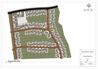
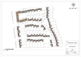
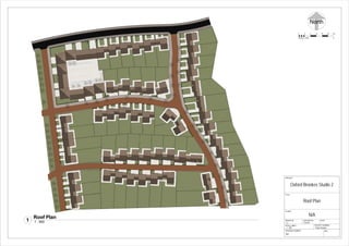
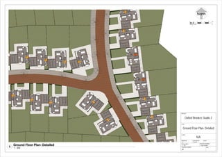

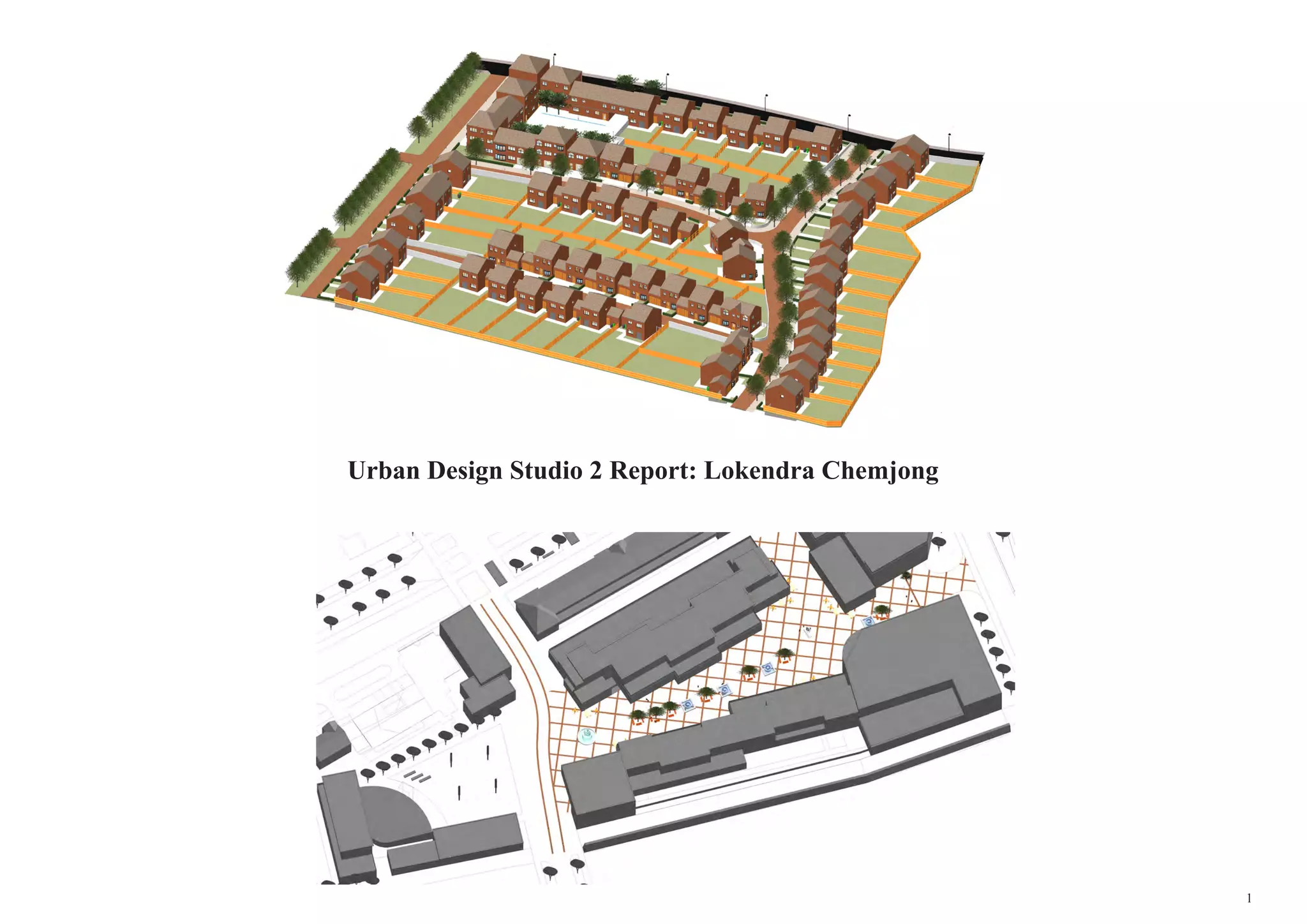
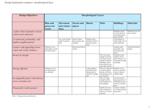
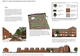
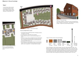
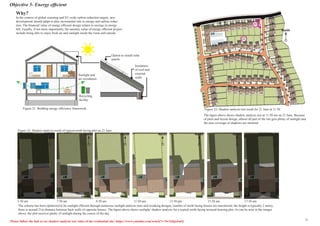
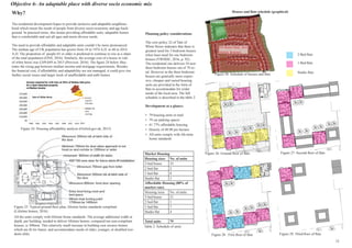
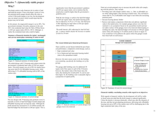
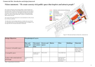
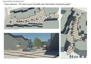
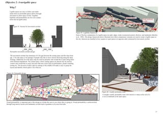
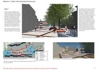
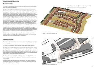
This document provides a design report for further developing residential and commercial sites from an initial urban design studio project. For the residential site, the objectives are to create a place that responds to the local context, is well-connected and permeable, has appealing townscape, is secure by design, is energy efficient, and provides an adaptable and socioeconomically diverse place to live. Various design elements are proposed to meet these objectives, including building character, street layout, planting, and housing types. For the commercial site, the objectives are to create a sensory rich public space and navigable space with a varied townscape. The report includes analysis, design proposals, and justification for the approaches.


