Downloaded 439 times


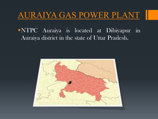
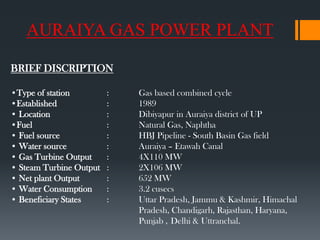
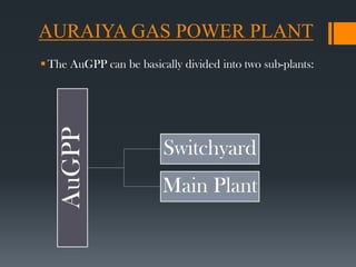

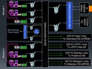
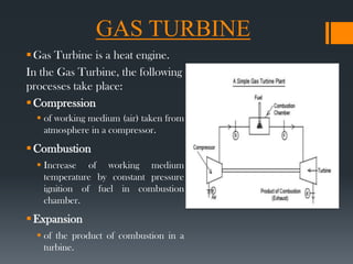

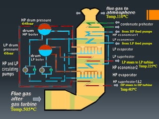
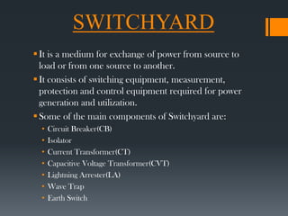
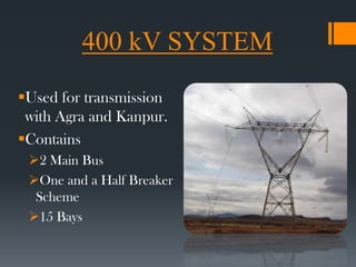

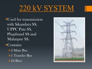


The document provides information about NTPC Auraiya Gas Power Plant (AuGPP) located in Uttar Pradesh, India. Some key details include: - AuGPP has a total installed capacity of 652 MW and uses natural gas and naphtha as fuel. - It uses a combined cycle with two gas turbine modules and two steam turbines to generate power more efficiently. - The plant's main components are gas turbines, steam turbines, waste heat recovery boilers, and generators. - Electricity is transmitted through a 220kV and 400kV switchyard to various states in northern India.


