SlideShare a Scribd company logo
1 of 7
Download to read offline
Approval Standard
       for
 Automatic Water
  Control Valves

                                  Class Number 1020


                                                 January 1976
                            m
                        e.co
                       as
                   gb
                  in
              in
             ra
        et
      .fir
  w
  w
 w


                                ©2002 FM Global Technologies LLC. All rights reserved.
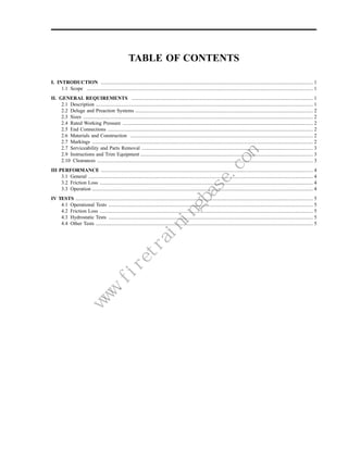
TABLE OF CONTENTS

I. INTRODUCTION ...................................................................................................................................................................... 1
     1.1 Scope ................................................................................................................................................................................. 1
II. GENERAL REQUIREMENTS .............................................................................................................................................. 1
     2.1 Description .......................................................................................................................................................................... 1
     2.2 Deluge and Preaction Systems ........................................................................................................................................... 2
     2.3 Sizes .................................................................................................................................................................................... 2
     2.4 Rated Working Pressure ..................................................................................................................................................... 2
     2.5 End Connections ................................................................................................................................................................. 2
     2.6 Materials and Construction ............................................................................................................................................... 2
     2.7 Markings ............................................................................................................................................................................. 2
     2.7 Serviceability and Parts Removal ...................................................................................................................................... 3
     2.9 Instructions and Trim Equipment ....................................................................................................................................... 3
     2.10 Clearances ......................................................................................................................................................................... 3
III PERFORMANCE ...................................................................................................................................................................... 4
     3.1 General ................................................................................................................................................................................ 4
     3.2 Friction Loss ....................................................................................................................................................................... 4
     3.3 Operation ............................................................................................................................................................................. 4
IV TESTS .......................................................................................................................................................................................... 5
    4.1 Operational Tests ................................................................................................................................................................ 5
    4.2 Friction Loss ....................................................................................................................................................................... 5
    4.3 Hydrostatic Tests ................................................................................................................................................................ 5
    4.4 Other Tests .......................................................................................................................................................................... 5
                                                              m
                                                          e.co
                                                         as
                                                     gb
                                                    in
                                                in
                                               ra
                                          et
                                        .fir
                                    w
                                    w
                                   w
January 1976                                                                                                 1020


I. INTRODUCTION

1.1 Scope

    1.1 Automatic water control valves are used to control the flow of water for various fire protection applications.
        They are normally used in special sprinkler systems such as deluge and preaction systems; but are also used
        to control the flow to water spray systems, foam making equipment and other special purpose systems.

    1.2 FM Approval is based on satisfactory evaluation of the product and the manufacturer in three major areas:
            – Examinations and tests on production samples are performed to evaluate (1) the suitability of the
              product, (2) the proper operation and performance of the product as specified by the manufacturer and
              required by FM Approvals, and (3) the durability and reliability of the product.
            – An examination of manufacturing facilities and quality control procedures is conducted to evaluate the
              manufacturer’s ability to produce the product which is examined and tested. These examinations are
              periodically repeated as part of FM Approvals’ product follow-up program.
            – Satisfactory field experience is the final test of Approval. Unsatisfactory field experience may neces-
              sitate withdrawal of FM Approval.

    1.3 The requirements of this standard are intended as guidelines reflecting current FM Approval tests and
        practices. Devices which do not precisely conform to these requirements may be Approved if they meet the
        intent of this standard. Similarly, items that do conform to these requirements may not be Approved if they
        do not meet the intent of these requirements or if other conditions govern.


II. GENERAL REQUIREMENTS

2.1 Description

    2.1.1 Automatic water control valves are generally single clapper valves with the clapper maintained on its seat
          (‘‘set’’ position) mechanically by a system of levers. All valves are released by some means which is
          external to the valve; usually a mechanical, hydraulic, pneumatic, electrical, or thermal actuating system
                                                 m
                                             e.co
                                            as
                                        gb
                                       in
                                   in
                                  ra
                             et
                           .fir


          or combination of these.
                       w
                       w
                      w


    2.1.2 Hydraulic type valves are maintained in the set position by system hydraulic pressure acting against a
          diaphragm connected to the mechanical members which actually hold the clapper closed. Releasing the
          pressure against the diaphragm trips the valve.

    2.1.3 Mechanical type valves are released from the set position by some mechanical means. This is often done
          by the action of a released weight or by the activations or deactivations of an electrical device such as a
          solenoid.

    2.1.4 Thermal type valves are released by heat from the fire acting on the valve itself. This valve utilizes a
          thermal device, such as a sprinkler-type link and lever arrangement or glass bulb, to hold the valve closed.
          Fusing the thermal device releases the valve clapper.


                                                                                           FM APPROVALS             1
1020                                                                                                   January 1976


2.2 Deluge and Preaction Systems

    Automatic water control valves are often used in deluge and preaction systems. Valves used for these applica-
    tions must meet the requirements of this standard; but more importantly, the deluge or preaction system itself
    must meet the requirements of Approval Standard Class 1011-1012 (Deluge Systems and Preaction Systems).


2.3 Sizes

    Recognized standard sizes for water control valves are 1, 11⁄2, 2, 21⁄2, 3, 4 and 6 in. (25.4, 38.1, 50.8, 63.5, 76.2,
    101.6 and 152.4). Other sizes may be approved, if they meet requirements and intent of this standard.


2.4 Rated Working Pressure

    Water control valves shall be designed for a rated working pressure of 175 psi (1206.6 kPa) or greater.


2.5 End Connections

    2.5.1 Valve bodies of 3 in. (76.2 mm) and larger sizes shall have flanged ends conforming to a recognized
          national standard for flanged fittings, such as ANSI B16.5. Smaller valves may have flanged ends or
          threaded ends conforming to a recognized national standard for tapered pipe thread, such as ANSI B2.1.
          Other end connections may be approved if there is a demonstrated need for them, and these will be
          examined on a case-by-case basis.

    2.5.2 Valves manufactured or for use outside North America may be approved with end connections conforming
          to national standards recognized in the country involved.


2.6 Materials and Construction

    2.6.1 All materials used in water control valves shall be suitable for the intended purpose. Valve parts which
          could affect the operation of the valve if they became corroded or tuberculated shall be constructed of
          corrosion resistant materials. This includes such parts as hinge pin bushings and clapper arm bushings.
          Metal seat rings which come in contact with rubber seating surfaces shall be constructed of materials
          which will not naturally adhere to rubber.

    2.6.2 All valve and release components shall be able to withstand the normal conditions of vibrations and
                                                             m
                                                         e.co
                                                        as
                                                    gb
                                                   in
                                               in
                                              ra
                                         et
                                       .fir


          atmospheres associated with manufacturing and storage facilities, and be able to withstand the abuse
                                   w
                                   w
                                  w


          associated with normal installation and handling.


2.7 Markings

    A permanently installed, corrosion resistant nameplate, fastened to the valve in a prominent place shall contain
    the following information: manufacturer’s name or trademark, rated working pressure, nominal valve size,
    distinctive model designation, year of manufacture and the symbol of FM Approval. All or part of this marking
    may be cast in raised letters on the valve body. If the valves are manufactured at more than one location, each
    valve shall be uniquely marked to indicate place of origin.


2     FM APPROVALS
January 1976                                                                                               1020


2.7 Serviceability and Parts Removal

   2.8.1 Water control valves should be designed so that all parts are uniquely oriented to minimize the possibility
         of improper assembly. All internal parts shall be easily removable for inspection, cleaning, repair or
         replacement without removing the valve from the pipe line.

   2.8.2 The valve shall be constructed so that it can be set by one person using standard tools.

   2.8.3 Valves which can be pressurized without their covers, should have an appropriate form of design or
         signaling provision indicating a covers off condition.


2.9 Instructions and Trim Equipment

   2.9.1 The manufacturer shall provide complete installation, maintenance and operating instructions for the water
         control valve and all its component parts.

   2.9.2 The manufacturer shall provide all necessary trim, including equipment, fittings, and piping, to perform
         the following:
         – automatically drain to atmosphere any water leakage past the water seat. After valve operation, the
           automatic drain mechanism may either close or constantly drain through an orifice. Strainers shall be
           provided whenever orifices are used.
         – automatically operate an electric or hydraulic alarm, or both, when the valve operates.
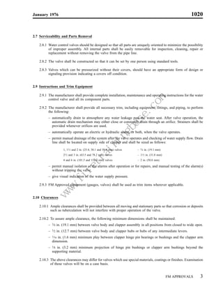
         – permit manual drainage of the system after the valve operates and checking of water supply flow. Drain
           line shall be located on supply side of clapper and shall be sized as follows:
                   1, 11⁄2 and 2 in. (25.4, 38.1 and 50.8 mm) valves   – 3⁄4 in. (19.1 mm)
                   21⁄2 and 3 in. (63.5 and 78.2 mm) valves            – 11⁄2 in. (31.8 mm)
                   4 and 6 in. (101.5 and 152.4 mm) valves             – 2 in. (50.8 mm)

         – permit manual isolation of the alarms after operation or for repairs, and manual testing of the alarm(s)
           without tripping the valve.
         – give visual indication of the water supply pressure.

   2.9.3 FM Approved equipment (gauges, valves) shall be used as trim items wherever applicable.
                                              m
                                          e.co


2.10 Clearances
                                         as
                                     gb
                                    in
                                in
                               ra
                          et
                        .fir
                    w
                    w
                   w


   2.10.1 Ample clearances shall be provided between all moving and stationary parts so that corrosion or deposits
          such as tuberculation will not interfere with proper operation of the valve.

   2.10.2 To assure ample clearance, the following minimum dimensions shall be maintained:
         – 3⁄4 in. (19.1 mm) between valve body and clapper assembly in all positions from closed to wide open.
         – 1⁄2 in. (12.7 mm) between valve body and clapper hubs or hubs of any intermediate levers.
         – 1⁄16 in. (1.6 mm) minimum play between clapper hinge pin bearings or bushings and the clapper arm
           dimension.
         – 1⁄8 in. (3.2 mm) minimum projection of hinge pin bushings or clapper arm bushings beyond the
           supporting material.

   2.10.3 The above clearances may differ for valves which use special materials, coatings or finishes. Examination
          of these valves will be on a case basis.


                                                                                              FM APPROVALS        3
1020                                                                                                        January 1976


III PERFORMANCE

3.1 General

    3.1.1 Water control valves may remain inactive for long periods of time, yet they must be ready and able to
          operate positively and reliably at any moment. Overall design should be uncomplicated and construction
          should be simple and rugged with appropriately generous dimensions and clearances.

    3.1.2 Water control valves and releasing devices shall be designed so that all movements of lever systems,
          diaphragms, valves and switches are positive and repeatable with no sluggishness. The releasing device
          shall be capable of providing twice the energy necessary to trip the valve under all conditions of system
          water pressure up to the rated working pressure.

    3.1.3 Valves may be designed for manual or automatic resetting.


3.2 Friction Loss

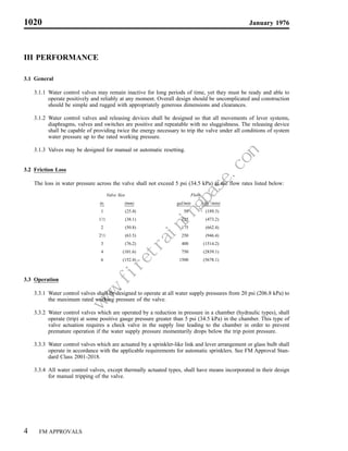
    The loss in water pressure across the valve shall not exceed 5 psi (34.5 kPa) at the flow rates listed below:
                                                               Valve Size                Flow
                                in.                                     (mm)     gal/min        (dm3/min)
                                      1                                 (25.4)      50           (189.3)
                                11⁄2                                    (38.1)     125           (473.2)
                                      2                                 (50.8)     175           (662.4)
                                21⁄2                                    (63.5)     250           (946.4)
                                      3                                 (76.2)     400          (1514.2)
                                      4                                (101.6)     750          (2839.1)
                                      6                                (152.4)    1500          (5678.1)


3.3 Operation

    3.3.1 Water control valves shall be designed to operate at all water supply pressures from 20 psi (206.8 kPa) to
          the maximum rated working pressure of the valve.
                                                           m
                                                       e.co
                                                      as
                                                  gb
                                                 in
                                             in
                                            ra
                                       et
                                     .fir
                                 w
                                 w


    3.3.2 Water control valves which are operated by a reduction in pressure in a chamber (hydraulic types), shall
                                w


          operate (trip) at some positive gauge pressure greater than 5 psi (34.5 kPa) in the chamber. This type of
          valve actuation requires a check valve in the supply line leading to the chamber in order to prevent
          premature operation if the water supply pressure momentarily drops below the trip point pressure.

    3.3.3 Water control valves which are actuated by a sprinkler-like link and lever arrangement or glass bulb shall
          operate in accordance with the applicable requirements for automatic sprinklers. See FM Approval Stan-
          dard Class 2001-2018.

    3.3.4 All water control valves, except thermally actuated types, shall have means incorporated in their design
          for manual tripping of the valve.


4     FM APPROVALS
January 1976                                                                                                  1020


IV TESTS

4.1 Operational Tests

    4.1.1 Sample valves will be set up and tripped by operating all of the release devices (manual and automatic
          methods) at various water supply pressures from 20 psi (206.8 kPa) to the rated working pressure of the
          valve. The valves shall operate smoothly and repeatably and shall meet the operational requirements of
          Paragraph 3.3.

    4.1.2 Special emphasis will be given to the installation and operating instructions provided by the manufacturer.
          The possibilities of malfunction due to misadjustment of parts or improper installation will be investigated.

    4.1.3 Thermal type devices utilizing sprinkler-like mechanisms shall be tested for operating temperature,
          response time and strength in accordance with normal sprinkler testing practice. Devices or mechanisms
          which are essentially the same as those used for approved sprinklers will require minimal retesting for this
          application.

    4.1.4 Special tests will be developed, as necessary, to evaluate operation of valves having special or unusual
          releasing mechanisms.


4.2 Friction Loss

    A sample valve will be installed between two test pipes of the same nominal diameter as the valve and equipped
    with piezometer rings. The pressure loss between the piezometers will be measured for sufficient flow rates to
    determine the friction loss characteristics of the valve. The friction loss shall meet the requirements of
    Paragraph 3.2.


4.3 Hydrostatic Tests

    4.3.1 The valve body will be subjected to a hydrostatic test of 700 psi (4.8 MPa) or 400% of the rated working
          pressure, whichever is greater, for 5 minutes. No fracture or permanent deformation shall result from this
          test.

    4.3.2 Valves which utilize clappers in their design will be subjected to a clapper strength test. With the clapper
          on its seat and the valve inlet open to atmosphere, a hydrostatic pressure of 200% of the rated working
          pressure will be applied to the outlet side of the clapper. No damage or function impairment shall result
                                                m
                                            e.co
                                           as
                                       gb
                                      in
                                  in
                                 ra
                            et
                          .fir


          from the test.
                      w
                      w
                     w


    4.3.3 Valves which use diaphragms in their design will be subjected to a diaphragm strength test. A differential
          pressure equal to 200% the rated working pressure of the valve will be applied across the diaphragm. No
          damage or function impairment shall result from this test.


4.4 Other Tests

    Depending on the particular design of the valve, other tests may be necessary to evaluate performance of the
    valve. This may include various tests on the rubber clapper facings, tests to evaluate the effects of chemical and
    galvanic corrosion on valve parts, and tests to evaluate the effects of environmental factors such as dust, dirt,
    vibration, or temperature.


                                                                                            FM APPROVALS             5

More Related Content

Viewers also liked

Viewers also liked (6)

Aerodynamic design of Aircraft”
Aerodynamic design of Aircraft”Aerodynamic design of Aircraft”
Aerodynamic design of Aircraft”
 
Nfpa 110
Nfpa 110Nfpa 110
Nfpa 110
 
NFPA 20
NFPA 20 NFPA 20
NFPA 20
 
2015 nfpa 70 e changes
2015 nfpa 70 e changes2015 nfpa 70 e changes
2015 nfpa 70 e changes
 
Nfpa 70 E
Nfpa 70 ENfpa 70 E
Nfpa 70 E
 
Aircraft propulsion (5)
Aircraft propulsion (5)Aircraft propulsion (5)
Aircraft propulsion (5)
 

Similar to Automatic Water Control Valve Approval Standard

Guidelines for Gas Tungsten Arc Welding (GTAW)
Guidelines for Gas Tungsten Arc Welding (GTAW)Guidelines for Gas Tungsten Arc Welding (GTAW)
Guidelines for Gas Tungsten Arc Welding (GTAW)Thomas Riggleman
 
Boiler control system engineering
Boiler control system engineeringBoiler control system engineering
Boiler control system engineeringHernan Coba
 
Gd300 user manual v1.1
Gd300 user manual v1.1Gd300 user manual v1.1
Gd300 user manual v1.1Toàn Huỳnh
 
Cummins onan c250 d5 generator set with power command 1.2 service repair manual
Cummins onan c250 d5 generator set with power command 1.2 service repair manualCummins onan c250 d5 generator set with power command 1.2 service repair manual
Cummins onan c250 d5 generator set with power command 1.2 service repair manualfjkfksmemm
 
Cummins onan c250 d5 generator set with power command 1.2 service repair manual
Cummins onan c250 d5 generator set with power command 1.2 service repair manualCummins onan c250 d5 generator set with power command 1.2 service repair manual
Cummins onan c250 d5 generator set with power command 1.2 service repair manualfksefkskemm
 
Cummins onan c250 d5 generator set with power command 1.2 service repair manual
Cummins onan c250 d5 generator set with power command 1.2 service repair manualCummins onan c250 d5 generator set with power command 1.2 service repair manual
Cummins onan c250 d5 generator set with power command 1.2 service repair manualfjjskefkksem
 
Krupp hydraulic hammers hm 1000 1000 marathon service repair manual
Krupp hydraulic hammers hm 1000  1000 marathon service repair manualKrupp hydraulic hammers hm 1000  1000 marathon service repair manual
Krupp hydraulic hammers hm 1000 1000 marathon service repair manualfjkskmmdmme
 
Cummins onan dfeg generator set with power command 3200 controller service re...
Cummins onan dfeg generator set with power command 3200 controller service re...Cummins onan dfeg generator set with power command 3200 controller service re...
Cummins onan dfeg generator set with power command 3200 controller service re...fksejfjskekmm
 
Cummins onan dfek generator set with power command 3200 controller service re...
Cummins onan dfek generator set with power command 3200 controller service re...Cummins onan dfek generator set with power command 3200 controller service re...
Cummins onan dfek generator set with power command 3200 controller service re...fksejfjskekmm
 
Cummins onan dfeg generator set with power command 3200 controller service re...
Cummins onan dfeg generator set with power command 3200 controller service re...Cummins onan dfeg generator set with power command 3200 controller service re...
Cummins onan dfeg generator set with power command 3200 controller service re...fjsekkmsem
 
Cummins onan dfeh generator set with power command 3200 controller service re...
Cummins onan dfeh generator set with power command 3200 controller service re...Cummins onan dfeh generator set with power command 3200 controller service re...
Cummins onan dfeh generator set with power command 3200 controller service re...fjjsekfkksefm
 

Similar to Automatic Water Control Valve Approval Standard (20)

Nfpa 1031
Nfpa 1031Nfpa 1031
Nfpa 1031
 
Nfpa 1021
Nfpa 1021Nfpa 1021
Nfpa 1021
 
Nfpa 1221
Nfpa 1221Nfpa 1221
Nfpa 1221
 
Nfpa 1045
Nfpa 1045Nfpa 1045
Nfpa 1045
 
Guidelines for Gas Tungsten Arc Welding (GTAW)
Guidelines for Gas Tungsten Arc Welding (GTAW)Guidelines for Gas Tungsten Arc Welding (GTAW)
Guidelines for Gas Tungsten Arc Welding (GTAW)
 
Boiler control system engineering
Boiler control system engineeringBoiler control system engineering
Boiler control system engineering
 
Water treatment
Water treatmentWater treatment
Water treatment
 
Gd300 user manual v1.1
Gd300 user manual v1.1Gd300 user manual v1.1
Gd300 user manual v1.1
 
Cummins onan c250 d5 generator set with power command 1.2 service repair manual
Cummins onan c250 d5 generator set with power command 1.2 service repair manualCummins onan c250 d5 generator set with power command 1.2 service repair manual
Cummins onan c250 d5 generator set with power command 1.2 service repair manual
 
Cummins onan c250 d5 generator set with power command 1.2 service repair manual
Cummins onan c250 d5 generator set with power command 1.2 service repair manualCummins onan c250 d5 generator set with power command 1.2 service repair manual
Cummins onan c250 d5 generator set with power command 1.2 service repair manual
 
Instruction manual SMC IDFA
Instruction manual SMC IDFAInstruction manual SMC IDFA
Instruction manual SMC IDFA
 
Power210 techbook en
Power210 techbook enPower210 techbook en
Power210 techbook en
 
Krupp hydraulic hammers hm 1000 1000 marathon service repair manual
Krupp hydraulic hammers hm 1000  1000 marathon service repair manualKrupp hydraulic hammers hm 1000  1000 marathon service repair manual
Krupp hydraulic hammers hm 1000 1000 marathon service repair manual
 
SR530F8 Solar Water Heating Project Controller
SR530F8 Solar Water Heating Project ControllerSR530F8 Solar Water Heating Project Controller
SR530F8 Solar Water Heating Project Controller
 
Nfpa 1032
Nfpa 1032Nfpa 1032
Nfpa 1032
 
Cummins onan dfeg generator set with power command 3200 controller service re...
Cummins onan dfeg generator set with power command 3200 controller service re...Cummins onan dfeg generator set with power command 3200 controller service re...
Cummins onan dfeg generator set with power command 3200 controller service re...
 
Cummins onan dfek generator set with power command 3200 controller service re...
Cummins onan dfek generator set with power command 3200 controller service re...Cummins onan dfek generator set with power command 3200 controller service re...
Cummins onan dfek generator set with power command 3200 controller service re...
 
Cummins onan dfeg generator set with power command 3200 controller service re...
Cummins onan dfeg generator set with power command 3200 controller service re...Cummins onan dfeg generator set with power command 3200 controller service re...
Cummins onan dfeg generator set with power command 3200 controller service re...
 
Cummins onan dfeh generator set with power command 3200 controller service re...
Cummins onan dfeh generator set with power command 3200 controller service re...Cummins onan dfeh generator set with power command 3200 controller service re...
Cummins onan dfeh generator set with power command 3200 controller service re...
 

More from Jianping Wong

Yang ming to_launch_japan_koreachinavietnam_service_kcv
Yang ming to_launch_japan_koreachinavietnam_service_kcvYang ming to_launch_japan_koreachinavietnam_service_kcv
Yang ming to_launch_japan_koreachinavietnam_service_kcvJianping Wong
 
Ym uasc and_cscl_merge_tp_services_for_winter_season
Ym uasc and_cscl_merge_tp_services_for_winter_seasonYm uasc and_cscl_merge_tp_services_for_winter_season
Ym uasc and_cscl_merge_tp_services_for_winter_seasonJianping Wong
 
Schneider logistics honors holland with 2013 ltl carrier of the year award
Schneider logistics honors holland with 2013 ltl carrier of the year awardSchneider logistics honors holland with 2013 ltl carrier of the year award
Schneider logistics honors holland with 2013 ltl carrier of the year awardJianping Wong
 
Reuse ny kcontainers_via_apcs_platform
Reuse ny kcontainers_via_apcs_platformReuse ny kcontainers_via_apcs_platform
Reuse ny kcontainers_via_apcs_platformJianping Wong
 
Nyk and yang ming reuse containers thanks to apcs platform
Nyk and yang ming reuse containers thanks to apcs platformNyk and yang ming reuse containers thanks to apcs platform
Nyk and yang ming reuse containers thanks to apcs platformJianping Wong
 
Seamless transitions are_they_possible
Seamless transitions are_they_possibleSeamless transitions are_they_possible
Seamless transitions are_they_possibleJianping Wong
 
521 announcement 29102013 interim financial report q3 2013
521  announcement 29102013  interim financial report q3 2013521  announcement 29102013  interim financial report q3 2013
521 announcement 29102013 interim financial report q3 2013Jianping Wong
 
Saia reports second quarter earnings per share of $0.72
Saia reports second quarter earnings per share of $0.72Saia reports second quarter earnings per share of $0.72
Saia reports second quarter earnings per share of $0.72Jianping Wong
 
Estes express lines announces general rate increase
Estes express lines announces general rate increaseEstes express lines announces general rate increase
Estes express lines announces general rate increaseJianping Wong
 
Top 10 popular express companies in us
Top 10 popular express companies in usTop 10 popular express companies in us
Top 10 popular express companies in usJianping Wong
 

More from Jianping Wong (19)

Yang ming to_launch_japan_koreachinavietnam_service_kcv
Yang ming to_launch_japan_koreachinavietnam_service_kcvYang ming to_launch_japan_koreachinavietnam_service_kcv
Yang ming to_launch_japan_koreachinavietnam_service_kcv
 
Ym uasc and_cscl_merge_tp_services_for_winter_season
Ym uasc and_cscl_merge_tp_services_for_winter_seasonYm uasc and_cscl_merge_tp_services_for_winter_season
Ym uasc and_cscl_merge_tp_services_for_winter_season
 
Schneider logistics honors holland with 2013 ltl carrier of the year award
Schneider logistics honors holland with 2013 ltl carrier of the year awardSchneider logistics honors holland with 2013 ltl carrier of the year award
Schneider logistics honors holland with 2013 ltl carrier of the year award
 
Reuse ny kcontainers_via_apcs_platform
Reuse ny kcontainers_via_apcs_platformReuse ny kcontainers_via_apcs_platform
Reuse ny kcontainers_via_apcs_platform
 
Nyk and yang ming reuse containers thanks to apcs platform
Nyk and yang ming reuse containers thanks to apcs platformNyk and yang ming reuse containers thanks to apcs platform
Nyk and yang ming reuse containers thanks to apcs platform
 
Seamless transitions are_they_possible
Seamless transitions are_they_possibleSeamless transitions are_they_possible
Seamless transitions are_they_possible
 
521 announcement 29102013 interim financial report q3 2013
521  announcement 29102013  interim financial report q3 2013521  announcement 29102013  interim financial report q3 2013
521 announcement 29102013 interim financial report q3 2013
 
Saia reports second quarter earnings per share of $0.72
Saia reports second quarter earnings per share of $0.72Saia reports second quarter earnings per share of $0.72
Saia reports second quarter earnings per share of $0.72
 
Estes express lines announces general rate increase
Estes express lines announces general rate increaseEstes express lines announces general rate increase
Estes express lines announces general rate increase
 
Top 10 popular express companies in us
Top 10 popular express companies in usTop 10 popular express companies in us
Top 10 popular express companies in us
 
Nfpa 1210
Nfpa 1210Nfpa 1210
Nfpa 1210
 
Nfpa 1111
Nfpa 1111Nfpa 1111
Nfpa 1111
 
Nfpa 1110
Nfpa 1110Nfpa 1110
Nfpa 1110
 
Nfpa 1055
Nfpa 1055Nfpa 1055
Nfpa 1055
 
Nfpa 1051
Nfpa 1051Nfpa 1051
Nfpa 1051
 
Nfpa 1046
Nfpa 1046Nfpa 1046
Nfpa 1046
 
Nfpa 1041
Nfpa 1041Nfpa 1041
Nfpa 1041
 
Nfpa 557
Nfpa 557Nfpa 557
Nfpa 557
 
Nfpa 1140
Nfpa 1140Nfpa 1140
Nfpa 1140
 

Recently uploaded

Full Stack Web Development Course for Beginners
Full Stack Web Development Course  for BeginnersFull Stack Web Development Course  for Beginners
Full Stack Web Development Course for BeginnersSabitha Banu
 
Introduction to ArtificiaI Intelligence in Higher Education
Introduction to ArtificiaI Intelligence in Higher EducationIntroduction to ArtificiaI Intelligence in Higher Education
Introduction to ArtificiaI Intelligence in Higher Educationpboyjonauth
 
ECONOMIC CONTEXT - LONG FORM TV DRAMA - PPT
ECONOMIC CONTEXT - LONG FORM TV DRAMA - PPTECONOMIC CONTEXT - LONG FORM TV DRAMA - PPT
ECONOMIC CONTEXT - LONG FORM TV DRAMA - PPTiammrhaywood
 
How to Configure Email Server in Odoo 17
How to Configure Email Server in Odoo 17How to Configure Email Server in Odoo 17
How to Configure Email Server in Odoo 17Celine George
 
Types of Journalistic Writing Grade 8.pptx
Types of Journalistic Writing Grade 8.pptxTypes of Journalistic Writing Grade 8.pptx
Types of Journalistic Writing Grade 8.pptxEyham Joco
 
Roles & Responsibilities in Pharmacovigilance
Roles & Responsibilities in PharmacovigilanceRoles & Responsibilities in Pharmacovigilance
Roles & Responsibilities in PharmacovigilanceSamikshaHamane
 
Atmosphere science 7 quarter 4 .........
Atmosphere science 7 quarter 4 .........Atmosphere science 7 quarter 4 .........
Atmosphere science 7 quarter 4 .........LeaCamillePacle
 
AMERICAN LANGUAGE HUB_Level2_Student'sBook_Answerkey.pdf
AMERICAN LANGUAGE HUB_Level2_Student'sBook_Answerkey.pdfAMERICAN LANGUAGE HUB_Level2_Student'sBook_Answerkey.pdf
AMERICAN LANGUAGE HUB_Level2_Student'sBook_Answerkey.pdfphamnguyenenglishnb
 
ECONOMIC CONTEXT - PAPER 1 Q3: NEWSPAPERS.pptx
ECONOMIC CONTEXT - PAPER 1 Q3: NEWSPAPERS.pptxECONOMIC CONTEXT - PAPER 1 Q3: NEWSPAPERS.pptx
ECONOMIC CONTEXT - PAPER 1 Q3: NEWSPAPERS.pptxiammrhaywood
 
Field Attribute Index Feature in Odoo 17
Field Attribute Index Feature in Odoo 17Field Attribute Index Feature in Odoo 17
Field Attribute Index Feature in Odoo 17Celine George
 
HỌC TỐT TIẾNG ANH 11 THEO CHƯƠNG TRÌNH GLOBAL SUCCESS ĐÁP ÁN CHI TIẾT - CẢ NĂ...
HỌC TỐT TIẾNG ANH 11 THEO CHƯƠNG TRÌNH GLOBAL SUCCESS ĐÁP ÁN CHI TIẾT - CẢ NĂ...HỌC TỐT TIẾNG ANH 11 THEO CHƯƠNG TRÌNH GLOBAL SUCCESS ĐÁP ÁN CHI TIẾT - CẢ NĂ...
HỌC TỐT TIẾNG ANH 11 THEO CHƯƠNG TRÌNH GLOBAL SUCCESS ĐÁP ÁN CHI TIẾT - CẢ NĂ...Nguyen Thanh Tu Collection
 
Crayon Activity Handout For the Crayon A
Crayon Activity Handout For the Crayon ACrayon Activity Handout For the Crayon A
Crayon Activity Handout For the Crayon AUnboundStockton
 
Framing an Appropriate Research Question 6b9b26d93da94caf993c038d9efcdedb.pdf
Framing an Appropriate Research Question 6b9b26d93da94caf993c038d9efcdedb.pdfFraming an Appropriate Research Question 6b9b26d93da94caf993c038d9efcdedb.pdf
Framing an Appropriate Research Question 6b9b26d93da94caf993c038d9efcdedb.pdfUjwalaBharambe
 
ACC 2024 Chronicles. Cardiology. Exam.pdf
ACC 2024 Chronicles. Cardiology. Exam.pdfACC 2024 Chronicles. Cardiology. Exam.pdf
ACC 2024 Chronicles. Cardiology. Exam.pdfSpandanaRallapalli
 
Gas measurement O2,Co2,& ph) 04/2024.pptx
Gas measurement O2,Co2,& ph) 04/2024.pptxGas measurement O2,Co2,& ph) 04/2024.pptx
Gas measurement O2,Co2,& ph) 04/2024.pptxDr.Ibrahim Hassaan
 
ENGLISH6-Q4-W3.pptxqurter our high choom
ENGLISH6-Q4-W3.pptxqurter our high choomENGLISH6-Q4-W3.pptxqurter our high choom
ENGLISH6-Q4-W3.pptxqurter our high choomnelietumpap1
 
Solving Puzzles Benefits Everyone (English).pptx
Solving Puzzles Benefits Everyone (English).pptxSolving Puzzles Benefits Everyone (English).pptx
Solving Puzzles Benefits Everyone (English).pptxOH TEIK BIN
 
ENGLISH 7_Q4_LESSON 2_ Employing a Variety of Strategies for Effective Interp...
ENGLISH 7_Q4_LESSON 2_ Employing a Variety of Strategies for Effective Interp...ENGLISH 7_Q4_LESSON 2_ Employing a Variety of Strategies for Effective Interp...
ENGLISH 7_Q4_LESSON 2_ Employing a Variety of Strategies for Effective Interp...JhezDiaz1
 
call girls in Kamla Market (DELHI) 🔝 >༒9953330565🔝 genuine Escort Service 🔝✔️✔️
call girls in Kamla Market (DELHI) 🔝 >༒9953330565🔝 genuine Escort Service 🔝✔️✔️call girls in Kamla Market (DELHI) 🔝 >༒9953330565🔝 genuine Escort Service 🔝✔️✔️
call girls in Kamla Market (DELHI) 🔝 >༒9953330565🔝 genuine Escort Service 🔝✔️✔️9953056974 Low Rate Call Girls In Saket, Delhi NCR
 

Recently uploaded (20)

Full Stack Web Development Course for Beginners
Full Stack Web Development Course  for BeginnersFull Stack Web Development Course  for Beginners
Full Stack Web Development Course for Beginners
 
Introduction to ArtificiaI Intelligence in Higher Education
Introduction to ArtificiaI Intelligence in Higher EducationIntroduction to ArtificiaI Intelligence in Higher Education
Introduction to ArtificiaI Intelligence in Higher Education
 
ECONOMIC CONTEXT - LONG FORM TV DRAMA - PPT
ECONOMIC CONTEXT - LONG FORM TV DRAMA - PPTECONOMIC CONTEXT - LONG FORM TV DRAMA - PPT
ECONOMIC CONTEXT - LONG FORM TV DRAMA - PPT
 
How to Configure Email Server in Odoo 17
How to Configure Email Server in Odoo 17How to Configure Email Server in Odoo 17
How to Configure Email Server in Odoo 17
 
Types of Journalistic Writing Grade 8.pptx
Types of Journalistic Writing Grade 8.pptxTypes of Journalistic Writing Grade 8.pptx
Types of Journalistic Writing Grade 8.pptx
 
Roles & Responsibilities in Pharmacovigilance
Roles & Responsibilities in PharmacovigilanceRoles & Responsibilities in Pharmacovigilance
Roles & Responsibilities in Pharmacovigilance
 
Atmosphere science 7 quarter 4 .........
Atmosphere science 7 quarter 4 .........Atmosphere science 7 quarter 4 .........
Atmosphere science 7 quarter 4 .........
 
AMERICAN LANGUAGE HUB_Level2_Student'sBook_Answerkey.pdf
AMERICAN LANGUAGE HUB_Level2_Student'sBook_Answerkey.pdfAMERICAN LANGUAGE HUB_Level2_Student'sBook_Answerkey.pdf
AMERICAN LANGUAGE HUB_Level2_Student'sBook_Answerkey.pdf
 
ECONOMIC CONTEXT - PAPER 1 Q3: NEWSPAPERS.pptx
ECONOMIC CONTEXT - PAPER 1 Q3: NEWSPAPERS.pptxECONOMIC CONTEXT - PAPER 1 Q3: NEWSPAPERS.pptx
ECONOMIC CONTEXT - PAPER 1 Q3: NEWSPAPERS.pptx
 
Field Attribute Index Feature in Odoo 17
Field Attribute Index Feature in Odoo 17Field Attribute Index Feature in Odoo 17
Field Attribute Index Feature in Odoo 17
 
9953330565 Low Rate Call Girls In Rohini Delhi NCR
9953330565 Low Rate Call Girls In Rohini  Delhi NCR9953330565 Low Rate Call Girls In Rohini  Delhi NCR
9953330565 Low Rate Call Girls In Rohini Delhi NCR
 
HỌC TỐT TIẾNG ANH 11 THEO CHƯƠNG TRÌNH GLOBAL SUCCESS ĐÁP ÁN CHI TIẾT - CẢ NĂ...
HỌC TỐT TIẾNG ANH 11 THEO CHƯƠNG TRÌNH GLOBAL SUCCESS ĐÁP ÁN CHI TIẾT - CẢ NĂ...HỌC TỐT TIẾNG ANH 11 THEO CHƯƠNG TRÌNH GLOBAL SUCCESS ĐÁP ÁN CHI TIẾT - CẢ NĂ...
HỌC TỐT TIẾNG ANH 11 THEO CHƯƠNG TRÌNH GLOBAL SUCCESS ĐÁP ÁN CHI TIẾT - CẢ NĂ...
 
Crayon Activity Handout For the Crayon A
Crayon Activity Handout For the Crayon ACrayon Activity Handout For the Crayon A
Crayon Activity Handout For the Crayon A
 
Framing an Appropriate Research Question 6b9b26d93da94caf993c038d9efcdedb.pdf
Framing an Appropriate Research Question 6b9b26d93da94caf993c038d9efcdedb.pdfFraming an Appropriate Research Question 6b9b26d93da94caf993c038d9efcdedb.pdf
Framing an Appropriate Research Question 6b9b26d93da94caf993c038d9efcdedb.pdf
 
ACC 2024 Chronicles. Cardiology. Exam.pdf
ACC 2024 Chronicles. Cardiology. Exam.pdfACC 2024 Chronicles. Cardiology. Exam.pdf
ACC 2024 Chronicles. Cardiology. Exam.pdf
 
Gas measurement O2,Co2,& ph) 04/2024.pptx
Gas measurement O2,Co2,& ph) 04/2024.pptxGas measurement O2,Co2,& ph) 04/2024.pptx
Gas measurement O2,Co2,& ph) 04/2024.pptx
 
ENGLISH6-Q4-W3.pptxqurter our high choom
ENGLISH6-Q4-W3.pptxqurter our high choomENGLISH6-Q4-W3.pptxqurter our high choom
ENGLISH6-Q4-W3.pptxqurter our high choom
 
Solving Puzzles Benefits Everyone (English).pptx
Solving Puzzles Benefits Everyone (English).pptxSolving Puzzles Benefits Everyone (English).pptx
Solving Puzzles Benefits Everyone (English).pptx
 
ENGLISH 7_Q4_LESSON 2_ Employing a Variety of Strategies for Effective Interp...
ENGLISH 7_Q4_LESSON 2_ Employing a Variety of Strategies for Effective Interp...ENGLISH 7_Q4_LESSON 2_ Employing a Variety of Strategies for Effective Interp...
ENGLISH 7_Q4_LESSON 2_ Employing a Variety of Strategies for Effective Interp...
 
call girls in Kamla Market (DELHI) 🔝 >༒9953330565🔝 genuine Escort Service 🔝✔️✔️
call girls in Kamla Market (DELHI) 🔝 >༒9953330565🔝 genuine Escort Service 🔝✔️✔️call girls in Kamla Market (DELHI) 🔝 >༒9953330565🔝 genuine Escort Service 🔝✔️✔️
call girls in Kamla Market (DELHI) 🔝 >༒9953330565🔝 genuine Escort Service 🔝✔️✔️
 

Automatic Water Control Valve Approval Standard

  • 1. Approval Standard for Automatic Water Control Valves Class Number 1020 January 1976 m e.co as gb in in ra et .fir w w w ©2002 FM Global Technologies LLC. All rights reserved.
  • 2. TABLE OF CONTENTS I. INTRODUCTION ...................................................................................................................................................................... 1 1.1 Scope ................................................................................................................................................................................. 1 II. GENERAL REQUIREMENTS .............................................................................................................................................. 1 2.1 Description .......................................................................................................................................................................... 1 2.2 Deluge and Preaction Systems ........................................................................................................................................... 2 2.3 Sizes .................................................................................................................................................................................... 2 2.4 Rated Working Pressure ..................................................................................................................................................... 2 2.5 End Connections ................................................................................................................................................................. 2 2.6 Materials and Construction ............................................................................................................................................... 2 2.7 Markings ............................................................................................................................................................................. 2 2.7 Serviceability and Parts Removal ...................................................................................................................................... 3 2.9 Instructions and Trim Equipment ....................................................................................................................................... 3 2.10 Clearances ......................................................................................................................................................................... 3 III PERFORMANCE ...................................................................................................................................................................... 4 3.1 General ................................................................................................................................................................................ 4 3.2 Friction Loss ....................................................................................................................................................................... 4 3.3 Operation ............................................................................................................................................................................. 4 IV TESTS .......................................................................................................................................................................................... 5 4.1 Operational Tests ................................................................................................................................................................ 5 4.2 Friction Loss ....................................................................................................................................................................... 5 4.3 Hydrostatic Tests ................................................................................................................................................................ 5 4.4 Other Tests .......................................................................................................................................................................... 5 m e.co as gb in in ra et .fir w w w
  • 3. January 1976 1020 I. INTRODUCTION 1.1 Scope 1.1 Automatic water control valves are used to control the flow of water for various fire protection applications. They are normally used in special sprinkler systems such as deluge and preaction systems; but are also used to control the flow to water spray systems, foam making equipment and other special purpose systems. 1.2 FM Approval is based on satisfactory evaluation of the product and the manufacturer in three major areas: – Examinations and tests on production samples are performed to evaluate (1) the suitability of the product, (2) the proper operation and performance of the product as specified by the manufacturer and required by FM Approvals, and (3) the durability and reliability of the product. – An examination of manufacturing facilities and quality control procedures is conducted to evaluate the manufacturer’s ability to produce the product which is examined and tested. These examinations are periodically repeated as part of FM Approvals’ product follow-up program. – Satisfactory field experience is the final test of Approval. Unsatisfactory field experience may neces- sitate withdrawal of FM Approval. 1.3 The requirements of this standard are intended as guidelines reflecting current FM Approval tests and practices. Devices which do not precisely conform to these requirements may be Approved if they meet the intent of this standard. Similarly, items that do conform to these requirements may not be Approved if they do not meet the intent of these requirements or if other conditions govern. II. GENERAL REQUIREMENTS 2.1 Description 2.1.1 Automatic water control valves are generally single clapper valves with the clapper maintained on its seat (‘‘set’’ position) mechanically by a system of levers. All valves are released by some means which is external to the valve; usually a mechanical, hydraulic, pneumatic, electrical, or thermal actuating system m e.co as gb in in ra et .fir or combination of these. w w w 2.1.2 Hydraulic type valves are maintained in the set position by system hydraulic pressure acting against a diaphragm connected to the mechanical members which actually hold the clapper closed. Releasing the pressure against the diaphragm trips the valve. 2.1.3 Mechanical type valves are released from the set position by some mechanical means. This is often done by the action of a released weight or by the activations or deactivations of an electrical device such as a solenoid. 2.1.4 Thermal type valves are released by heat from the fire acting on the valve itself. This valve utilizes a thermal device, such as a sprinkler-type link and lever arrangement or glass bulb, to hold the valve closed. Fusing the thermal device releases the valve clapper. FM APPROVALS 1
  • 4. 1020 January 1976 2.2 Deluge and Preaction Systems Automatic water control valves are often used in deluge and preaction systems. Valves used for these applica- tions must meet the requirements of this standard; but more importantly, the deluge or preaction system itself must meet the requirements of Approval Standard Class 1011-1012 (Deluge Systems and Preaction Systems). 2.3 Sizes Recognized standard sizes for water control valves are 1, 11⁄2, 2, 21⁄2, 3, 4 and 6 in. (25.4, 38.1, 50.8, 63.5, 76.2, 101.6 and 152.4). Other sizes may be approved, if they meet requirements and intent of this standard. 2.4 Rated Working Pressure Water control valves shall be designed for a rated working pressure of 175 psi (1206.6 kPa) or greater. 2.5 End Connections 2.5.1 Valve bodies of 3 in. (76.2 mm) and larger sizes shall have flanged ends conforming to a recognized national standard for flanged fittings, such as ANSI B16.5. Smaller valves may have flanged ends or threaded ends conforming to a recognized national standard for tapered pipe thread, such as ANSI B2.1. Other end connections may be approved if there is a demonstrated need for them, and these will be examined on a case-by-case basis. 2.5.2 Valves manufactured or for use outside North America may be approved with end connections conforming to national standards recognized in the country involved. 2.6 Materials and Construction 2.6.1 All materials used in water control valves shall be suitable for the intended purpose. Valve parts which could affect the operation of the valve if they became corroded or tuberculated shall be constructed of corrosion resistant materials. This includes such parts as hinge pin bushings and clapper arm bushings. Metal seat rings which come in contact with rubber seating surfaces shall be constructed of materials which will not naturally adhere to rubber. 2.6.2 All valve and release components shall be able to withstand the normal conditions of vibrations and m e.co as gb in in ra et .fir atmospheres associated with manufacturing and storage facilities, and be able to withstand the abuse w w w associated with normal installation and handling. 2.7 Markings A permanently installed, corrosion resistant nameplate, fastened to the valve in a prominent place shall contain the following information: manufacturer’s name or trademark, rated working pressure, nominal valve size, distinctive model designation, year of manufacture and the symbol of FM Approval. All or part of this marking may be cast in raised letters on the valve body. If the valves are manufactured at more than one location, each valve shall be uniquely marked to indicate place of origin. 2 FM APPROVALS
  • 5. January 1976 1020 2.7 Serviceability and Parts Removal 2.8.1 Water control valves should be designed so that all parts are uniquely oriented to minimize the possibility of improper assembly. All internal parts shall be easily removable for inspection, cleaning, repair or replacement without removing the valve from the pipe line. 2.8.2 The valve shall be constructed so that it can be set by one person using standard tools. 2.8.3 Valves which can be pressurized without their covers, should have an appropriate form of design or signaling provision indicating a covers off condition. 2.9 Instructions and Trim Equipment 2.9.1 The manufacturer shall provide complete installation, maintenance and operating instructions for the water control valve and all its component parts. 2.9.2 The manufacturer shall provide all necessary trim, including equipment, fittings, and piping, to perform the following: – automatically drain to atmosphere any water leakage past the water seat. After valve operation, the automatic drain mechanism may either close or constantly drain through an orifice. Strainers shall be provided whenever orifices are used. – automatically operate an electric or hydraulic alarm, or both, when the valve operates. – permit manual drainage of the system after the valve operates and checking of water supply flow. Drain line shall be located on supply side of clapper and shall be sized as follows: 1, 11⁄2 and 2 in. (25.4, 38.1 and 50.8 mm) valves – 3⁄4 in. (19.1 mm) 21⁄2 and 3 in. (63.5 and 78.2 mm) valves – 11⁄2 in. (31.8 mm) 4 and 6 in. (101.5 and 152.4 mm) valves – 2 in. (50.8 mm) – permit manual isolation of the alarms after operation or for repairs, and manual testing of the alarm(s) without tripping the valve. – give visual indication of the water supply pressure. 2.9.3 FM Approved equipment (gauges, valves) shall be used as trim items wherever applicable. m e.co 2.10 Clearances as gb in in ra et .fir w w w 2.10.1 Ample clearances shall be provided between all moving and stationary parts so that corrosion or deposits such as tuberculation will not interfere with proper operation of the valve. 2.10.2 To assure ample clearance, the following minimum dimensions shall be maintained: – 3⁄4 in. (19.1 mm) between valve body and clapper assembly in all positions from closed to wide open. – 1⁄2 in. (12.7 mm) between valve body and clapper hubs or hubs of any intermediate levers. – 1⁄16 in. (1.6 mm) minimum play between clapper hinge pin bearings or bushings and the clapper arm dimension. – 1⁄8 in. (3.2 mm) minimum projection of hinge pin bushings or clapper arm bushings beyond the supporting material. 2.10.3 The above clearances may differ for valves which use special materials, coatings or finishes. Examination of these valves will be on a case basis. FM APPROVALS 3
  • 6. 1020 January 1976 III PERFORMANCE 3.1 General 3.1.1 Water control valves may remain inactive for long periods of time, yet they must be ready and able to operate positively and reliably at any moment. Overall design should be uncomplicated and construction should be simple and rugged with appropriately generous dimensions and clearances. 3.1.2 Water control valves and releasing devices shall be designed so that all movements of lever systems, diaphragms, valves and switches are positive and repeatable with no sluggishness. The releasing device shall be capable of providing twice the energy necessary to trip the valve under all conditions of system water pressure up to the rated working pressure. 3.1.3 Valves may be designed for manual or automatic resetting. 3.2 Friction Loss The loss in water pressure across the valve shall not exceed 5 psi (34.5 kPa) at the flow rates listed below: Valve Size Flow in. (mm) gal/min (dm3/min) 1 (25.4) 50 (189.3) 11⁄2 (38.1) 125 (473.2) 2 (50.8) 175 (662.4) 21⁄2 (63.5) 250 (946.4) 3 (76.2) 400 (1514.2) 4 (101.6) 750 (2839.1) 6 (152.4) 1500 (5678.1) 3.3 Operation 3.3.1 Water control valves shall be designed to operate at all water supply pressures from 20 psi (206.8 kPa) to the maximum rated working pressure of the valve. m e.co as gb in in ra et .fir w w 3.3.2 Water control valves which are operated by a reduction in pressure in a chamber (hydraulic types), shall w operate (trip) at some positive gauge pressure greater than 5 psi (34.5 kPa) in the chamber. This type of valve actuation requires a check valve in the supply line leading to the chamber in order to prevent premature operation if the water supply pressure momentarily drops below the trip point pressure. 3.3.3 Water control valves which are actuated by a sprinkler-like link and lever arrangement or glass bulb shall operate in accordance with the applicable requirements for automatic sprinklers. See FM Approval Stan- dard Class 2001-2018. 3.3.4 All water control valves, except thermally actuated types, shall have means incorporated in their design for manual tripping of the valve. 4 FM APPROVALS
  • 7. January 1976 1020 IV TESTS 4.1 Operational Tests 4.1.1 Sample valves will be set up and tripped by operating all of the release devices (manual and automatic methods) at various water supply pressures from 20 psi (206.8 kPa) to the rated working pressure of the valve. The valves shall operate smoothly and repeatably and shall meet the operational requirements of Paragraph 3.3. 4.1.2 Special emphasis will be given to the installation and operating instructions provided by the manufacturer. The possibilities of malfunction due to misadjustment of parts or improper installation will be investigated. 4.1.3 Thermal type devices utilizing sprinkler-like mechanisms shall be tested for operating temperature, response time and strength in accordance with normal sprinkler testing practice. Devices or mechanisms which are essentially the same as those used for approved sprinklers will require minimal retesting for this application. 4.1.4 Special tests will be developed, as necessary, to evaluate operation of valves having special or unusual releasing mechanisms. 4.2 Friction Loss A sample valve will be installed between two test pipes of the same nominal diameter as the valve and equipped with piezometer rings. The pressure loss between the piezometers will be measured for sufficient flow rates to determine the friction loss characteristics of the valve. The friction loss shall meet the requirements of Paragraph 3.2. 4.3 Hydrostatic Tests 4.3.1 The valve body will be subjected to a hydrostatic test of 700 psi (4.8 MPa) or 400% of the rated working pressure, whichever is greater, for 5 minutes. No fracture or permanent deformation shall result from this test. 4.3.2 Valves which utilize clappers in their design will be subjected to a clapper strength test. With the clapper on its seat and the valve inlet open to atmosphere, a hydrostatic pressure of 200% of the rated working pressure will be applied to the outlet side of the clapper. No damage or function impairment shall result m e.co as gb in in ra et .fir from the test. w w w 4.3.3 Valves which use diaphragms in their design will be subjected to a diaphragm strength test. A differential pressure equal to 200% the rated working pressure of the valve will be applied across the diaphragm. No damage or function impairment shall result from this test. 4.4 Other Tests Depending on the particular design of the valve, other tests may be necessary to evaluate performance of the valve. This may include various tests on the rubber clapper facings, tests to evaluate the effects of chemical and galvanic corrosion on valve parts, and tests to evaluate the effects of environmental factors such as dust, dirt, vibration, or temperature. FM APPROVALS 5