Download to read offline

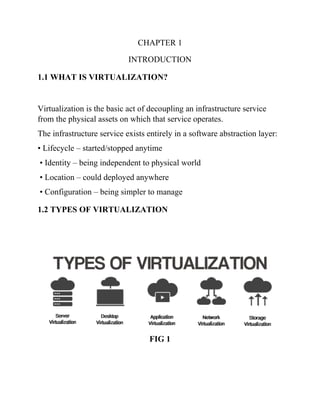
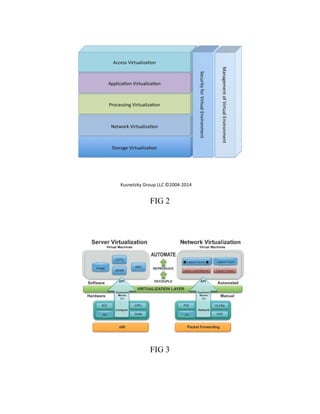
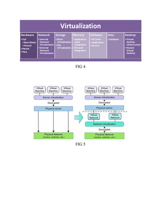
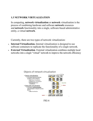
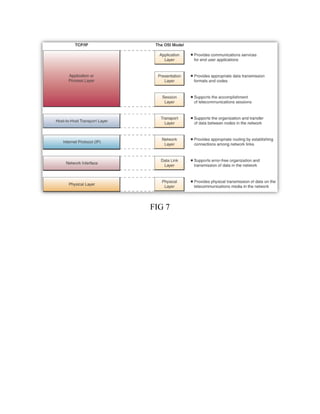

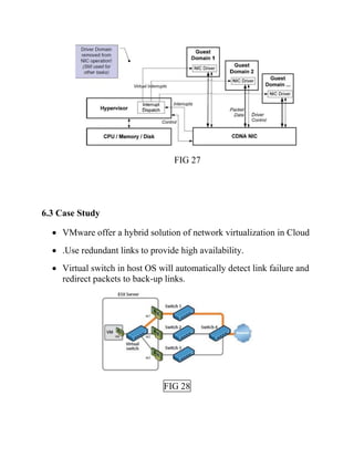

This document discusses network virtualization. It begins by defining virtualization as decoupling infrastructure services from physical hardware. There are two types of network virtualization: internal virtualization replicates network functionality within a single system, while external virtualization combines multiple networks. Network virtualization involves virtualizing network devices and communication paths between access points. Common virtualization techniques operate at layers 2-3 and include VLAN tagging, VPN tunneling, and overlay networks. The document also examines approaches to network virtualization in Xen and KVM virtualization systems and options for improving performance.