Instructor: Getahun Sh.(Msc)
Contactaddress: getahunshanko605@gmail.com
1
Ambo University Hachalu Hundessa Campus
School of Electrical Engineering and Computing
Department of Electrical and Computer Engineering
March, 2025
Lecture #
Network Analysis and 1
Chapter
One:-
Introduction to Network Analysis
and Synthesis
2.
Contents
• Basic definitionsand Representation
• Network Analysis and Synthesis
• ClassificationofNetworkElements
• Representation of Ideal Elements
2 Lecture #
Network Analysis and
3.
1.1. Basic definitionsand Representation of Networks
• A network is a collection/an interconnection of electrical
components to perform a certain task.
• An electric network is any possible interconnection of electric circuit
elements.
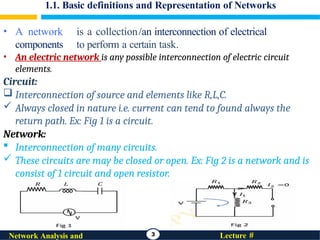
Circuit:
Interconnection of source and elements like R,L,C.
Always closed in nature i.e. current can tend to found always the
return path. Ex: Fig 1 is a circuit.
Network:
Interconnection of many circuits.
These circuits are may be closed or open. Ex: Fig 2 is a network and is
consist of 1 circuit and open resistor.
3 Lecture #
Network Analysis and
4.
1.1. Basic definitionsand Representation of Networks
• Network theory is the study of interrelationships among these variables and the
physical laws governing their behaviour.
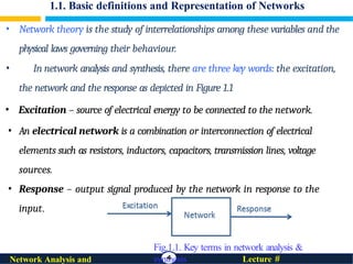
• In network analysis and synthesis, there are three key words: the excitation,
the network and the response as depicted in Figure 1.1
• Excitation – source of electrical energy to be connected to the network.
• An electrical network is a combination or interconnection of electrical
elements such as resistors, inductors, capacitors, transmission lines, voltage
sources.
• Response – output signal produced by the network in response to the
input.
Fig.1.1. Key terms in network analysis &
synthesis
4 Lecture #
Network Analysis and
5.
Con’t...
Network Analysis:
NetworkAnalysis is considered with determining the response, given
the excitation and the network .
If the network and the excitation are given, and the problem is to find
current or voltage across elements of the network.
• Always there is a solution
• But might be complex to find solution sometimes
• It focuses on understanding how components such as resistors,
capacitors, inductors, and voltage/current sources interact within a
circuit
5 Lecture #
Network Analysis and
6.
Con’t...
Network Synthesis :
Network Synthesis the problem is to design the network
given the excitation and the desired response.
• If the input and the output are given explicitly or implicitly and the
problem is to create a network that meets the given specifications,
the procedure followed is called network synthesis.
• Here the problem is to design/synthesize the network from the system
function:
R(s)
H(s)= E(s) given the excitation E(s) and the desired responseR(s).
It is designing and creating electrical networks or filters that meet specific
performance requirements.
6 Lecture #
Network Analysis and
7.
System
7 Lecture #
NetworkAnalysis and
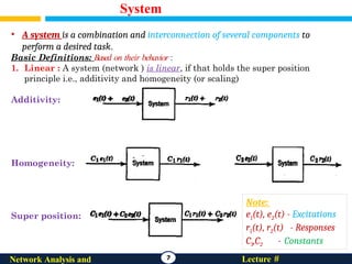
• A system is a combination and interconnection of several components to
perform a desired task.
Basic Definitions: Based on their behavior :
1. Linear : A system (network ) is linear, if that holds the super position
principle i.e., additivity and homogeneity (or scaling)
Additivity:
Homogeneity:
Super position:
Note:
e1(t), e2(t) - Excitations
r1(t), r2(t) - Responses
C1,C2 - Constants
8.
System Con’t...
8 Lecture#
Network Analysis and
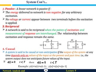
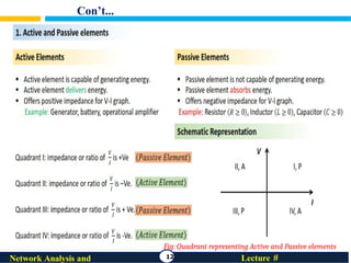
2. Passive : A linear network is passive if :
The energy delivered to network is non negative for any arbitrary
excitation.
No voltage or current appear between two terminals before the excitation
is applied.
3. Reciprocal
A network is said to be reciprocal when the points of excitation and
measurement of response are interchanged. The relationship between
excitation and response remain the same.
4. Causal
A system is said to be causal or non-anticipative if the output of the system at any
time depends only on values of the input at the present and past time. i.e., the
system output does not anticipate future values of the input.
If
9.
System Con’t...
9 Lecture#
Network Analysis and
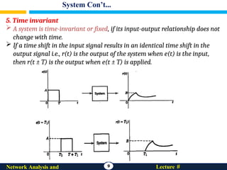
5. Time invariant
A system is time-invariant or fixed, if its input-output relationship does not
change with time.
If a time shift in the input signal results in an identical time shift in the
output signal i.e., r(t) is the output of the system when e(t) is the input,
then r(t ± T) is the output when e(t ± T) is applied.
10.
System Con’t...
10 Lecture#
Network Analysis and
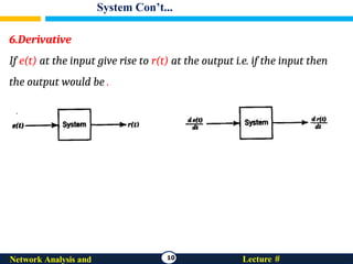
6.Derivative
If e(t) at the input give rise to r(t) at the output i.e. if the input then
the output would be .
11.
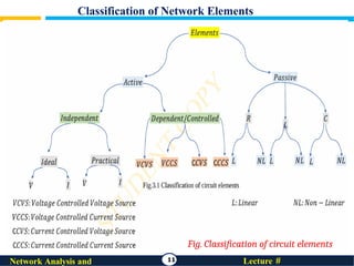
Classification of NetworkElements
11 Lecture #
Network Analysis and
Fig. Classification of circuit elements
Representation of Ideal
Elements
17Lecture #
Network Analysis and
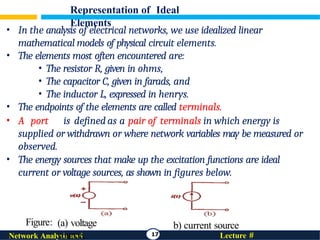
• In the analysis of electrical networks, we use idealized linear
mathematical models of physical circuit elements.
• The elements most often encountered are:
• The resistor R, given in ohms,
• The capacitor C, given in farads, and
• The inductor L, expressed in henrys.
• The endpoints of the elements are called terminals.
• A port is defined as a pair of terminals in which energy is
supplied or withdrawn or where network variables may be measured or
observed.
• The energy sources that make up the excitation functions are ideal
current or voltage sources, as shown in figures below.
(a) voltage
source,
b) current source
Figure:
18.
Cont…
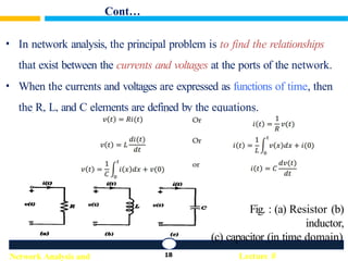
• In networkanalysis, the principal problem is to find the relationships
that exist between the currents and voltages at the ports of the network.
• When the currents and voltages are expressed as functions of time, then
the R, L, and C elements are defined by the equations.
Fig. : (a) Resistor (b)
inductor,
(c) capacitor (in time domain)
18 Lecture #
Network Analysis and
19.
Cont…
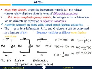
• In thetime domain, where the independent variable is t, the voltage-
current relationships are given in terms of differential equations.
• But, in the complex-frequency domain, the voltage-current relationships
for the elements are expressed in algebraic equations.
Algebraic equations are more easily solved than differential equations.
• The equationsdefiningthe R, L, and C elementscan be expressed
as a function of the frequency variables as follows using Laplace
transform.
Fig. : (a) Resistor, (b) inductor,
(c) capacitor (in Laplace domain)
19 Lecture #
Network Analysis and