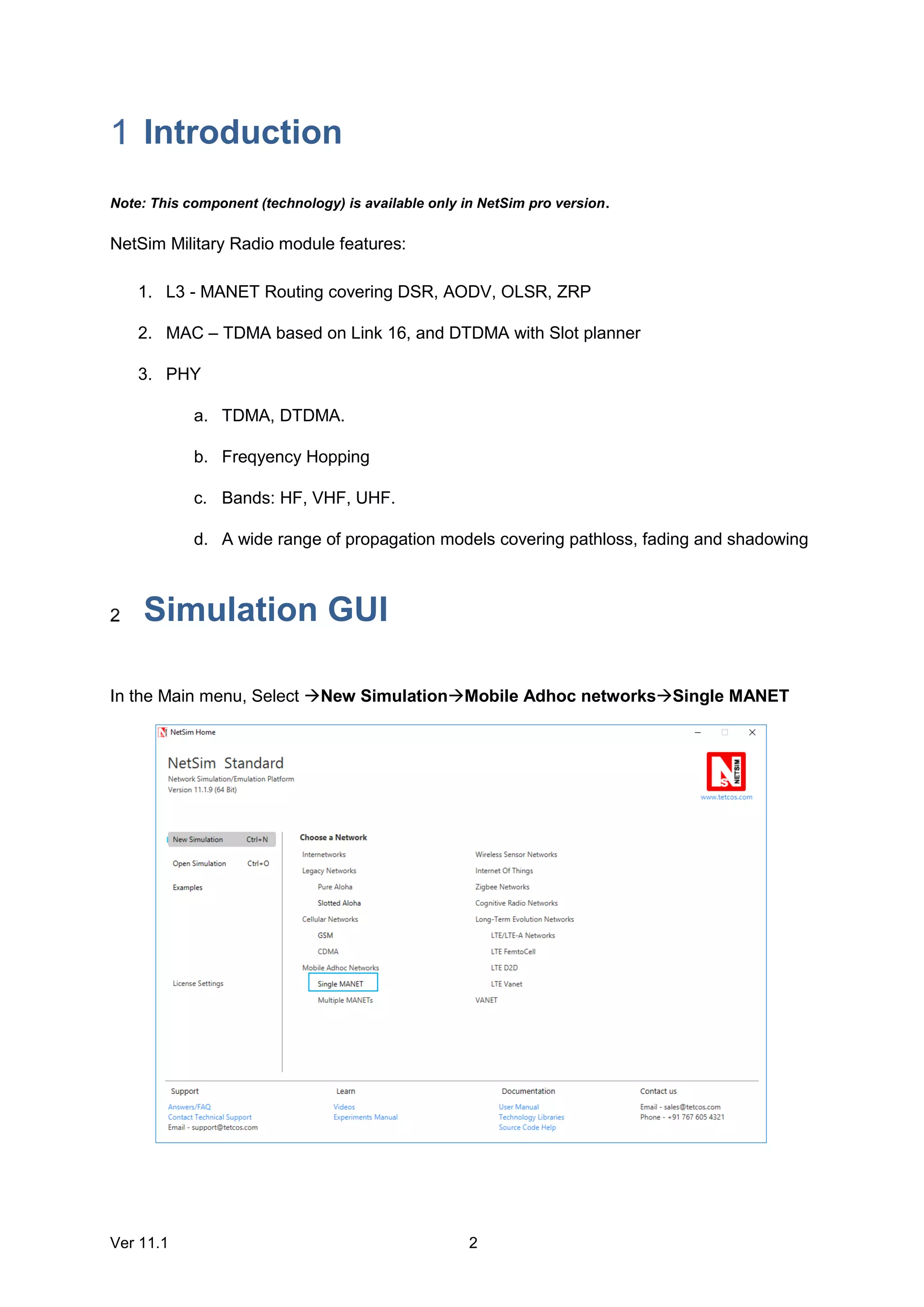
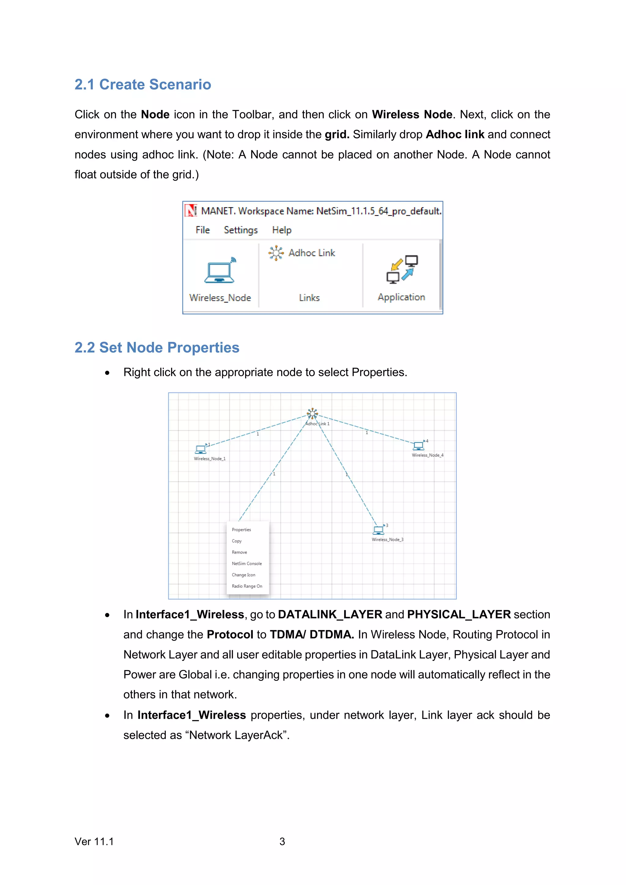
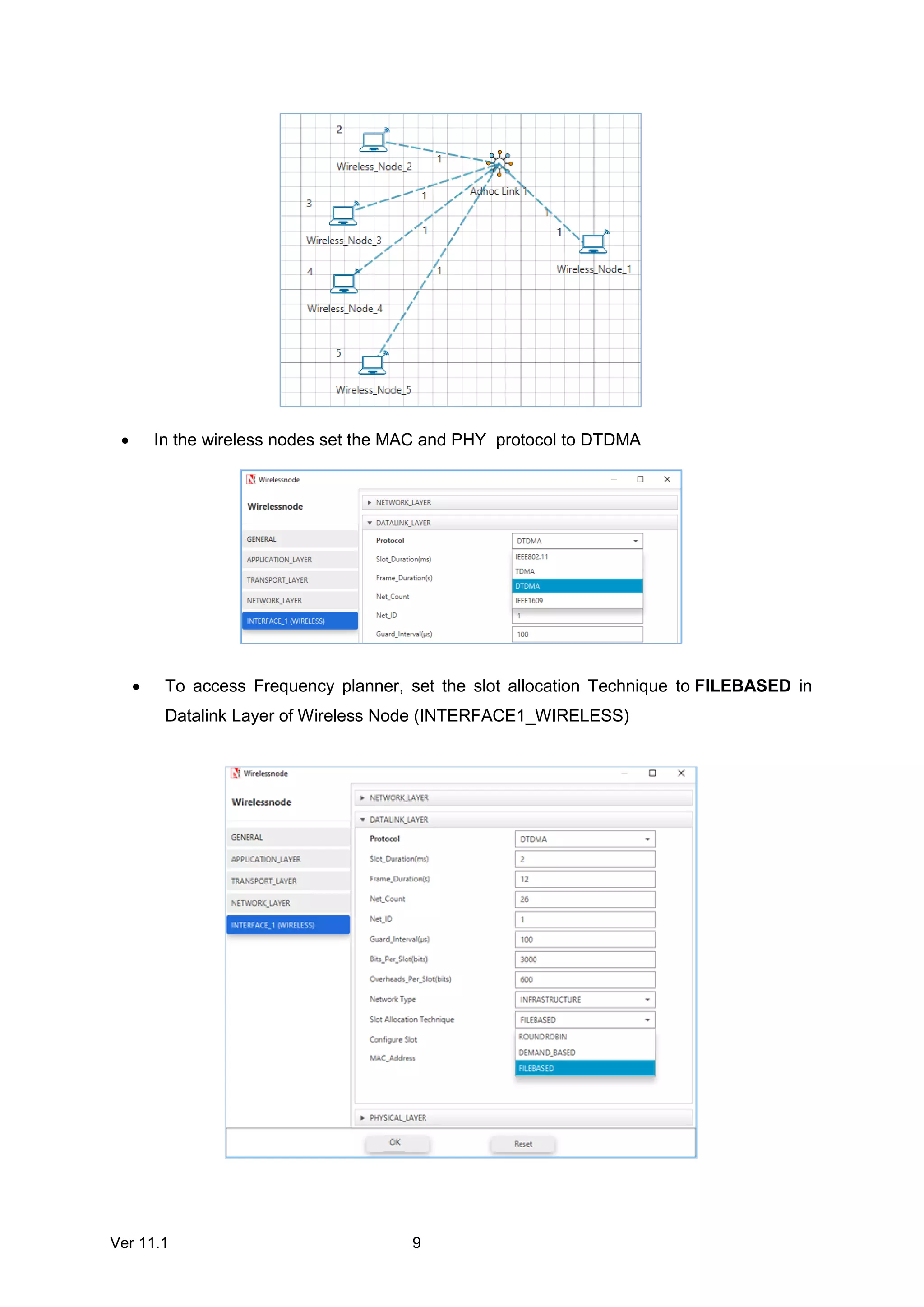
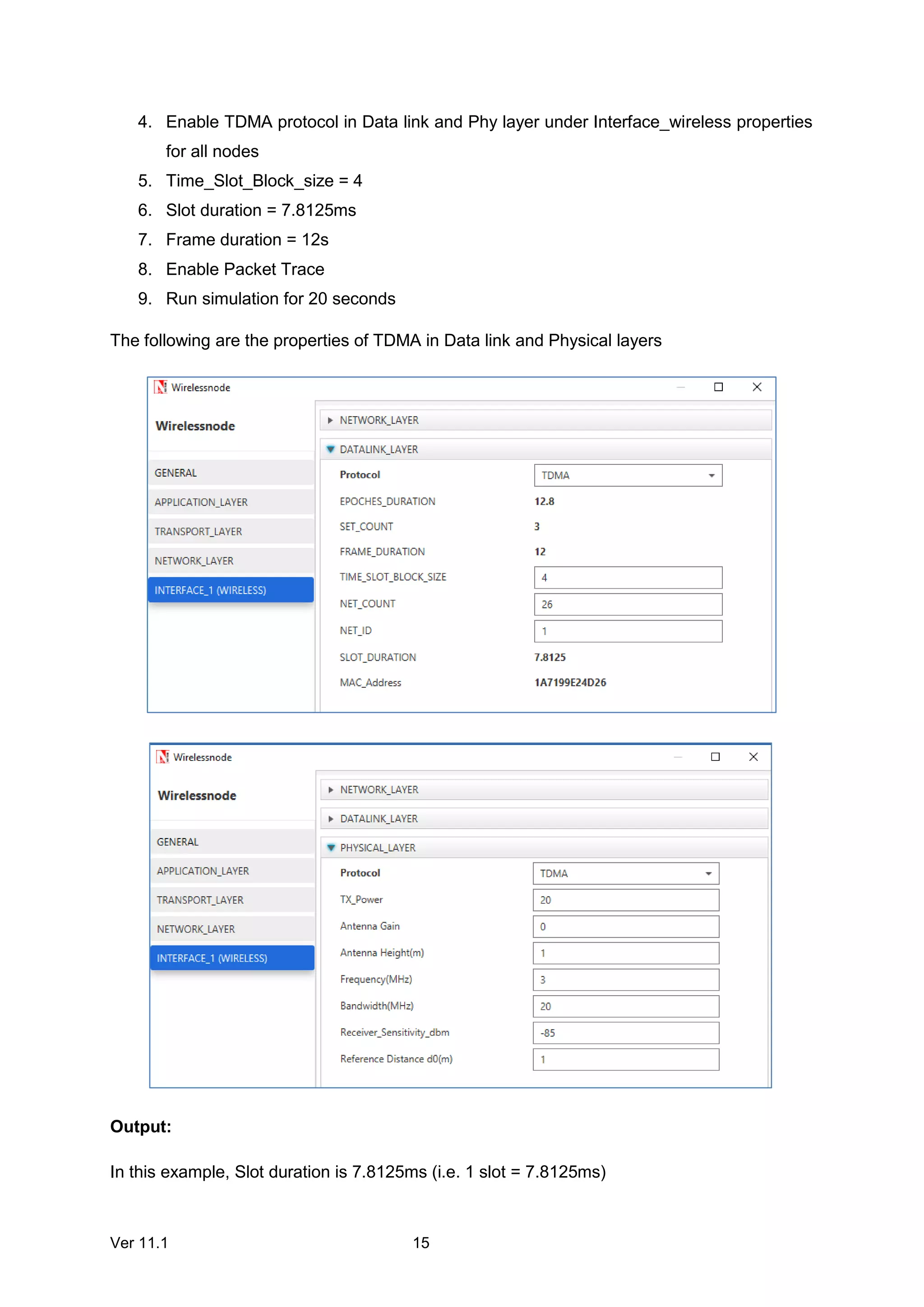
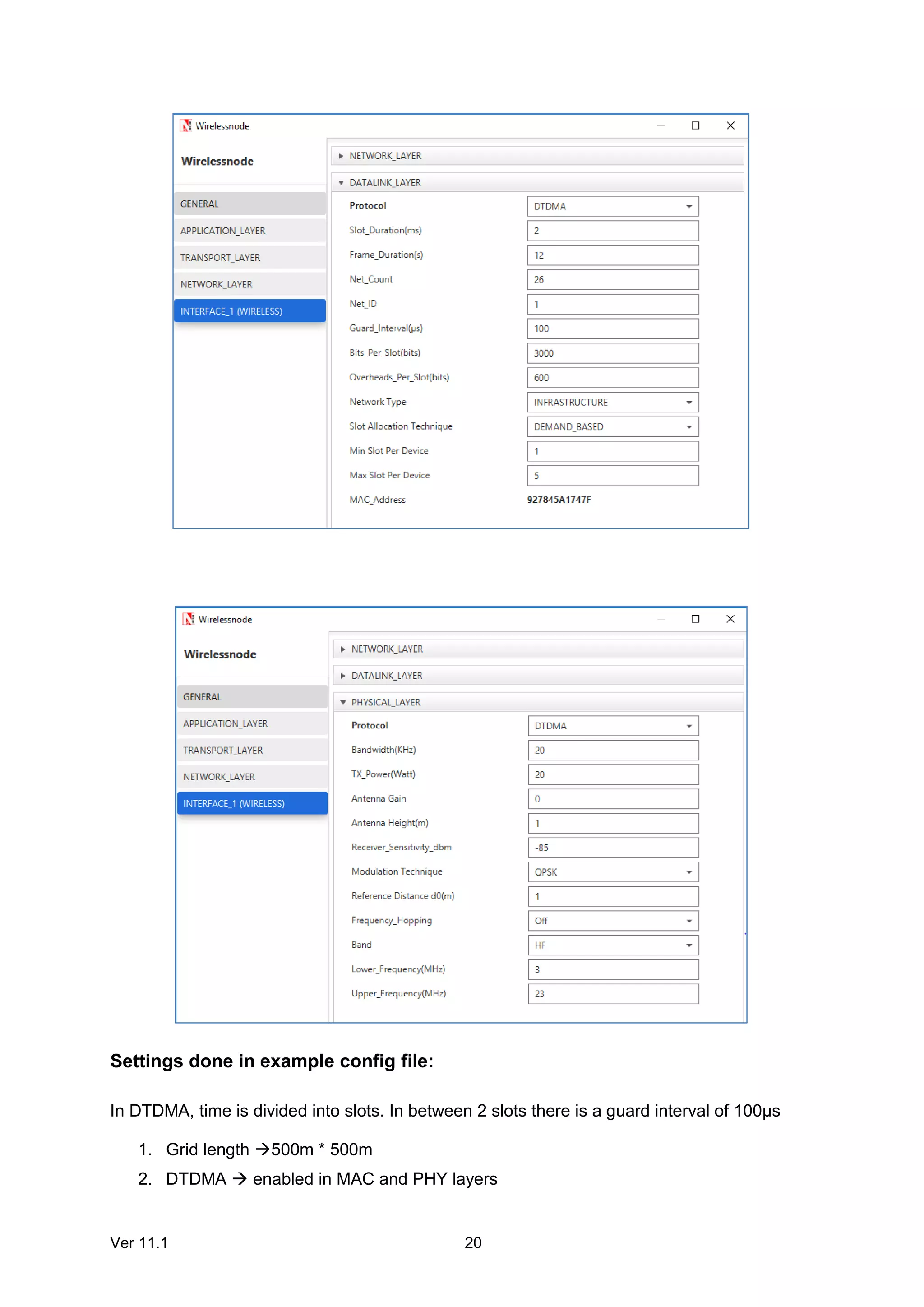
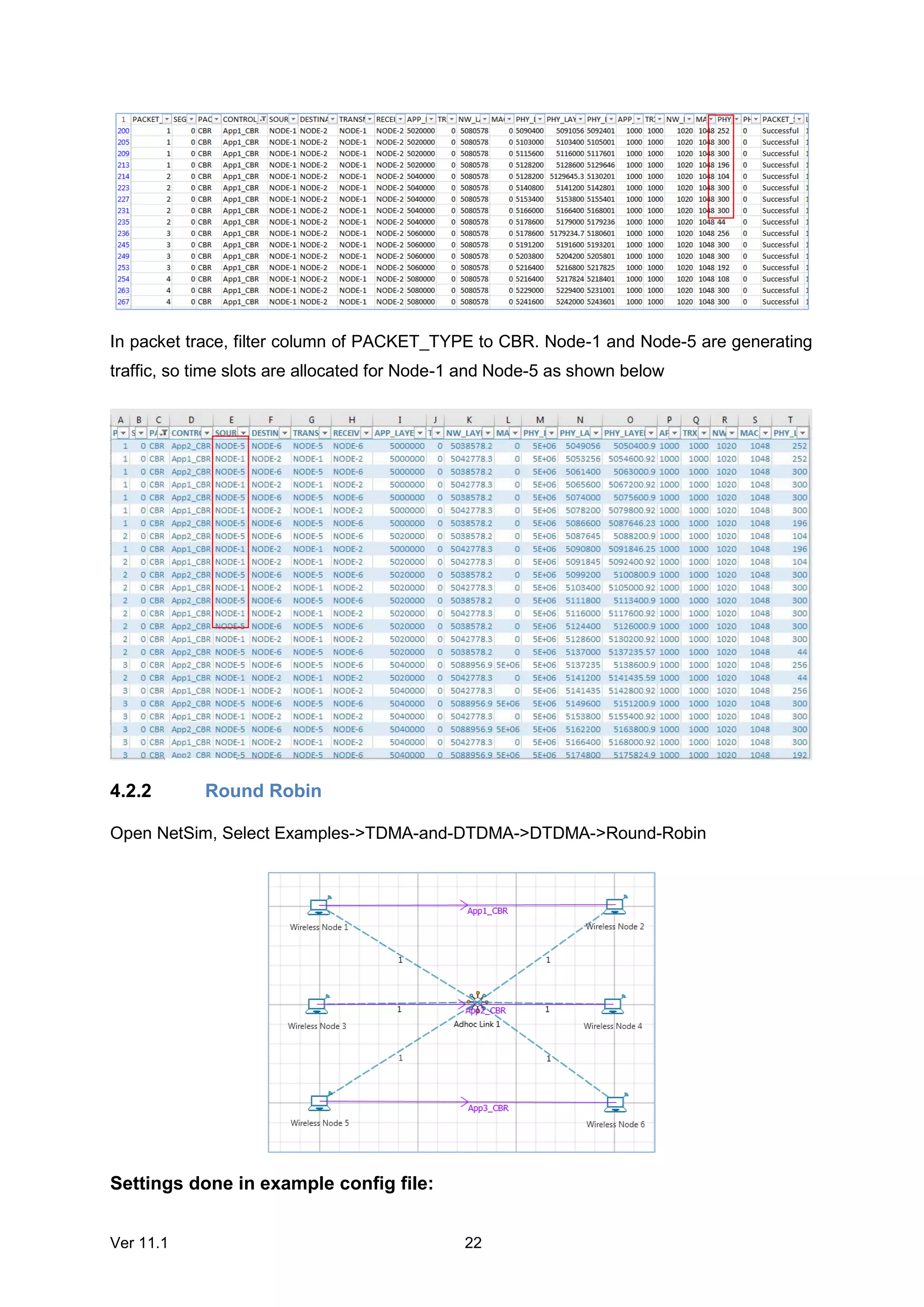
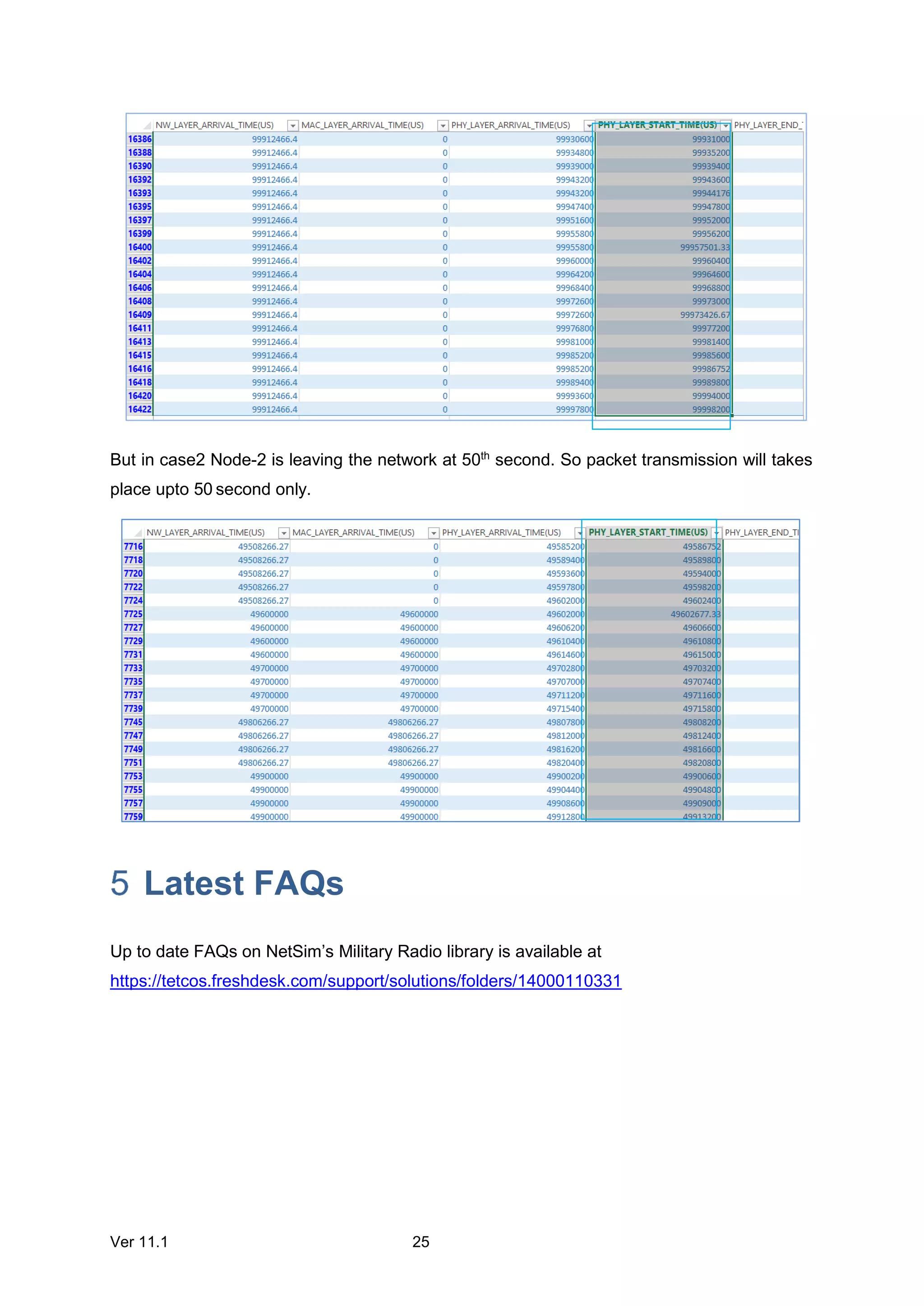
This document describes the features and usage of NetSim's military radio module, which supports TDMA and DTDMA protocols. It discusses how to set up a simulation scenario in NetSim, configure node and environment properties, run the simulation, and view results. Key features covered include node join/leave functionality, DTDMA packet size limits, and using the DTDMA slot planner to allocate slots to nodes in a predefined pattern. Example simulations demonstrate TDMA slot allocation and analyzing results, as well as DTDMA packet size analysis and round robin slot allocation.
Candidate Core Selection for Load-Balanced Multicore Shared Tree MulticastingKoushik Sinha
Multicasting can be done in two different ways: source based tree approach and shared tree approach. Protocols such as Core Based Tree (CBT), Protocol Independent Multicasting Sparse Mode (PIM-SM) use shared tree approach. Shared tree approach is preferred over source-based tree approach because in the later construction of minimum cost tree per source is needed unlike a single shared tree in the former approach. We present a candidate core selection approach for shared tree multicasting so that in a multicast session different senders can select different cores from the candidate core set based on the senders’ physical locations to allow an efficient multicore multicasting approach.
Paper reference link: https://www.researchgate.net/publication/303993360_Locality_based_Core_Selection_for_Multicore_Shared_Tree_Multicasting?ev=prf_pub
Introduction to Packet Radio, covering keyboard to keyboard QSOs, unproto mode, nodes, routing, digipeaters, packet via the ISS, APRS and WinLink.
Covers hardware TNCs as well as software soundmodems like UZ7HO and Direwolf
Multiuser MIMO-OFDM simulation framework in MatlabPavel Loskot
Simulation framework for multiuser MIMO-OFDM over multipath fading channels. Also created a C-like pre-processor in Matlab to add flexibility in configuring the simulation prior its run.
Cognitive Radio Network simulation is available from v7 of NetSim. Cognitive Radio Networks
allows you to connect, if required, with Ethernet, Wireless LAN, IP Routing, TCP / UDP and
allows users to log packet and event traces.
An internetwork is a collection of two or more computer networks (typically Local Area
Networks or LANs) which are interconnected to form a bigger network. All networks in an
Internetwork have a unique network address. Routers interconnect the networks
NetSim MANETs component can be interfaced with
Component 6 (IOT) module to run 802.15.4 in MAC/PHY
Component 9 (VANETs) module to run IEEE 1609 WAVE in MAC/PHY
Military Radio Add on to run TDMA/DTDMA in MAC/PHY
NetSim VANET library (https://www.tetcos.com) supports the following protocols
IEEE 802.11p, IEEE 1609 WAVE
Layer 3 Routing – AODV, DSR, OLSR, ZRP
PHY Layer RF Propagation
o Pathloss
o Shadowing
o Fading
Source C Code
Automatic import of road network and vehicles from SUMO
Wide range of output metrics including Delay, Throughput, Error, Retransmission,
etc.
Interfacing between SUMO & NetSim via Traffic control interface (TraCI).
NetSim Long Term Evolution (LTE) Networks library includes LTE/LTE-A networks, LTE
Femto Cell, LTE D2D and LTE VANET. The LTE libraray allows you to connect, if required,
with Internetwork devices such as Routers, Switches etc running Ethernet, Wireless LAN, IP
Routing, TCP / UDP.
Maharastra University electronics and Telecommunication Department NetSim (http://www.tetcos.com/ ) Experiment Manual , which can be done using NetSim Simulator , follow this Link :http://www.tetcos.com/
NetSim Technology Library - Software defined networksVishal Sharma
Software Defined Networking (SDN) module is featured from NetSim v11 onwards. This
module features an SDN controller which can be used to control packet forwarding of all Layer
3 devices in the Network.
A LAN or Local Area Network is a computer network (or data communications network) which is confined in a limited geographical location. A Virtual (or logical) LAN is a local area network with a definition that maps workstations/PCs on some other basis than geographic location (for example, by department, type of user or primary application)
In NetSim, you can simulate and analyze the following cellular netwoks: (Global System for Mobile communication) GSM and Code-Division Multiple Access (CDMA)
FEATURE and BENEFITS:
Hardware Architecture Providing
High Throughput Performance
and Repeatable Results /
Accuracy
Interface - 10/100/1000, 10GbE,
40GbE Copper or Fiber
Supports UDP, TCP, MPLS,
VLAN, ESP, LPD & Encrypted
Packets
Supports multiple links and
filtering of packets
Validate and Optimize your
Network before Deployment to
avoid Costly Application issues
Easy to use - Command Line
Interface with Scripting Support
or GUI Interface
Bandwidth - 300bps - 40GbE in
1bps increments
Delay - 0 ms to 10 sec. in
1ms increments, settings for
Constant, Uniform and Normal
Other Features - Real time traffic
graph and Network Statistics,
output reports
√ Approvals - UL, CSA, CE, FCC
and RoHS
2U Sturdy Rack Mount
Enclosure, 90-240VAC
Simulate Complete DNP3 Client / Master. using Serial, TCP/IP, UDP communication
Add up to 50 Client node in the simulator. Every Client node will work independently.
Binary Input, Double-bit Binary Input, Binary Output, Counter Input, Analog Input, Analog output, Octect String, virtual terminal String.
support CROB, analog output command with "select-before-operate" or "direct-execute" command execution modes
Industry proven, tested with all leading test tools
Features
Multiple Master / Client Simulation
Supports Serial, TCP, UDP Communication
Level 3 Compliance
Supports "Select-Before-Operate" SBO or "Direct-execute" command execution modes
Support File Transfer(File read, file write), Directory commands
Supports, frozen counter input, frozen analog input Groups
support Device Attributes
Supports unsolicited response, Octect String, Virtual Terminal Output
Transparent licensing scheme - No hidden costs, No deferred payments.
High performance, robust and scalable architecture
Support Binary Output(CROB) and Analog Output Commands
Industry Proven * tested with all leading test tools
The Customer can use the software company wide. Customer can install the software in many systems. There is no restriction like Hardware key (Dongle) and software key.
Students, digital devices and success - Andreas Schleicher - 27 May 2024..pptxEduSkills OECD
Andreas Schleicher presents at the OECD webinar ‘Digital devices in schools: detrimental distraction or secret to success?’ on 27 May 2024. The presentation was based on findings from PISA 2022 results and the webinar helped launch the PISA in Focus ‘Managing screen time: How to protect and equip students against distraction’ https://www.oecd-ilibrary.org/education/managing-screen-time_7c225af4-en and the OECD Education Policy Perspective ‘Students, digital devices and success’ can be found here - https://oe.cd/il/5yV
Operation “Blue Star” is the only event in the history of Independent India where the state went into war with its own people. Even after about 40 years it is not clear if it was culmination of states anger over people of the region, a political game of power or start of dictatorial chapter in the democratic setup.
The people of Punjab felt alienated from main stream due to denial of their just demands during a long democratic struggle since independence. As it happen all over the word, it led to militant struggle with great loss of lives of military, police and civilian personnel. Killing of Indira Gandhi and massacre of innocent Sikhs in Delhi and other India cities was also associated with this movement.
How to Split Bills in the Odoo 17 POS ModuleCeline George
Bills have a main role in point of sale procedure. It will help to track sales, handling payments and giving receipts to customers. Bill splitting also has an important role in POS. For example, If some friends come together for dinner and if they want to divide the bill then it is possible by POS bill splitting. This slide will show how to split bills in odoo 17 POS.
The Roman Empire A Historical Colossus.pdfkaushalkr1407
The Roman Empire, a vast and enduring power, stands as one of history's most remarkable civilizations, leaving an indelible imprint on the world. It emerged from the Roman Republic, transitioning into an imperial powerhouse under the leadership of Augustus Caesar in 27 BCE. This transformation marked the beginning of an era defined by unprecedented territorial expansion, architectural marvels, and profound cultural influence.
The empire's roots lie in the city of Rome, founded, according to legend, by Romulus in 753 BCE. Over centuries, Rome evolved from a small settlement to a formidable republic, characterized by a complex political system with elected officials and checks on power. However, internal strife, class conflicts, and military ambitions paved the way for the end of the Republic. Julius Caesar’s dictatorship and subsequent assassination in 44 BCE created a power vacuum, leading to a civil war. Octavian, later Augustus, emerged victorious, heralding the Roman Empire’s birth.
Under Augustus, the empire experienced the Pax Romana, a 200-year period of relative peace and stability. Augustus reformed the military, established efficient administrative systems, and initiated grand construction projects. The empire's borders expanded, encompassing territories from Britain to Egypt and from Spain to the Euphrates. Roman legions, renowned for their discipline and engineering prowess, secured and maintained these vast territories, building roads, fortifications, and cities that facilitated control and integration.
The Roman Empire’s society was hierarchical, with a rigid class system. At the top were the patricians, wealthy elites who held significant political power. Below them were the plebeians, free citizens with limited political influence, and the vast numbers of slaves who formed the backbone of the economy. The family unit was central, governed by the paterfamilias, the male head who held absolute authority.
Culturally, the Romans were eclectic, absorbing and adapting elements from the civilizations they encountered, particularly the Greeks. Roman art, literature, and philosophy reflected this synthesis, creating a rich cultural tapestry. Latin, the Roman language, became the lingua franca of the Western world, influencing numerous modern languages.
Roman architecture and engineering achievements were monumental. They perfected the arch, vault, and dome, constructing enduring structures like the Colosseum, Pantheon, and aqueducts. These engineering marvels not only showcased Roman ingenuity but also served practical purposes, from public entertainment to water supply.
2024.06.01 Introducing a competency framework for languag learning materials ...Sandy Millin
http://sandymillin.wordpress.com/iateflwebinar2024
Published classroom materials form the basis of syllabuses, drive teacher professional development, and have a potentially huge influence on learners, teachers and education systems. All teachers also create their own materials, whether a few sentences on a blackboard, a highly-structured fully-realised online course, or anything in between. Despite this, the knowledge and skills needed to create effective language learning materials are rarely part of teacher training, and are mostly learnt by trial and error.
Knowledge and skills frameworks, generally called competency frameworks, for ELT teachers, trainers and managers have existed for a few years now. However, until I created one for my MA dissertation, there wasn’t one drawing together what we need to know and do to be able to effectively produce language learning materials.
This webinar will introduce you to my framework, highlighting the key competencies I identified from my research. It will also show how anybody involved in language teaching (any language, not just English!), teacher training, managing schools or developing language learning materials can benefit from using the framework.
The Art Pastor's Guide to Sabbath | Steve ThomasonSteve Thomason
What is the purpose of the Sabbath Law in the Torah. It is interesting to compare how the context of the law shifts from Exodus to Deuteronomy. Who gets to rest, and why?
This is a presentation by Dada Robert in a Your Skill Boost masterclass organised by the Excellence Foundation for South Sudan (EFSS) on Saturday, the 25th and Sunday, the 26th of May 2024.
He discussed the concept of quality improvement, emphasizing its applicability to various aspects of life, including personal, project, and program improvements. He defined quality as doing the right thing at the right time in the right way to achieve the best possible results and discussed the concept of the "gap" between what we know and what we do, and how this gap represents the areas we need to improve. He explained the scientific approach to quality improvement, which involves systematic performance analysis, testing and learning, and implementing change ideas. He also highlighted the importance of client focus and a team approach to quality improvement.
We all have good and bad thoughts from time to time and situation to situation. We are bombarded daily with spiraling thoughts(both negative and positive) creating all-consuming feel , making us difficult to manage with associated suffering. Good thoughts are like our Mob Signal (Positive thought) amidst noise(negative thought) in the atmosphere. Negative thoughts like noise outweigh positive thoughts. These thoughts often create unwanted confusion, trouble, stress and frustration in our mind as well as chaos in our physical world. Negative thoughts are also known as “distorted thinking”.
NetSim Technology Library- Military radio-tdma-and-dtdma
1. Ver 11.1 1
Military Radio – TDMA / DTDMA
Contents
Introduction..........................................................................................................................2
Simulation GUI......................................................................................................................2
2.1 Create Scenario..........................................................................................................................3
2.2 Set Node Properties...................................................................................................................3
2.3 Set Environment Properties ......................................................................................................4
2.4 Set Application Properties.........................................................................................................5
2.5 Enable Packet Trace, Event Trace & Plots (Optional)................................................................6
2.6 Run Simulation...........................................................................................................................6
Model Features.....................................................................................................................7
3.1 Node Join / Leave ......................................................................................................................7
3.2 DTDMA Packet size....................................................................................................................7
3.3 DTDMA Slot Planner..................................................................................................................8
Featured Examples..............................................................................................................14
4.1 TDMA.......................................................................................................................................14
4.1.1 Slot Allocation.........................................................................................................14
4.2 DTDMA.....................................................................................................................................18
4.2.1 Packet size and Slot Allocation Analysis.................................................................19
4.2.2 Round Robin ...........................................................................................................22
4.2.3 Node Join and Node Leave.....................................................................................24
Latest FAQs.........................................................................................................................25
2. Ver 11.1 2
Introduction
Note: This component (technology) is available only in NetSim pro version.
NetSim Military Radio module features:
1. L3 - MANET Routing covering DSR, AODV, OLSR, ZRP
2. MAC – TDMA based on Link 16, and DTDMA with Slot planner
3. PHY
a. TDMA, DTDMA.
b. Freqyency Hopping
c. Bands: HF, VHF, UHF.
d. A wide range of propagation models covering pathloss, fading and shadowing
Simulation GUI
In the Main menu, Select New SimulationMobile Adhoc networksSingle MANET
3. Ver 11.1 3
2.1 Create Scenario
Click on the Node icon in the Toolbar, and then click on Wireless Node. Next, click on the
environment where you want to drop it inside the grid. Similarly drop Adhoc link and connect
nodes using adhoc link. (Note: A Node cannot be placed on another Node. A Node cannot
float outside of the grid.)
2.2 Set Node Properties
Right click on the appropriate node to select Properties.
In Interface1_Wireless, go to DATALINK_LAYER and PHYSICAL_LAYER section
and change the Protocol to TDMA/ DTDMA. In Wireless Node, Routing Protocol in
Network Layer and all user editable properties in DataLink Layer, Physical Layer and
Power are Global i.e. changing properties in one node will automatically reflect in the
others in that network.
In Interface1_Wireless properties, under network layer, Link layer ack should be
selected as “Network LayerAck”.
4. Ver 11.1 4
Furthermore, in Physical layer, we can select the frequency bands (HF/VHF/UHF). Users can
modify the lower frequency range and the Bandwidth. The sum of the Lower frequency and
Bandwidth gives the Upper frequency. Users can also select the modulation techniques such
as QPSK/16-QAM/64-QAM and, an option to turn ON/OFF frequency hopping is also
provided.
2.3 Set Environment Properties
Right click on Adhoc link and select Properties.
Select the Channel Characteristics and set the parameters accordingly.
5. Ver 11.1 5
2.4 Set Application Properties
Click on the Application icon present on the ribbon and set properties.Multiple
applications can be generated by using add button in Application properties.
Set the values according to requirement and click OK.
6. Ver 11.1 6
Note: Maximum Packet Size in TDMA is 48 bytes.
2.5 Enable Packet Trace, Event Trace & Plots (Optional)
Click Packet Trace / Event Trace icon in the tool bar and check Enable Packet Trace / Event
Trace check box and click OK. To get detailed help, please refer sections 7.5 and 7.6 in User
Manual. Select Plots icon for enabling Plots and click OK.
2.6 Run Simulation
Click on Run Simulation icon on the top toolbar.
7. Ver 11.1 7
Set the Simulation Time and click on OK.
Model Features
3.1 Node Join / Leave
Node join(s) - It is the time at which the node join the network and accesses the
communication channel.
Node leave (s) – It is the time at which the node leaves the network.
Plots will be shown only for the period in which the node is present in the network. For example,
if node join = 0, node leave = 5, even if the simulation time = 100s, the Plots will be shown
only for 5s.
Use case: Fields can take multiple inputs separated by comma as shown below:
Node join - 0, 10
Node leave - 5, 100
In this case, the node joins the network at 0s and leaves at 5s and the node joins the network
again at 10s and leaves at 100s.
3.2 DTDMA Packet size
It is important to set packet size (of any application running over DTDMA) to be lower than the
Max packet Size setting indicated below. If the packet size exceeds the Max Packet Size
setting then DTDMA would not be able to transmit that packet.
Maximum Packet size (bytes) =
𝐵𝑖𝑡𝑠 𝑝𝑒𝑟 𝑠𝑙𝑜𝑡−𝑜𝑣𝑒𝑟ℎ𝑒𝑎𝑑 𝑝𝑒𝑟 𝑠𝑙𝑜𝑡−𝑇𝑥 𝐿𝑎𝑦𝑒𝑟 𝑂𝐻−𝑁𝑊 𝑙𝑎𝑦𝑒𝑟 𝑂𝐻
8
By default,
Bits per slot (bits) – 3000, Overhead per slot (bits) - 600
Users can also edit the values of Bits per slot and Overhead per slot in the GUI.
Assuming default values are chosen for Bits per slot and Overhead per slot, DTDMA packet
size is calculated for different protocols as shown below:
8. Ver 11.1 8
i. For DSR protocol (if TCP is enabled),
DSR overhead (one hop) - 12 bytes which is added with Network layer overheads, plus
IP overhead of 20 plus TCP Overhead of 20, totaling 52 bytes (416 bits).
Max Packet size (bytes) = 𝐵𝑖𝑡𝑠 𝑝𝑒𝑟 𝑠𝑙𝑜𝑡−𝑜𝑣𝑒𝑟ℎ𝑒𝑎𝑑 𝑝𝑒𝑟 𝑠𝑙𝑜𝑡−416
8
= 248 bytes
ii. For DSR protocol (if UDP is enabled),
DSR overhead (one hop) - 12 bytes which is added with Network layer overheads, plus IP
overhead of 20 plus UDP Overhead of 8, totaling 40 bytes (320 bits).
Max Packet size (bytes) = 𝐵𝑖𝑡𝑠 𝑝𝑒𝑟 𝑠𝑙𝑜𝑡−𝑜𝑣𝑒𝑟ℎ𝑒𝑎𝑑 𝑝𝑒𝑟 𝑠𝑙𝑜𝑡−320
8
= 260 bytes
iii. For AODV, ZRP, OLSR protocol (if TCP is enabled),
Here AODV, ZRP, OLSR overhead – 0 (no overhead is added) plus IP overhead of 20 plus
TCP Overhead of 20, totaling 40 bytes (320 bits)
Max Packet size (bytes) = 𝐵𝑖𝑡𝑠 𝑝𝑒𝑟 𝑠𝑙𝑜𝑡−𝑜𝑣𝑒𝑟ℎ𝑒𝑎𝑑 𝑝𝑒𝑟 𝑠𝑙𝑜𝑡−320
8
= 260 bytes
iv. For AODV, ZRP, OLSR protocol (if UDP is enabled),
Here AODV, ZRP, OLSR overhead – 0 (no overhead is added) plus IP overhead of 20 plus
UDP Overhead of 8, totaling 40 bytes (224 bits)
Max Packet size (bytes) = 𝐵𝑖𝑡𝑠 𝑝𝑒𝑟 𝑠𝑙𝑜𝑡−𝑜𝑣𝑒𝑟ℎ𝑒𝑎𝑑 𝑝𝑒𝑟 𝑠𝑙𝑜𝑡−224
8
= 272 bytes
3.3 DTDMA Slot Planner
How to use the DTDMA slot planner?
Slot planner can be used to configure a predefined slot allocation pattern for the nodes in the
network. Based on the configuration done, slots will be allocated to the devices during the
simulation. Multiple/continuous slots can be allocated to the same node or to different nodes
as per the requirement.
Create a network scenario in NetSim Single MANET through Manually via click and
drop or open NetSim, Select Examples->TDMA-and-DTDMA->DTDMA->DTDMA-
Slot-Planner”
9. Ver 11.1 9
In the wireless nodes set the MAC and PHY protocol to DTDMA
To access Frequency planner, set the slot allocation Technique to FILEBASED in
Datalink Layer of Wireless Node (INTERFACE1_WIRELESS)
10. Ver 11.1 10
Click on the OPEN_SLOT_PLANNER link to get the Frequency Planner window
To set the slot allocation patter, enter the Number of slots in the text box and click
on OK
If you prefer to allocate slots to all devices in the network, you will have to enter the
number of slots equivalent or greater than the number of devices in your network
scenario. The pattern defined by the user will be repeated throughout the simulation
11. Ver 11.1 11
Use the radio buttons to allocate a specific slot to a particular device matching the row
which contains the device name and column which contains the slot id
Here the slots are allocated in the order, Wireless_Node_1,3,4,2 and 5
Click on Submit button to apply the configured pattern
Create 4 CBR_Application with default settings from Wireless Node_2, 3, 4, 5 to1
Enable the Plots, packet trace and event trace options and run the simulation for
100sec
Results:
12. Ver 11.1 12
At the end of the simulation click on the Open Event Trace option in the simulation
results window to access the event trace
Once the event trace is loaded and formatted as table in excel as shown below
In the column Subevent_Type, filter apply filter by selecting only
DTDMA_SCHEDULE_Transmission
13. Ver 11.1 13
After applying the filter, in the column Device_Id you will be able to observe the slot
allocation pattern as per the configuration done in GUI. Wireless_Node_1, 3, 4, 2
and 5
DTDMA_Slot_Planner for Multiple MANETs:
In the similar way slot allocation pattern can be defined for Multiple MANETs also.
Here you will have multiple tables in the slot planner, corresponding to each MANET
14. Ver 11.1 14
Featured Examples
Sample configuration files for all networks are available in Examples Menu in NetSim Home
Screen. These files provide examples on how NetSim can be used – the parameters that can
be changed and the typical effect it has on performance.
4.1 TDMA
Time division multiple access (TDMA) is a channel access method for shared medium
networks. It allows several users to share the same frequency channel by dividing the signal
into different time slots. The users transmit in rapid succession, one after the other, each using
its own time slot. This allows multiple stations to share the same transmission medium (e.g.
radio frequency channel) while using only a part of its channel capacity.
4.1.1 Slot Allocation
Open NetSim, Select Examples->TDMA-and-DTDMA->TDMA->TDMA-Slot-Allocation
Settings done in the Network:
1. Grid length: 500m*500m
2. Configure CBR application with Packet Size = 48Bytes, IAT = 20000µs
3. Set start time as 0 in application properties
15. Ver 11.1 15
4. Enable TDMA protocol in Data link and Phy layer under Interface_wireless properties
for all nodes
5. Time_Slot_Block_size = 4
6. Slot duration = 7.8125ms
7. Frame duration = 12s
8. Enable Packet Trace
9. Run simulation for 20 seconds
The following are the properties of TDMA in Data link and Physical layers
Output:
In this example, Slot duration is 7.8125ms (i.e. 1 slot = 7.8125ms)
16. Ver 11.1 16
Slot Duration = 7.8125 ms
Total No. of slots for 1 Second = 128 Slots
Frame Duration = 12 Seconds
Total No. of slots per frame = 128 * 12 = 1536 Slots
At the end of any simulation, the slot allocation can be observed in TDMA_ALLOCATION text
doc created in NetSim folder present in the system temporary (%temp%NetSim) directory
shown below:
In the above screenshot columns 1, 2, 3, 4 and 5 specify NET_ID, Frame_ID, Start_Slot_ID,
End_Slot_ID and Node_ID respectively.
Slots 1-4 are allocated to Node1,
Slots 5-8 are allocated to Node2,
17. Ver 11.1 17
Slots 9-12 are allocated to Node3,
Slots 13-16 are allocated to Node4,
Slots 17-20 are allocated to Node5,
Slots 21-24 are allocated to Node6
After this the slot allocation from slot 25 continues from Node1 in the similar way. If all 1536
slots are allocated, then slot allocation for second frame is started as shown below:
Analysing Slot allocation pattern using NetSim Packet Trace:
Open Packet trace and filter Control_Packet_Type/ App_Name to APP1_CBR. Insert a new
column after PHY_Layer_End_Time column. Then in the new column, take the difference
between Phy_Layer_End_Time of the current packet with earlier packet as shown below
18. Ver 11.1 18
The difference is 187500µs.
From the node properties, each node is using 4 slots i.e. 7.8125ms*4 = 31.25ms. For 6 nodes,
it is 31.2504 ms*6 = 187.5 ms = 187500 µs. Node 1 transmits packets after every 187500 µs.
Nod
e
1 2 3 4 5 6 1 2 3
Time
(µs)
40508
0
43633
0
46758
0
49883
0
53008
0
56133
0
59258
0
62383
0
65508
0
In the above table, the grey colour represents the node that is generating the traffic. Compare
the above table with packet trace. In TDMA, packet transmission occurs in a serial fashion,
with each node taking turns accessing the channel. Channel resources may be underutilized
when a node has no packet(s) to transmit in its slot, since each node has access to the entire
channel bandwidth in each time slot.
4.2 DTDMA
In Time Division Multiple Access (TDMA), each time interval is divided into time slots.
Together, all the time slots in the interval are called a "frame". So for example if a network has
6 nodes, then each frame consists of 6 slots. The slot allocation is done in increasing order of
Node ID, and in the form of a round robin.
19. Ver 11.1 19
In DTDMA devices can leave / enter the network. For example, a network has 5 nodes.
Assume that all nodes are present in the network initially. Node 1 uses slot 1, Node 2 uses
slot 2 and so on till Node 5 uses slot 5. Let us say Node 2 leaves the network, then the frame
is split into 4 slots. Node 1 uses slot 1, Node 3 uses slot 2, node 4 uses slot 3 and node 5 uses
slot 4.
The above example is based on demand-based slots allocation with devices having traffic to
send will be allocated slots. Users can also input upto 100 slots per device.
Apart from demand-based allocation, round robin slot allocation can also be chosen by the
user. In such cases all devices will get one slot.
4.2.1 Packet size and Slot Allocation Analysis
Open NetSim, Select Examples->TDMA-and-DTDMA-> DTDMA-> Packet-Size-and-Slot-
Allocation
The following are the main properties of DTDMA in Phy and Datalink layers
20. Ver 11.1 20
Settings done in example config file:
In DTDMA, time is divided into slots. In between 2 slots there is a guard interval of 100µs
1. Grid length 500m * 500m
2. DTDMA enabled in MAC and PHY layers
21. Ver 11.1 21
3. Packet size 1000Bytes
4. Inter arrival time 20000µs
5. Slot Duration 2ms
6. Guard interval 100µs
7. Bits per slot 3000 bits
8. Overhead per slot 600 bits
9. Maximum slots per device 5
10. Packet trace enable
11. Run simulation for 100 seconds
Results:
Users can observe how the slots are allocating for each device in detail in Packet trace. In this
case, packet size is 1000 bytes = 1000*8 = 8000bits and1 slot is allocated for each device =
1*3000bits = 3000 bits. So, the packet size won’t fit in one slot.
Thus fragmentation happens in PHY layer. Users can observe this in Packet trace by filtering
the CONTROL_PACKET_TYPE/APP_NAME to APP1_CBR. Packets of any greater size are
fragmented.Fragmentation also takes into account the number of bits remaining in the
allocated slot to improve slot utilization.
For a slot size of 3000 bits, two 1040Bytes packets will be fragmented as
Slot 1 - 252 bytes
Slot 2 - 300 bytes
Slot 3 - 300 bytes
Slot 4 - 196 + 104 bytes (2nd packet)
Slot 5 - 300 bytes
Slot 6 - 300 bytes
Slot 7 - 44 bytes
……….
In packet trace, filter column of PACKET_TYPE to CBR. Select source ID as Node-1 and
see the results in PHY_LAYER_PAYLOAD (Bytes)
22. Ver 11.1 22
In packet trace, filter column of PACKET_TYPE to CBR. Node-1 and Node-5 are generating
traffic, so time slots are allocated for Node-1 and Node-5 as shown below
4.2.2 Round Robin
Open NetSim, Select Examples->TDMA-and-DTDMA->DTDMA->Round-Robin
Settings done in example config file:
23. Ver 11.1 23
1. Grid length 500m * 500m
2. DTDMA enabled in MAC and PHY layers
3. Packet size 1000Bytes
4. Inter arrival time 20000µs
5. Slot Duration 2ms
6. Guard interval 100µs
7. Bits per slot 3000 bits
8. Overhead per slot 600 bits
9. Slot allocation technique ROUND_ROBIN
10. Packet trace enable
11. Run simulation for 10 seconds
Results:
Open packet trace and filter PACKET_TYPE to CBR. ROUND_ROBIN allocates slots to each
and every device present in the network regardless of whether the nodes are generating traffic
or not. The slot duration is 2ms = 2000µs. In between 2 slots there is a guard interval of
100µs.In this scenario Nodes 1, 3 and 5 are generating traffic and users can notice that the
PHY_LAYER_END time between Source Node-3 and Source Node-1 is 5058800µs-
5063000µs = 4200µs = 2slots (including guard interval). So that slot1 belongs to Node-1 and
slot2 belongs to Node-2. Observe this in packet trace screenshot given below.
Example: How Slots are allocated in between 5046200µs to71800µs in ROUND_ROBIN slot
allocation technique.
Node ID Node-1 Node-2 Node-3 Node-4 Node-5
Control_Packet_Type / Application
Name
APP1_CBR N/A APP2_CBR N/A APP3_CBR
PHY_LAYER_END_TIME (µs) 5054600 5056700 5058800 5060900 5063000
Node-6 Node-1 Node-2 Node-3 Node-4 Node-5 Node-6
N/A APP1_CBR N/A APP2_CBR N/A APP3_CBR N/A
5065100 5067200 5069300 5071400 5073500 5075600 5077700
Compare the above table with packet trace by filtering Packet_Type to CBR
24. Ver 11.1 24
4.2.3 Node Join and Node Leave
Open NetSim, Select Examples->TDMA-and-DTDMA->DTDMA->Node-Join-Node-Leave
Node join - It is the time at which the node joins the network.
Node leave - It is the time at which the node leaves the network.
Settings done in example config file:
1. Grid length500m*500m
2. DTDMA enabled in MAC and PHY layers
3. TCP Disable
4. Packet trace enable
5. Packet size = 1000 Bytes
6. Inter arrival time = 100000µs
7. Simulate for 100 seconds and save the network
8. In edit and rerun, Node Leave (Node-2) 50s (present in General properties)
9. Simulate for 100 seconds
Results:
In case-1, Node-1 transmits the packets throughout the simulation time, but in case-2, it will
transmit upto 50 seconds since Node-2 left the network at 50th second. To observe this, open
packet trace and filter PACKET_TYPE to CBR. In the below figure, NODE-1 has transmitted
the packets upto 100th
second
25. Ver 11.1 25
But in case2 Node-2 is leaving the network at 50th
second. So packet transmission will takes
place upto 50 second only.
Latest FAQs
Up to date FAQs on NetSim’s Military Radio library is available at
https://tetcos.freshdesk.com/support/solutions/folders/14000110331