This paper presents a study on load-frequency control (LFC) using an artificial neural network (ANN) based controller for a five-area interconnected power system. The proposed NARMA-L2 controller demonstrated improved dynamic performance compared to the conventional integral controller, effectively adapting to changes and minimizing frequency deviations. Simulation results indicated that the ANN controller provided faster settling times and better overall performance in meeting automatic generation control requirements.
![Indonesian Journal of Electrical Engineering and Informatics (IJEEI)
Vol. 2, No. 4, December 2014, pp. 170~179
ISSN: 2089-3272 170
Received May 13, 2014; Revised July 24, 2014; Accepted August 20, 2014
NARMA-L2 Controller for Five-Area Load Frequency
Control
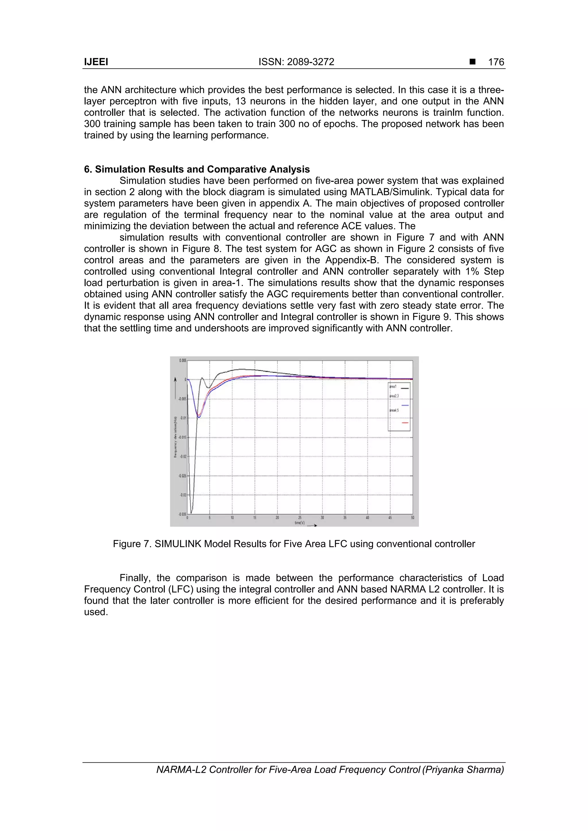
Priyanka Sharma
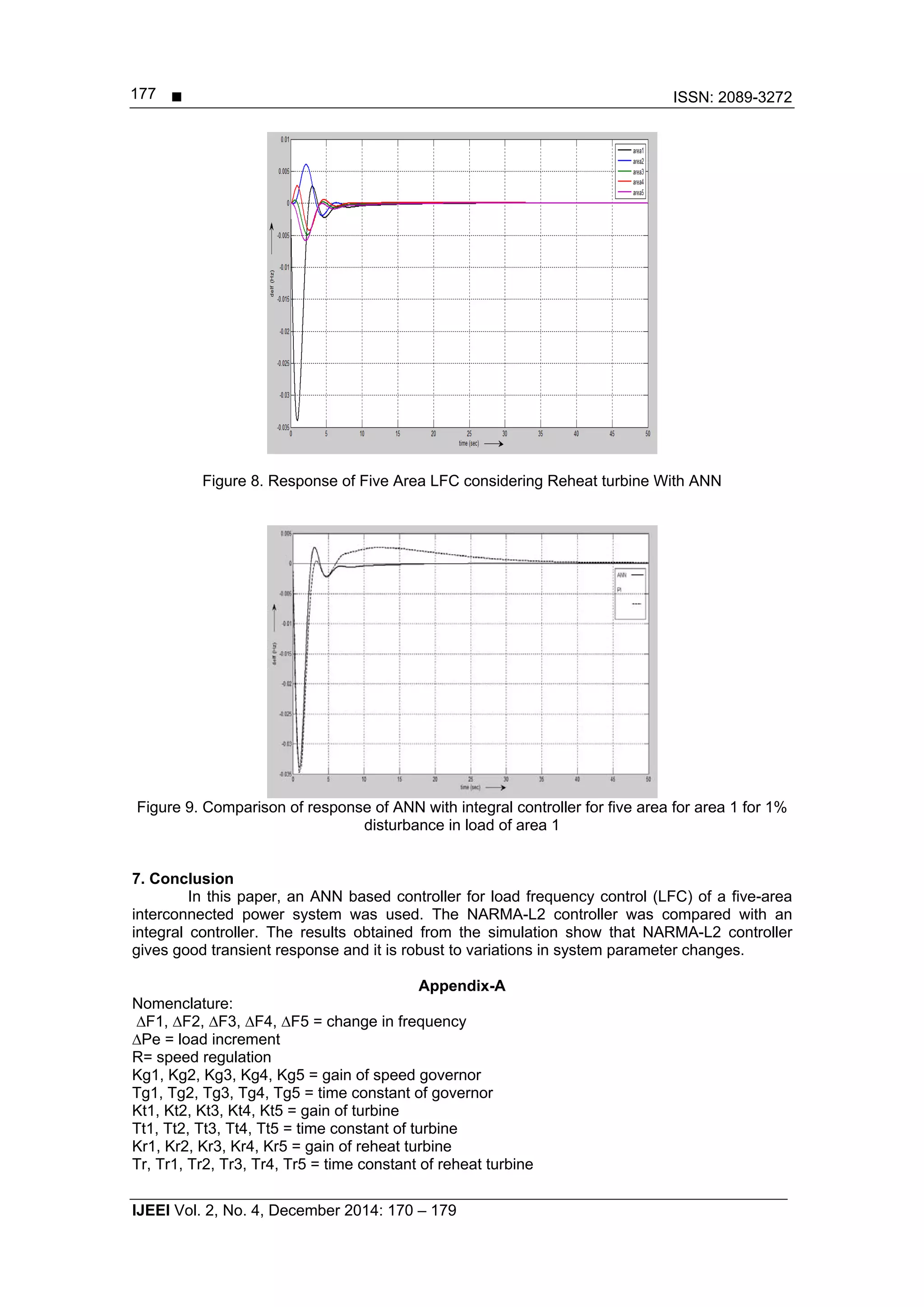
Department of Electrical Engineering, Maharishi Dayanand University, Rohtak, Haryana, India
Email: priyanka.ganaur@gmail.com
Abstract
This paper investigates the load-frequency control (LFC) based on neural network for improving
power system dynamic performance. In this paper an Artificial Neural Network (ANN) based controller is
presented for the Load Frequency Control (LFC) of a five area interconnected power system. The
controller is adaptive and is based on a nonlinear auto regressive moving average (NARMA-L2) algorithm.
The working of the conventional controller and ANN based NARMA L2 controllers is simulated using
MATLAB/SIMULINK package.. The Simulink link results of both the controllers are compared.
Keywords: Area Control Error (ACE), Artificial Neural Network (ANN), Genetic Algorithm (GA), Load
Frequency Control (LFC), Artificial Neural Network (ANN)
1. Introduction
The organizations are responsible for providing electrical power with great reliability,
availability and efficiency. In present time the demand for electrical power and load is not
constant but kept on changing. It becomes necessary to change power generations according
to load perturbations. A power system consists of a number of interconnected subsystems. For
each subsystem it becomes compulsory to fulfill the requirements usually include matching
system generation to system load and the associated system losses and then regulating system
frequency and tie line power exchanges. This is usually known as load frequency control, also
called Automatic Generation Control (AGC) problem and is very important in the operation of
power systems [1, 2]. The main function of AGC is to maintain the real frequency and the
desired power output (megawatt) in the interconnected power system and to control the change
in tie line power between control areas.
To maintain the system at normal operating state different types of controllers based on
classical and modern control theories have been developed [3-5]. The conventional controller
used for Load Frequency Control is integral controller. The integrator gain is set to a level such
that relation between fast transient recovery and low overshoot in the dynamic response of the
overall system can be maintained [6-7]. But the main disadvantage of this type of controller is
slow and does not give desired performance to the designer corresponding to non-linarites in
the generator unit.
In recent years, modern control techniques, especially adaptive control configurations,
are applied to load-frequency control. The applications of artificial neural networks, genetic
algorithms, fuzzy logic and optimal control to LFC have been reported in [8-15]. In the paper,
artificial neural network (ANN) based controller is used, which is an adaptive control
configuration because this controller provides faster and desired control as compared to others.
The beginning of artificial intelligence (AI) techniques leads to many problems. This technology
mainly used systems which are operating nonlinearly over the operating range. ANN has also
been used in frequency controller design for Multi area AGC scheme in deregulated electricity
market. These networks are also applicable for pattern recognition, function approximation, time
series prediction and classification problems for quite some time. .
Nonlinear autoregressive moving average (NARMA) model is an exact representation of
input-output behavior of a finite-dimensional and nonlinear discrete time dynamic plant in
neighborhood of the equilibrium state [16,17]. This non-linearity, its implementation for real time
control systems makes difficult. To overcome computational complexity related to use of this
type of ANN, two classes of NARMA are introduced in [16]: NARMA-L1 and NARMA-L2. The
latter is more convenient to be practically implemented using multilayer neural networks.](https://image.slidesharecdn.com/03123-192-1-pb-171212060946/75/NARMA-L2-Controller-for-Five-Area-Load-Frequency-Control-1-2048.jpg)
![ ISSN: 2089-3272
IJEEI Vol. 2, No. 4, December 2014: 170 – 179
171
2. FIVE-area Load-Frequency Control Model
The configuration of the investigated power system is given in Figure 1. The directions
of power transfer between areas have been considered as follow:
- from area 1 to area 2 - from area 1 to area 3
- from area 1 to area 4 - from area 1 to area 5
- from area 2 to area 3 - from area 2 to area 4
- from area 2 to area 5 - from area 3 to area 4
- from area 3 to area 5 - from area 4 to area 5
Figure 1. Basic Block Diagram of FIVE area interconnected system
A five area interconnected power system [18] is selected and load frequency control of
this system is made primarily by integral controller and then by an ANN controller [19], [20], [21].
The five areas are interconnected to each other by tie-lines. It is seen that each area needs its
system frequency to be controlled [22], [23], [24] to give desired performance. The reason for
using the proposed controller is due to the fact that it firstly adapts to changing operating points
and calculates optimal control commands, it can also perform effectively with nonlinearities and
even if system inputs are temporarily lost or errors are introduced. The main characteristics of
ANN controller is that it continues to function without needing any decision support software in
case of a failure. For comparison, the AGC of considered power system is accomplished using:
(i) Conventional Integral controller
(ii) ANN based NARMA L2 Controller
3. Modelling and Simulation with Conventional Integral Controller
In five area system, five single area systems are interconnected via tie-line. The
interconnection of power systems increases the overall system reliability. In this case if some
generating units in one area fail, the generating units in the other area can compensate to meet
the load demand. The basic block diagram of five area interconnected power system is shown
in Figure 1.
The power transfer through tie line for the model is given by:
0 01 2
, 1 1 2
12
| || |
sin( )tie
V V
P
X
1, 2 = power angles (angle between rotating magnetic flux & rotor) of equivalent machines of
the two areas](https://image.slidesharecdn.com/03123-192-1-pb-171212060946/75/NARMA-L2-Controller-for-Five-Area-Load-Frequency-Control-2-2048.jpg)
![IJEEI ISSN: 2089-3272
NARMA-L2 Controller for Five-Area Load Frequency Control (Priyanka Sharma)
172
Ptie, 1(pu) = T12 (1 - 2)
Where
0 01 2
12 1 2
1 12
| || |
cos( )
r
V V
T
P X
= synchronizing coefficient
Figure 2. Turbine model
A conventional integral controller is used on five area power system model. The integral
controller improves steady state error and allows a transient response with little or no overshoot.
As long as error remains, the integral output will increase and the speed changer position
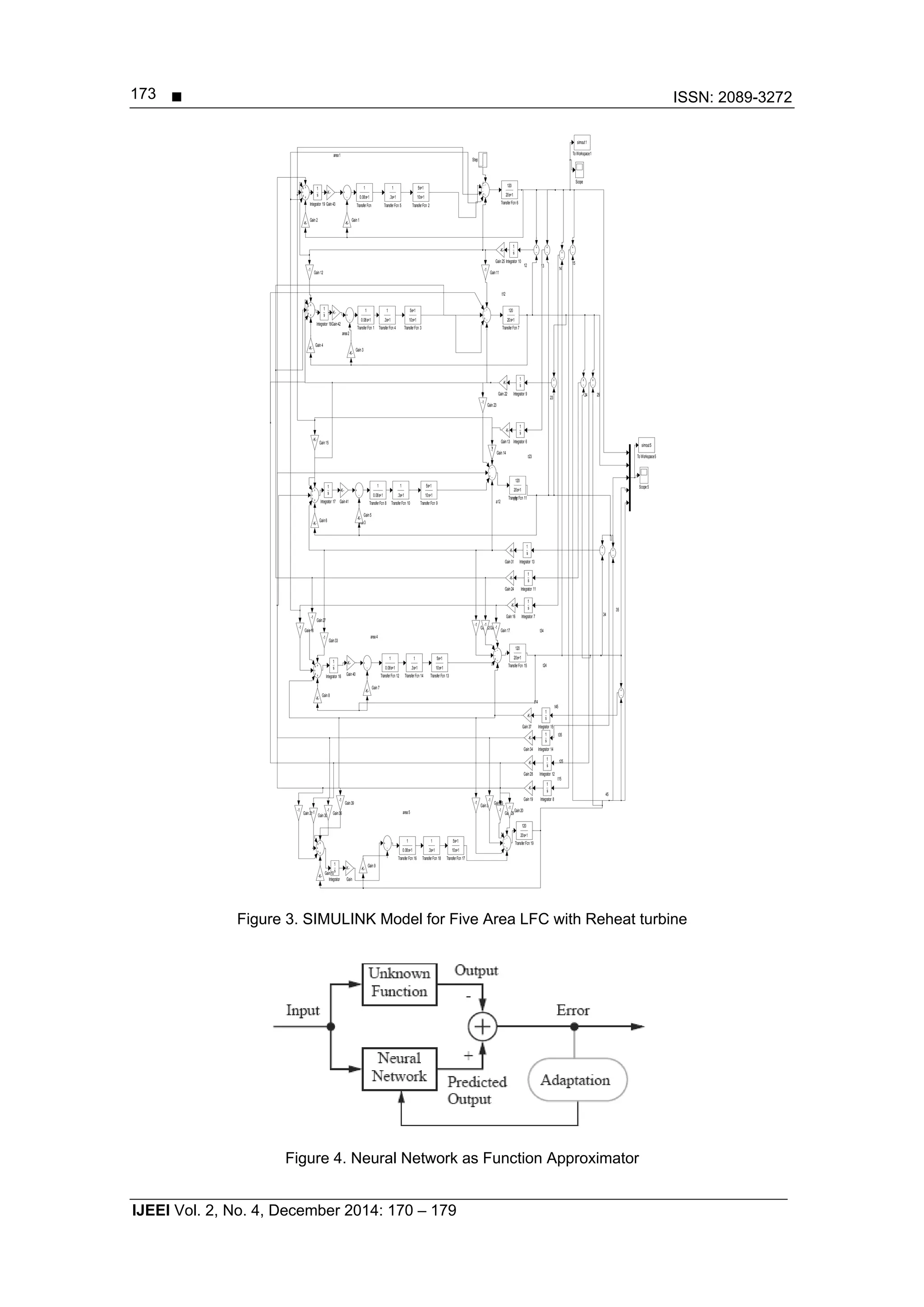
attains a constant value only when the frequency error has reduced to zero. The SIMULINK
model of a five area interconnected power system with reheat turbine using integral controller is
shown in Figure 3.
4. Artificial Neural Network
ANN as the name suggests is information processing system. In this system the
element used for processing the information is called as neurons. The connecting links used for
transmitting signals process an associated weight, which is multiplied along with the incoming
signal (net input) for any typical neural net. The output signal is obtained by applying activation
function to the net input. Neural network architecture-the multilayer perceptron as unknown
function are shown in Figure 4. Parameters of the network are adjusted so that it produces the
same response as the unknown function, if the same input is applied to both systems. The
unknown function could also represent the inverse of a system being controlled; in this case the
neural network can be used to implement the controller [25].](https://image.slidesharecdn.com/03123-192-1-pb-171212060946/75/NARMA-L2-Controller-for-Five-Area-Load-Frequency-Control-3-2048.jpg)
![IJEEI ISSN: 2089-3272
NARMA-L2 Controller for Five-Area Load Frequency Control (Priyanka Sharma)
174
The basis features of neural networks are high computational rates, fault tolerance, self-
decision capability, learning or training, goal –seeking, adaptive features, primitive
computational elements
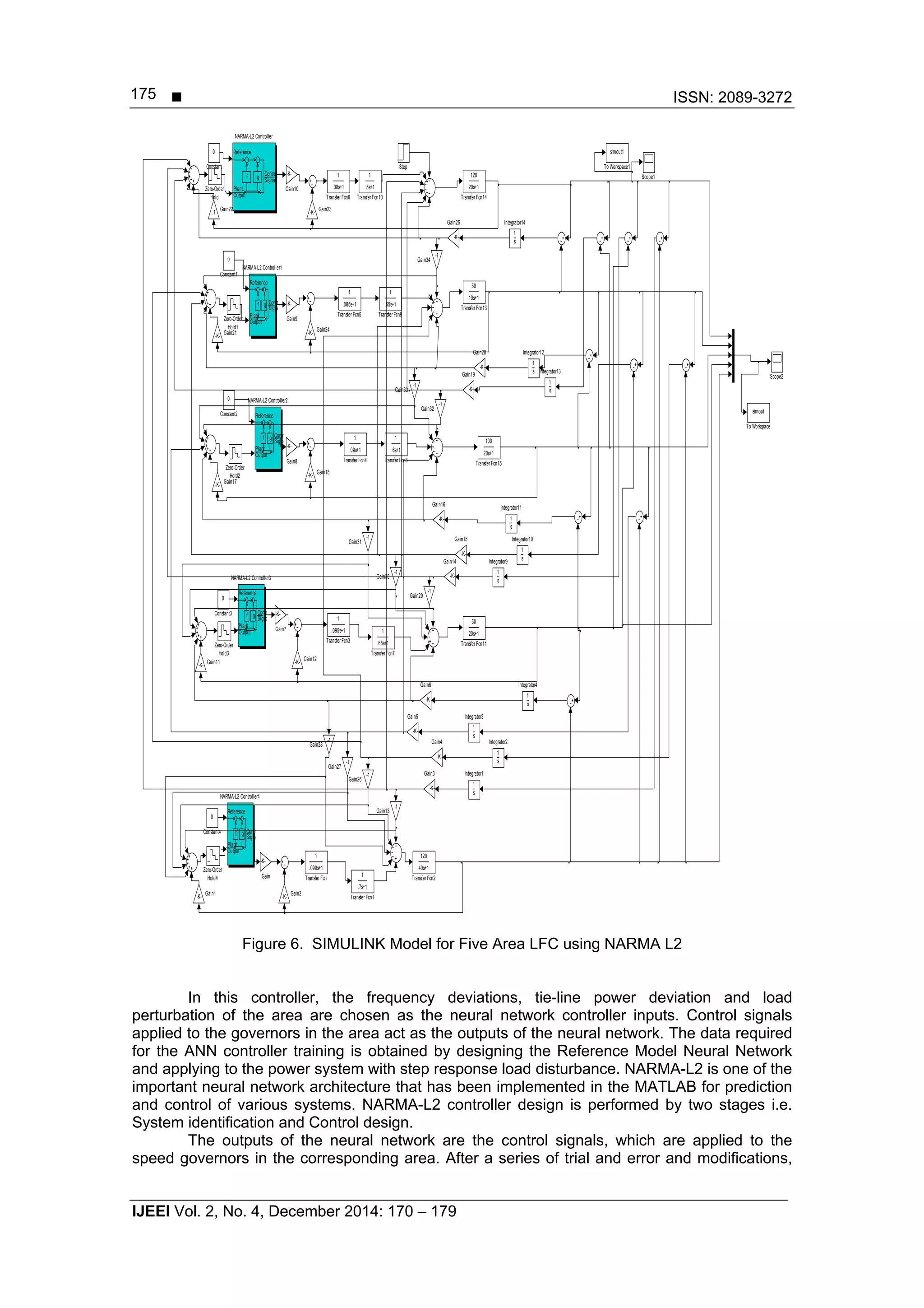
5. NARMA-L2 Control
ANN controller architecture employed here is Nonlinear Auto Regressive Moving
Average(NARMA) model is representation of input output behavior of a finite-dimensional and
nonlinear discrete time dynamic plant in neighborhood of the equilibrium state [27-29]. The non-
linearity property of the ANN controller makes its implementation for real time control systems
difficult. To overcome computational complexity of ANN controllers, two classes of NARMA are
introduced in [27]: NARMA-L1 and NARMA-L2. The NARMAL2 is more convenient to practically
implemented using multi-layer neural networks.
This controller is simply a rearrangement of the neural network plant model, which is
trained offline, in batch form. NARMA L2 controller mainly consists of reference, plant output
and control signal. Computation required for this type of controller is very less. The plant output
is forced to track the reference model output and the effect of controller changes on plant output
is predicted for further calculations. The main quality of this controller is that permits the
updating of controller parameters.](https://image.slidesharecdn.com/03123-192-1-pb-171212060946/75/NARMA-L2-Controller-for-Five-Area-Load-Frequency-Control-5-2048.jpg)
![IJEEI ISSN: 2089-3272
NARMA-L2 Controller for Five-Area Load Frequency Control (Priyanka Sharma)
178
Kps1, Kps2, Kps3, Kps4, Kps5 = gain of generator
Tps1, Tps2, Tps3, Tps4, Tps5 = time constant of generator
Ts = sampling time
∆Pg1, ∆Pg2, ∆Pg3, ∆Pg4, ∆Pg5= governor output
∆Pt1, ∆Pt2, ∆Pt3, ∆Pt4, ∆Pt5 = turbine output
∆Pr1, ∆Pr2, ∆Pr3, ∆Pr4, ∆Pr5 = reheat turbine output
P12, P13, P14, P15, P23, P24, P25, P34, P35, P45 = tie line power
T12, T13, T14, T15, T23, T24, T25, T34, T35, T45 = tie line time constant
Ki = integral controller gain
b1, b2, b3, b4, b5 = bias factor
Appendix-B
Nominal parameters of the system investigated
F=50Hz,
Tg1=Tg2=Tg3=Tg4=Tg5=0.08s,
Tr1=Tr2=Tr3=Tr4=Tr5=10s,
H1=H2 =H3=H4=H5=5,
Tt1=Tt2=Tt3=Tt4=Tt5=0.3s
Kr1=Kr2=Kr3=Kr4=Kr5=0.5Hz/puMW,
Ptiemax=200MW,
Tps1=Tps2=Tps3=Tps4=Tps5=20s,
Kps1=Kps2=Kps3=Kps4=Kps5=120Hz/p.uMW;
T12=0.08674; Ki=0.1,Ts=0.01,
References
[1] Ashmole PH, Battebury DR, Bowdler RK. Power-system model for large frequency
disturbances. Proceedings of the IEEE. 1974; 121(7): 601–8.
[2] Pan CT, CM. An adaptive controller for power system load–frequency control. IEEE
Transactions on Power Systems. 1989; 4(1): 122–8
[3] Anderson PM, Fouad AA. Power system control and stability. Ames, IA: Iowa State University Press,
1977
[4] Debs AS. Modern power systems control and operation. Norwell, MA: Kluwer-Nijhoff Publishers,
1988.
[5] Wood AJ, Wollenberg BF. Power generation, operation and control. New York: Wiley, 1984.
[6] Elgerd OE. Electric energy system theory. New York: McGraw Hill,1982.
[7] Murty PSR. Power system operation and control. New Delhi: Tata McGraw Hill, 1984.
[8] Shayegi H, Shayanfar HA, Malik OP. Robust decentralized neural networks based LFC in a
deregulated power system. Electr Power Syst Res. 2007; 77: 241–51.
[9] Pan CT, Liaw CM. An adaptive control for power system LFC. IEEE Trans Power Syst. 1989; 4(1):
122–8.
[10] Talaq J, Al-basri H. Adaptive fuzzy gain scheduling for LFC. IEEE Trans Power Syst. 1999; 14(1):
145–50.
[11] Kocaarslan _Ilhan, C¸ am Ertug˘ rul. Fuzzy logic controller in interconnected electrical power systems
for load-frequency control. Int J Electr Power Energy Syst. 2005; 27(8): 542–9.
[12] Anand B, Ebenezer Jeyakumar A. Load frequency control with fuzzy logic controller considering non-
linearities and boiler dynamics. ICGST-ACSE J. 2009; 8(III).
[13] Sˇ ijak Tomislav, Kulja Ognjen, Kulja Ljubomir, Tesˇnjak Sejid. Design of fuzzy regulator for power
system secondary load frequency control. In: Proceedings of the 10th Mediterranean conference on
control and automation – MED2002, Lisbon, Portugal, 2002.
[14] C¸ am Ertug˘ rul. Application of fuzzy logic for load frequency control of hydro electrical power plants.
Energy Convers Manage. 2007; 48(4): 1281–8.
[15] C¸ am Ertu rul, Kocaarslan Ihan. Load frequency control in two area power systems using fuzzy logic
controller. Energy Convers Manage. 2005; 46(2): 233–43.
[16] Narendra KS, and S Mukhopadhyay. “Adaptive Control Using Neural Networks and Approximate
Models”. IEEE Trans. Neural Networks. 1997; 8: 475-485.
[17] H Demuth, M Beale, M Hagan. Neural network toolbox user’s guide.
[18] J Nanda S Mishra. "A novel classical controller for automatic generation control in thermal and
hydrothermal Power Electronics”. Drives and Energy Systems (PEDES). 2010; 6.
[19] JA Jaleel, TPI Ahammed. "Simulation of ANN Controller for Automatic Generation Control of
Hydroelectric Power System". TENCON-2008. 2008: 1-4.](https://image.slidesharecdn.com/03123-192-1-pb-171212060946/75/NARMA-L2-Controller-for-Five-Area-Load-Frequency-Control-9-2048.jpg)
![ ISSN: 2089-3272
IJEEI Vol. 2, No. 4, December 2014: 170 – 179
179
[20] IA Chidambaram, R Francis. "Automatic Generation Control of a Two Area Reheat Interconnected
System based on CPS using Fuzzy Neural Network". Emerging Trends in Electricaland Computer
Technology (ICETECT). 2011: 200-205.
[21] Livingstone David. J. Artificial Neural Networks.
[22] CS Chang, Weihui fu. Area Load Frequency Control using Fuzzy Gain scheduling of PI controllers.
Electric Power Systems Research. 1997; 42:145-52.
[23] KP Singh Parmar, S Majhi and DP Kothari. Automatic Generation Control of an Interconnected
Hydrothermal Power System. IEEE Conf. proceedings, INDICON 2010, Kolkata, India.
[24] KP Singh Parmar, S Majhi and DP Kothari. Multi area Load Frequency Control in a Power System
Using Optimal Output Feedback Method. IEEE Conf. proceedings PEDES 2010, New Delhi, India.
[25] S Hykin. “Neural Network”. Mac Miller NY 1994.
[26] DM Vinod Kumar. "Intelligent Controllers for Automatic Generation Control". IEEE transactions. 1999:
557-574.
[27] Narendra KS and S Mukhopadhyay. “Adaptive Control Using Neural Networks and Approximate
Models”. IEEE Trans. Neural Networks. 1997; 8: 475-485.
[28] H Demuth, M Beale, M Hagan. Neural network toolbox user’s guide.
[29] Surya Prakash, SK Sinha. “Application of artificial intelligence in load frequency control of
interconnected power system”. International Journal of Engineering, Science and Technology. 2011;
3(4): 264-275.](https://image.slidesharecdn.com/03123-192-1-pb-171212060946/75/NARMA-L2-Controller-for-Five-Area-Load-Frequency-Control-10-2048.jpg)