The document presents an optimal artificial neural network (ANN) controller for managing load frequency control (LFC) in a four-area interconnected power system, utilizing a feedforward neural network trained via Bayesian regularization backpropagation. This study emphasizes the controller's design based on optimal control theory, aims to address load changes, and compares its effectiveness against traditional PID and NARMA-L2 controllers using MATLAB-Simulink simulations. Results indicate superior accuracy and robustness of the proposed ANN controller in frequency and power management tasks.
![International Journal of Electrical and Computer Engineering (IJECE)
Vol. 12, No. 5, October 2022, pp. 4700~4711
ISSN: 2088-8708, DOI: 10.11591/ijece.v12i5.pp4700-4711 4700
Journal homepage: http://ijece.iaescore.com
An optimal artificial neural network controller for load
frequency control of a four-area interconnected power system
Basavarajappa Sokke Rameshappa, Nagaraj Mudakapla Shadaksharappa
Department of Electrical and Electronics Engineering, Bapuji Institute of Engineering and Technology,
Davanagere Visvesvaraya Technological University, Belagavi, India
Article Info ABSTRACT
Article history:
Received Sep 2, 2021
Revised Mar 11, 2022
Accepted Apr 10, 2022
In this paper, an optimal artificial neural network (ANN) controller for load
frequency control (LFC) of a four-area interconnected power system with
non-linearity is presented. A feed forward neural network with multi-layers
and Bayesian regularization backpropagation (BRB) training function is
used. This controller is designed on the basis of optimal control theory to
overcome the problem of load frequency control as load changes in the
power system. The system comprised of transfer function models of two
thermal units, one nuclear unit and one hydro unit. The controller model is
developed by considering generation rate constraint (GRC) of different units
as a non-linearity. The typical system parameters obtained from IEEE press
power engineering series and EPRI books. The robustness, effectiveness,
and performance of the proposed optimal ANN controller for a step load
change and random load change in the system is simulated through using
MATLAB-Simulink. The time response characteristics are compared with
that obtained from the proportional, integral and derivative (PID) controller
and non-linear autoregressive-moving average (NARMA-L2) controller. The
results show that the algorithm developed for proposed controller has a
superiority in accuracy as compared to other two controllers.
Keywords:
Interconnected power system
Load frequency control
NARMA-L2 controller
Optimal ANN controller
PID controller
This is an open access article under the CC BY-SA license.
Corresponding Author:
Basavarajappa Sokke Rameshappa
Department of Electrical and Electronics Engineering, Bapuji Institute of Engineering and Technology
Shamanur Road, Davanagere-577004, Karnataka, India
Email: basavarajsr@gmail.com
1. INTRODUCTION
Automatic load frequency control is the main area of concern in the operation of an interconnected
power system. As load on the system changes, the frequency changes. In order to balance the megawatt
(MW) generation with load demand, it is necessary to control the synchronous generators power output and
frequency. This control is automatic, as it maintains the frequency at base value and power flows via tie-lines
within scheduled values for a perturbation in the load [1]–[3]. The load frequency control monitors the area
control error (ACE), which is the net real power interchange between the control areas plus the frequency
deviation multiplied with a frequency bias. To reduce ACE, closer to zero, change the position of speed
changer of the generator governors within the control area by means of load frequency control (LFC).
In the design of load frequency controllers, conventional control techniques have been developed,
which gives slower responses. The developments in advanced technology, artificial intelligent (AI) based
techniques such as neural networks, fuzzy logic, genetic algorithm (GA) and particle swarm optimization
(PSO) have been using and these techniques overcome the disadvantages of conventional controllers and
increase the speed of response. When the load changes suddenly, the primary automatic load frequency
control can be obtained by the action of speed governor in the prime movers. A supplementary or secondary](https://image.slidesharecdn.com/18157076107026749em11mar222sepn-220909025459-b3886cab/75/An-optimal-artificial-neural-network-controller-for-load-frequency-control-of-a-four-area-interconnected-power-system-1-2048.jpg)
![Int J Elec & Comp Eng ISSN: 2088-8708
An optimal artificial neural network controller for load frequency … (Basavarajappa Sokke Rameshappa)
4701
automatic load frequency control action is used in the proposed system to bring the change in frequency and
change in tie-line power to zero with the help of advanced controllers. The past studies in the literature
explain the LFC problem with proportional-integral-derivative (PID) and fuzzy logic controllers, but less
with optimal artificial neural network (ANN) controller and nonlinearity.
Prasad and Ansari [4], employed a three-layer ANN observer-based control strategy used in a two
similar area interconnected power system with generation rate constraint (GRC) and governor dead band
(GDB). This system is simulated for random unmatched disturbance estimation and its rejection. Qian and
Fan [5], implemented a three-layer radial basis function (RBF) neural network for load frequency control of a
two-area power system with GRC and wind turbine model. The control scheme is designed on the basis of
terminal sliding mode control. Bhatia et al. [6] proposed a three-layer neural network-based NARMA-L2
controller for a three similar area power system with GRC. Only frequency deviation is discussed. Chettibi
et al. [7] proposed and implemented a technique for forecast of grid voltage frequency in short time based on
ANN models and deep recurrent neural networks. This can be used in an advanced control scheme and
monitoring distributed generators for frequency and voltage variations. The performance of these networks
was assessed in terms of root mean square error (RMSE) that was lies between 0.002 Hz and 0.01 Hz for
sapling interval of 0.1 s and 1 s respectively.
Alzaareer et al. [8] proposed an ANN based NARMA-L2 controller model for a three-area
interconnected system without GRC. This controller is compared with PI and PID controller for load
frequency control in the system. Prakash and Sinha [9], proposed a hybrid neuro fuzzy (HNF) controller in a
four–area power system without GRC. This controller performance is compared with fuzzy logic, three-layer
ANN and PID controllers for 1% change in load. Peak overshoot and settling time values of -0.055 pu
(-2.75 Hz) and 40 s respectively, obtained with ANN controller. Kumari et al. [10], proposed an ANN-PID
control technique for a two area non-reheat thermal plant power system without GRC. The controller
performance is tested with 10% step load perturbation and different error values are measured. Prakash and
Sinha [11], proposed an ANN and adaptive neuro fuzzy inference system (ANFIS) for a six-area power
system composed of hydro, thermal, gas, diesel, and nuclear plants without GRC. The controller performance
is tested with 1% step load perturbation. Mucka et al. [12], employed a three-layer neural network-based
NARMA-L2 controller for a four-area power system without GRC. The system is simulated with 2% change
in load at frequency 50 Hz and its response has more settling time and undershoot.
The above research work [4]–[7], employs ANN based controller for two-area and three-area
interconnected power system with GRC. Only two input variables and first order governor-turbine transfer
function models are considered and the work [8]–[12], even though propose ANN based controllers with
Levenberg-Marquardt learning function but does not provide information on the number of neurons in the
hidden layer(s) and considered only first order non-reheat turbines without GRC. Hence, the present work
proposes an optimal ANN controller with BRB training function and is designed based on state space model
for load frequency control in a four-area power system comprises reheat tandem compound turbines with
GRC and IEEE standard parameters are chosen within the operating constraints of system components.
2. MODELLING OF THE SYSTEM
The main components of each area are governor, turbine, generator, and load. The dynamic models
of governors, tandem compound steam turbines and hydro turbines were presented in [13], [14]. For thermal,
nuclear, and hydro power plants, the transfer function models of a governor or hydraulic valve actuator are
obtained from the basic Watt’s governor operation. The thermal plant governor and turbine block diagram
with fraction of power generated by high pressure (HP), intermediate pressure (IP), and low pressure (LP)
sections is shown in Figure 1. Figure 2 shows the block diagram of nuclear plant governor and turbine with
fraction of power generated by very high pressure (VHP), high pressure (HP), and low pressure (LP)
sections. Figure 3 shows the block diagram of hydro plant governor and turbine.
The generation rate constraint is the limitation on the rate of change in the real power generation due
to physical limitations of turbine. The existence of GRC [5], [7], [15] has an adverse effect on system
stability. It should be considered for LFC problem as a non-linear model shown in Figure 4. The GRC values
are taken into account by adding limiters to the turbines. The GRC values for thermal and nuclear plants are
±0.005 𝑝𝑢. 𝑀𝑊. 𝑠−1
and that for hydro plant is +0.045 𝑝𝑢. 𝑀𝑊. 𝑠−1
and −0.06 𝑝𝑢. 𝑀𝑊. 𝑠−1
. The transfer
function model of synchronous generator and load is obtained by rotor dynamics, swing equation and overall
frequency dependent characteristic of a composite load. Synchronous generator-load transfer function model
[1], [2] in standard first order form is obtained as (1).
𝐺𝑆𝐿(𝑠) =
1
2 𝑠 𝐻𝑖+𝐷𝑖
=
𝐾𝑝𝑠,1
1+𝑠 𝑇𝑝𝑠,1
𝑓𝑜𝑟 𝑖 = 1,2,3,4 (1)](https://image.slidesharecdn.com/18157076107026749em11mar222sepn-220909025459-b3886cab/75/An-optimal-artificial-neural-network-controller-for-load-frequency-control-of-a-four-area-interconnected-power-system-2-2048.jpg)
![ ISSN: 2088-8708
Int J Elec & Comp Eng, Vol. 12, No. 5, October 2022: 4700-4711
4702
Figure 1. Thermal plant governor and turbine model
Figure 2. Nuclear plant governor and turbine model
Figure 3. Hydro plant governor and turbine model
Figure 4. Generation rate constraint model
The output of generator-load model is the change in frequency or the frequency deviation ∆𝑓𝑖(𝑠)
due to change in load ∆𝑃𝐿𝑖(𝑠). In normal operation, the change in tie-line power is obtained from
synchronizing torque coefficient (T) using (2). ACE [9] is the input signal to controller for each power
system area and is calculated using (3).
∆𝑃𝑖𝑗(𝑠) =
2𝜋𝑇
𝑠
(∆𝑓𝑖(𝑠) − ∆𝑓𝑗(𝑠)) 𝑓𝑜𝑟 𝑖 = 1,2,3,4 (2)
𝐴𝐶𝐸𝑖 = ∆𝑃𝑖𝑗 + 𝐵𝑖∆𝑓𝑖 (3)
The objective function (OF) determines the system dynamics and satisfy criterion such as fast response with
minimized undershoot and steady state error. Thus, integral of time weighted absolute error (ITAE) is used as
OF [15] and is calculated as (4).
𝐼𝑇𝐴𝐸𝑖 = ∫ 𝑡|∆𝑃𝑖𝑗 + 𝐵𝑖∆𝑓𝑖|
𝑡𝑚𝑎𝑥
0
𝑑𝑡 (4)
By connecting the block diagrams of governor, turbine, generation rate constraint, generator and load models
of respective areas and interconnecting these areas via tie-line model gives the complete block diagram of a
four-area interconnected power system as shown in Figure 5.](https://image.slidesharecdn.com/18157076107026749em11mar222sepn-220909025459-b3886cab/75/An-optimal-artificial-neural-network-controller-for-load-frequency-control-of-a-four-area-interconnected-power-system-3-2048.jpg)
![Int J Elec & Comp Eng ISSN: 2088-8708
An optimal artificial neural network controller for load frequency … (Basavarajappa Sokke Rameshappa)
4703
Figure 5. Four area interconnected power system
3. PID AND NARMA-L2 CONTROLLERS
3.1. PID controller
The PID controllers are conventional controllers used when the system requires improvement under
steady-state and transient conditions. These controllers design is simple and inexpensive. The Ziegler-
Nichols method proposed in [16], [17], is employed to determine the tuned gain values of proportional (𝐾𝑝),
integral (𝐾𝑖) and derivative (𝐾𝑑).
3.2. NARMA-L2 controller
The non-linear autoregressive moving average controller is the most effective in the non-linear
control systems. It is referred to as NARMA-L2 control when the plant model can be approximated by a
particular form [18]–[21]. The dynamic responses of the area frequency and tie-line power flows are obtained
using this controller in the power systems [22]. Its main function is to transform non-linear system dynamics
into linear dynamics by cancelling the non-linearities.
4. RESEARCH METHOD-OPTIMAL ANN CONTROLLER
In the design of load frequency optimal controller, an artificial neural network (ANN) is to be
trained. The flow chart of neural network training process is shown in Figure 6. The training process is
divided into three main sections, which are pre-training steps, training the network, and post-training
analysis.](https://image.slidesharecdn.com/18157076107026749em11mar222sepn-220909025459-b3886cab/75/An-optimal-artificial-neural-network-controller-for-load-frequency-control-of-a-four-area-interconnected-power-system-4-2048.jpg)
![ ISSN: 2088-8708
Int J Elec & Comp Eng, Vol. 12, No. 5, October 2022: 4700-4711
4704
Figure 6. Flow chart of neural network training process
4.1. Data collection and preprocessing
The optimal controller is designed for the power system using state space model [23] with 32 state
variables and 4 control output variables. The aim of this controller is to obtain a control law 𝑢(𝑥, 𝑡) for
minimizing the performance index. Formulation of the state space model is achieved by writing differential
equations [13], [24] describing each individual block of four area power system in terms of state variables.
These variables are output of various blocks represent the change in mechanical power, electrical
power and frequency and are defined as:
- State variables:
𝑥1 = ∆𝑓1, 𝑥2 = ∆𝑃𝑚1, 𝑥3 = ∆𝑃𝐶𝑂1, 𝑥4 = ∆𝑃𝑅𝐻1, 𝑥5 = ∆𝐶𝐻1, 𝑥6 = ∆𝑃𝑉1, 𝑥7 = ∆𝑓2, 𝑥8 = ∆𝑃𝑚2,
𝑥9 = ∆𝑃𝐶𝑂2, 𝑥10 = ∆𝑃𝑅2, 𝑥11 = ∆𝑃𝑅1, 𝑥12 = ∆𝑃𝐶𝐻2, 𝑥13 = ∆𝑃𝑣2, 𝑥14 = ∆𝑓3, 𝑥15 = ∆𝑃𝑚3,
𝑥16 = ∆𝑃𝐶𝑂3, 𝑥17 = ∆𝑃𝑅𝐻3, 𝑥18 = ∆𝑃𝐶𝐻3, 𝑥19 = ∆𝑃𝑉3, 𝑥20 = ∆𝑓4, 𝑥21 = ∆𝑃𝑚4, 𝑥22 = ∆𝑃𝐻𝑇,
𝑥23 = ∆𝑃𝐻𝑅, 𝑥24 = ∆𝑃𝐻𝐺, 𝑥25 = ∆𝑃12 + ∆𝑃13 + ∆𝑃14, 𝑥26 = ∆𝑃22 + ∆𝑃23 + ∆𝑃24,
𝑥27 = ∆𝑃31 + ∆𝑃32 + ∆𝑃34, 𝑥28 = ∆𝑃41 + ∆𝑃42 + ∆𝑃43, 𝑥29 = ∫ 𝐴𝐶𝐸1 𝑑𝑡, 𝑥30 = ∫ 𝐴𝐶𝐸2 𝑑𝑡
𝑥31 = ∫ 𝐴𝐶𝐸3 𝑑𝑡, 𝑥32 = ∫ 𝐴𝐶𝐸4 𝑑𝑡
Control inputs: 𝑢1, 𝑢2, 𝑢3 and 𝑢4, disturbance inputs: 𝑑1 = ∆𝑃𝐿1, 𝑑2 = ∆𝑃𝐿2, 𝑑3 = ∆𝑃𝐿3 and 𝑑4 = ∆𝑃𝐿4
- State equations:
For block 1: 𝑥̇1 = −
1
𝑇𝑝𝑠1
𝑥1 +
𝐾𝑝𝑠1
𝑇𝑝𝑠1
𝑥2 −
𝐾𝑝𝑠1
𝑇𝑝𝑠1
𝑥25 −
𝐾𝑝𝑠1
𝑇𝑝𝑠1
𝑑1 (5)
For block 2: 𝑥̇2 = 𝑥3 (6)
For block 3: 𝑥̇3 = −
1
𝑇𝑡𝑐
𝑥3 + (
𝐾𝑡𝑙
𝑇𝑡𝑐
+
𝐾𝑡𝑖
𝑇𝑡𝑐
−
𝐾𝑡𝑖
𝑇𝑡𝑟
) 𝑥4 + (
𝐾𝑡ℎ
𝑇𝑡𝑐
+
𝐾𝑡𝑖
𝑇𝑡𝑟
−
𝐾𝑡ℎ
𝑇𝑡𝑡
) 𝑥5 +
𝐾𝑡ℎ
𝑇𝑡𝑡
𝑥6
𝑥̇4 = −
1
𝑇𝑡𝑟
𝑥4 +
1
𝑇𝑡𝑟
𝑥5 and 𝑥̇5 = −
1
𝑇𝑡𝑡
𝑥5 +
1
𝑇𝑡𝑡
𝑥6 (7)
For block 4: 𝑥̇6 = −
1
𝑅1 𝑇𝑡𝑔
𝑥1 −
1
𝑇𝑡𝑔
𝑥6 +
1
𝑇𝑡𝑔
𝑢1 (8)
For block 5: 𝑥̇7 = −
1
𝑇𝑝𝑠2
𝑥7 +
𝐾𝑝𝑠2
𝑇𝑝𝑠2
𝑥8 −
𝐾𝑝𝑠2
𝑇𝑝𝑠2
𝑥26 −
𝐾𝑝𝑠2
𝑇𝑝𝑠2
𝑑2 (9)
For block 6: 𝑥̇8 = 𝑥9 (10)](https://image.slidesharecdn.com/18157076107026749em11mar222sepn-220909025459-b3886cab/75/An-optimal-artificial-neural-network-controller-for-load-frequency-control-of-a-four-area-interconnected-power-system-5-2048.jpg)
![Int J Elec & Comp Eng ISSN: 2088-8708
An optimal artificial neural network controller for load frequency … (Basavarajappa Sokke Rameshappa)
4705
For block 7: 𝑥̇9 = −
1
𝑇𝑛𝑐
𝑥9 +
𝐾𝑛𝑙
𝑇𝑛𝑐
𝑥10 + (
𝐾𝑛ℎ
𝑇𝑛𝑐
−
𝐾𝑛ℎ
𝑇𝑛𝑟1
) 𝑥11 + (
𝐾𝑛𝑣
𝑇𝑛𝑐
−
𝐾𝑛𝑣
𝑇𝑛𝑡
+
𝐾𝑛ℎ
𝑇𝑛𝑟1
) 𝑥12 +
𝐾𝑛𝑣
𝑇𝑛𝑡
𝑥13
𝑥̇10 = −
1
𝑇𝑛𝑟2
𝑥10 +
1
𝑇𝑛𝑟2
𝑥11, 𝑥̇11 = −
1
𝑇𝑛𝑟1
𝑥11 +
1
𝑇𝑛𝑟1
𝑥12 and
𝑥̇12 = −
1
𝑇𝑛𝑡
𝑥12 +
1
𝑇𝑛𝑡
𝑥13 (11)
For block 8: 𝑥̇13 = −
1
𝑅2 𝑇𝑛𝑔
𝑥7 −
1
𝑇𝑛𝑔
𝑥13 +
1
𝑇𝑛𝑔
𝑢2 (12)
For block 9: 𝑥̇14 = −
1
𝑇𝑝𝑠3
𝑥14 +
𝐾𝑝𝑠3
𝑇𝑝𝑠3
𝑥15 −
𝐾𝑝𝑠3
𝑇𝑝𝑠3
𝑥27 −
𝐾𝑝𝑠3
𝑇𝑝𝑠3
𝑑3 (13)
For block 10: 𝑥15
̇ = 𝑥16 (14)
For block 11: 𝑥̇16 = −
1
𝑇𝑡𝑐
𝑥16 + (
𝐾𝑡𝑙
𝑇𝑡𝑐
+
𝐾𝑡𝑖
𝑇𝑡𝑐
−
𝐾𝑡𝑖
𝑇𝑡𝑟
) 𝑥17 + (
𝐾𝑡ℎ
𝑇𝑡𝑐
+
𝐾𝑡𝑖
𝑇𝑡𝑟
−
𝐾𝑡ℎ
𝑇𝑡𝑡
) 𝑥18 +
𝐾𝑡ℎ
𝑇𝑡𝑡
𝑥6
𝑥̇17 = −
1
𝑇𝑡𝑟
𝑥17 +
1
𝑇𝑡𝑟
𝑥18 and 𝑥̇18 = −
1
𝑇𝑡𝑡
𝑥18 +
1
𝑇𝑡𝑡
𝑥19 (15)
For block 12: 𝑥̇19 = −
1
𝑅3 𝑇𝑡𝑔
𝑥14 −
1
𝑇𝑡𝑔
𝑥19 +
1
𝑇𝑡𝑔
𝑢3 (16)
For block 13: 𝑥̇20 = −
1
𝑇𝑝𝑠4
𝑥20 +
𝐾𝑝𝑠4
𝑇𝑝𝑠4
𝑥21 −
𝐾𝑝𝑠4
𝑇𝑝𝑠4
𝑥28 −
𝐾𝑝𝑠4
𝑇𝑝𝑠4
𝑑4 (17)
For block 14: 𝑥21
̇ = 𝑥22 (18)
For block 15: 𝑥̇22 = − (
1
0.5 𝑅4 𝑇ℎ𝑔(1+
𝑅ℎ𝑡
𝑅ℎ
)
) 𝑥20 −
1
0.5 𝑇ℎ𝑤
𝑥22 +
(
1
0.5 𝑇ℎ𝑤
+
1
0.5 𝑇ℎ𝑟(1+
𝑅ℎ𝑡
𝑅ℎ
)
) 𝑥23 − (
1−
𝑇ℎ𝑟
𝑇ℎ𝑔
0.5 𝑇ℎ𝑟(1+
𝑅ℎ𝑡
𝑅ℎ
)
) 𝑥24 − (
1
0.5 𝑇ℎ𝑔(1+
𝑅ℎ𝑡
𝑅ℎ
)
) 𝑢4 (19)
For block 16: 𝑥̇23 = − (
1
𝑅4 𝑇ℎ𝑔(1+
𝑅ℎ𝑡
𝑅ℎ
)
) 𝑥20 − (
1
𝑇ℎ𝑟(1+
𝑅ℎ𝑡
𝑅ℎ
)
) 𝑥23 +
(
1 −
𝑇ℎ𝑟
𝑇ℎ𝑔
𝑇ℎ𝑟 (1 +
𝑅ℎ𝑡
𝑅ℎ
)
) 𝑥24 + (
1
𝑇ℎ𝑔 (1 +
𝑅ℎ𝑡
𝑅ℎ
)
) 𝑢4
𝑥̇24 = −
1
𝑅4 𝑇ℎ𝑔
𝑥20 −
1
𝑇ℎ𝑔
𝑥24 +
1
𝑇ℎ𝑔
𝑢4 (20)
For tie-lines: 𝑥̇25 = 2𝜋 𝑇(3𝑥1 − 𝑥7 − 𝑥14 − 𝑥20), 𝑥̇26 = 2𝜋 𝑇(3𝑥7 − 𝑥1 − 𝑥14 − 𝑥20)
𝑥̇27 = 2𝜋 𝑇(3𝑥14 − 𝑥1 − 𝑥7 − 𝑥20), 𝑥̇28 = 2𝜋 𝑇(3𝑥20 − 𝑥1 − 𝑥7 − 𝑥14) (21)
For controller inputs: 𝑥̇29 = 𝐵1𝑥1 + 𝑥25, 𝑥̇30 = 𝐵2𝑥7 + 𝑥26, 𝑥̇31 = 𝐵3𝑥14 + 𝑥27,
𝑥̇32 = 𝐵4𝑥20 + 𝑥28 (22)
Then, the state equation in matrix form:
𝑥̇ = 𝐴𝑥 + 𝐵𝑢 + 𝐹𝑑 (23)
Output equation:
𝑦 = 𝐶𝑥 (24)
where the matrix A (32×32) is a coefficient matrix of all the state variables, the matrix B (32x4) is a
coefficient matrix of all the control variables, the matrix F (32x4) is a coefficient matrix of all the disturbance
variables, the matrix C (1x32) is a coefficient matrix of output variables, 𝑥 = [𝑥1, 𝑥2, … , 𝑥32]𝑇
= state vector,
𝑢 = [𝑢1 … 𝑢4]𝑇
= control vector and 𝑑 = [𝑑1 … 𝑑4]𝑇
=disturbance vector.](https://image.slidesharecdn.com/18157076107026749em11mar222sepn-220909025459-b3886cab/75/An-optimal-artificial-neural-network-controller-for-load-frequency-control-of-a-four-area-interconnected-power-system-6-2048.jpg)
![ ISSN: 2088-8708
Int J Elec & Comp Eng, Vol. 12, No. 5, October 2022: 4700-4711
4706
The optimal control inputs vector, 𝑢 = −𝐾𝑥 is obtained by a linear combination of all states, where
K is the feedback gain matrix. MATLAB code is used to obtain the matrix K by solving of the reduced matrix
Riccati equation [6], [9], [20] given by (25):
𝐴𝑇
𝑆 + 𝑆𝐴 − 𝑆𝐵[𝑅−1
𝐵𝑇
𝑆] + 𝑄 = 0 (25)
where 𝑅−1
𝐵𝑇
𝑆 = 𝐾 and matrix S is a real, positive definite and symmetric. The matrices Q and R are
determined on the basis of three considerations: the excursions of 𝐴𝐶𝐸′
𝑠, ∫ 𝐴𝐶𝐸 𝑠 𝑑𝑡 and control inputs
𝑢1 … 𝑢4 about steady values are minimized. These can be recognized as symmetric matrices to minimize
performance index in quadratic form, given by (26) and (27).
𝑃𝐼 =
1
2
∫ (𝑥𝑇
𝑄 𝑥 + 𝑥𝑇
𝑅 𝑢)
∞
0
𝑑𝑡 (26)
𝑃𝐼 =
1
2
∫ [
(𝐵1𝑥1)2
+ 2𝐵1𝑥1𝑥25 + (𝑥25)2
+ (𝐵2𝑥7)2
+ 2𝐵2𝑥7𝑥26 + (𝑥26)2
+ (𝐵3𝑥14)2
+2𝐵3𝑥14𝑥27 + (𝑥27)2
+ (𝐵4𝑥20)2
+ 2𝐵4𝑥20𝑥28 + (𝑥28)2
+ (𝑥29)2
+
(𝑥30)2
+ (𝑥31)2
+ (𝑥32)2
+ (𝑢1)2
+ (𝑢2)2
+ (𝑢3)2
+ (𝑢4)2
]
∞
0
𝑑𝑡 (27)
The discretized system state equations and optimal control inputs vector are used to collect/generate
the training data for different values of step load change. Since the time of study and sampling have been
chosen as 90 s and 0.005 s respectively, a total of 9000 samples are collected for each variable for a step load
change simultaneously in all the four areas. All such variables form one data set, comprises of 40 variables
(𝑥1, 𝑥2, … , 𝑥32, 𝑑1 … 𝑑4, 𝑢1 … 𝑢4 ). Two data sets for each load disturbances have been collected.
4.2. Selecting the neural network architecture
A multilayer feedforward neural network architecture [25] shown in Figure 7 is employed for LFC
in a non-linear four-area interconnected power system. The input scalar vector p is represented by a vertical
bar with R inputs. There are 36 input nodes (R=36) corresponding to two input parameters which are 32 input
nodes, each corresponding to 32 state variables 𝑥1, 𝑥2, … , 𝑥32, and another 4 input nodes for load disturbances
or perturbations (𝑑1 … 𝑑4) in the system. The two hidden layers with hyperbolic tangent sigmoid transfer
function is used with S neurons to verify the dependency of state variables with the load perturbations and the
repeatability of convergence. Hidden layer 1 has 𝑆1
= 20 neurons, hidden layer 2 has 𝑆2
= 10 neurons, and
the output layer has 𝑆3
= 4 neurons with linear transfer function are used in the network. The outputs of
hidden layers 1 and 2 are the inputs for hidden layer 2 and output layer respectively. The vectors
𝑛1
, 𝑛2
and 𝑎3
represent the net inputs, and 𝑎1
, 𝑎2
𝑎𝑛𝑑 𝑎3
represent the outputs of hidden layers 1, 2 and
output layer, respectively. For hyperbolic tangent sigmoid transfer function, input/output relations are given
by (28).
𝑎1
=
𝑒𝑛1
−𝑒−𝑛1
𝑒𝑛1
+𝑒−𝑛1 𝑎𝑛𝑑 𝑎2
=
𝑒𝑛2
−𝑒−𝑛2
𝑒𝑛2
+𝑒−𝑛2 (28)
Figure 7. Neural network architecture
For linear transfer function, input/output relation is given by, 𝑎3
= 𝑛3
(29)
The outputs of hidden layer 1: =𝑎1
= tan 𝑠𝑖𝑔(𝑊1
𝑝𝑥𝑏1) (30)
The outputs of hidden layer 2: 𝑎2
= tan 𝑠𝑖𝑔(𝑊2
𝑎1
𝑥𝑏2) (31)](https://image.slidesharecdn.com/18157076107026749em11mar222sepn-220909025459-b3886cab/75/An-optimal-artificial-neural-network-controller-for-load-frequency-control-of-a-four-area-interconnected-power-system-7-2048.jpg)
![Int J Elec & Comp Eng ISSN: 2088-8708
An optimal artificial neural network controller for load frequency … (Basavarajappa Sokke Rameshappa)
4707
The outputs of output layer: 𝑎3
= 𝑝𝑢𝑟𝑒𝑙𝑖𝑛(𝑊3
𝑎2
𝑥𝑏3
) (32)
where, 𝑊1
, 𝑊2
𝑎𝑛𝑑 𝑊3
represent the weight matrices and 𝑏1
, 𝑏2
𝑎𝑛𝑑 𝑏3
represent bias vectors of hidden
layers 1, 2 and output layer respectively. The output of network 𝑎3
is a (4×1) vector represents the
target/control signals (𝑢1 … 𝑢4) given to power system corresponding to disturbances (𝑑1 … 𝑑4).
4.3. Neural network training
The network training is based on the data collected from the optimal controller for different
perturbations or step load changes. As the inputs are applied to the network, the outputs are compared to the
target values, and the supervised learning rule is used. Before network training, initialize the weights and
biases using the method of Widrow and Nguyen. In this method, set row i of 𝑊1
, 𝑊1
𝑖 , to have a random
direction and a magnitude of | 𝑊1
𝑖 | = 0.7(𝑆1)
1
𝑅
⁄
and set 𝑏𝑖 to a uniform random value between −| 𝑊1
𝑖 |
and | 𝑊1
𝑖 |. Then, Bayesian regularization backpropagation is used to train the network for 100 epochs
because it is very effective algorithm for training multilayer networks and generalized without the need for
the validation data set. According to Levenberg-Marquardt optimization, weights and bias values are
updated, as it minimizes a combination of squared errors and weights. The performance or mean squared
error (MSE) goal is set to a very low value of 1 × 10⁻¹⁰
. Marquardt adjustment parameter and minimum
performance gradient are 0.005 and 1 × 10⁻⁷
respectively. The training is carried out till the completion of
100 epochs or MSE reaches the desired limit. The network was trained with different number of neurons in
the hidden layers. The best MSE value (9.417 × 10⁻¹¹) is obtained at epoch 45, as shown in the Figure 8.
This algorithm computes the effective number of parameters (𝛾 = 220) that are being used by the network.
The values of MSE and 𝛾 indicate that the network with 𝑆1
= 20 and 𝑆2
= 10 is satisfactory.
Figure 8. Neural network training error curve
5. RESULTS AND DISCUSSION
The parameter values of system components are given in Table 1 at base frequency of 50 Hz. The
PID controller is tuned by Z-N method and its parameters are shown in Table 2. MATLAB-Simulink is used
to perform the simulation of a four-area interconnected power system with three types of controllers. Each of
the parameters obtained from the range given in IEEE press power engineering series and EPRI books [26],
[27] based on the design of the electrical components for best performance.
Table 1. Power system parameter values
Parameters 𝑃𝑟 𝑃𝐿 𝑃𝑡𝑖𝑒 𝑓0 𝑇𝑡𝑖𝑒 𝛿 R
All Areas 2000 MW 1000 MW 200 MW 50 Hz 0.0866 30° 2.5 Hz/pu MW
Thermal
Plant
𝑇𝑡𝑔 𝑇𝑡𝑡 𝑇𝑡𝑟 𝑇𝑡𝑐 𝐾𝑡ℎ 𝐾𝑡𝑙 𝐾𝑡𝑖 D B H 𝐾𝑝𝑠 𝑇𝑝𝑠
0.2s 0.3 s 7 s 0.4s 0.3 0.4 0.3 0.01 0.41 5 100 20s
Nuclear
Plant
𝑇𝑛𝑔 𝑇𝑛𝑡 𝑇𝑛𝑟1 𝑇𝑛𝑟2 𝑇𝑛𝑐 𝐾𝑛𝑣 𝐾𝑛𝑙 𝐾𝑛ℎ - - - -
0.2 s 0.3 s 7 s 7 s 0.4 s 0.22 0.56 0.22 0.01 0.41 5 100 20s
Hydro
Plant
𝑇ℎ𝑔 𝑇ℎ𝑤 𝑇ℎ𝑟 𝑅𝑡ℎ 𝑅ℎ - - - - - - -
10s 1s 5s 0.2875 0.05 - - 0.015 0.415 4 66.6667 10.6667s](https://image.slidesharecdn.com/18157076107026749em11mar222sepn-220909025459-b3886cab/75/An-optimal-artificial-neural-network-controller-for-load-frequency-control-of-a-four-area-interconnected-power-system-8-2048.jpg)
![ ISSN: 2088-8708
Int J Elec & Comp Eng, Vol. 12, No. 5, October 2022: 4700-4711
4708
Table 2. PID controller parameters
Plant Kcr Pcr Kp Ki Kd
Thermal 0.286 12.289 0.1716 0.0279 0.2636
Nuclear 0.1814 19.137 0.1088 0.0114 0.2604
Hydro 0.1119 16.885 0.0671 0.0080 0.1417
MATLAB code is written to obtain optimal controller gain values, to train and test the proposed
optimal ANN controller for load frequency control. A step change in load power ∆𝑃𝐿 (steps of 1% up to 5%)
in each area is applied. The time domain characteristics-settling time (𝑡𝑠) and undershoot (𝑀𝑝), and errors of
all four areas are measured and tabulated in Table 3. These specifications are measured using MATLAB
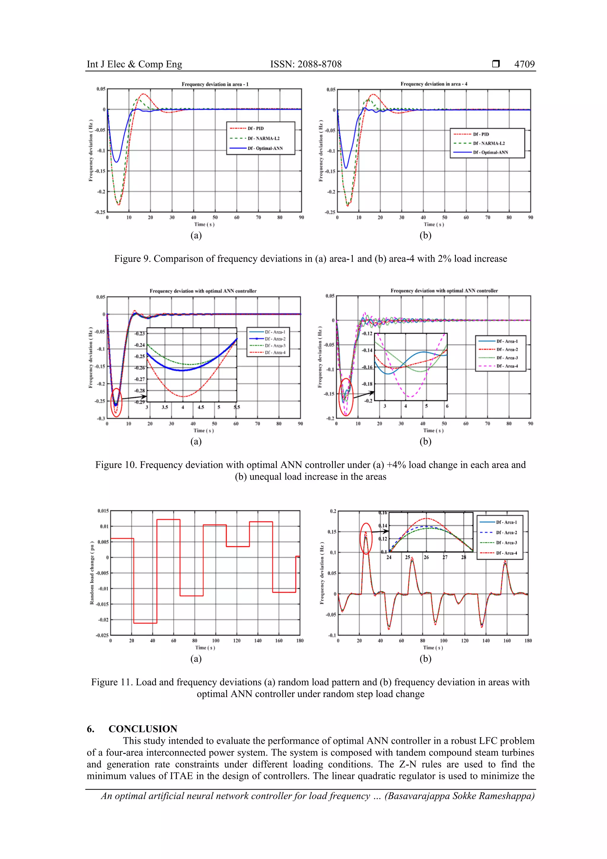
function. Figure 9 shows the comparison of frequency deviations in area-1 and area-4 with different
controllers under +2% step load change in each area. From Figures 9(a) and 9(b), the change in settling time
and maximum undershoot values are measured and tabulated in Table 3. As the load on the system increases
suddenly, its frequency decreases at that moment. The maximum undershoot decreases, oscillates, and settle
to zero steady state value quickly due to optimal ANN controller action compared to other two controllers.
This indicates that the system is stable even with +5% change in load.
It is evident from the Table 3 that the proposed optimal ANN controller gives stable responses with
a very minimum steady state error, lesser undershoot, lower settling time and the very smaller values of
MSE. Figure 10 shows the frequency deviation with optimal ANN controller under equal and unequal load
increase. Figure 10(a) shows for equal load (∆𝑃𝐿1 = ∆𝑃𝐿2 = ∆𝑃𝐿3 = ∆𝑃𝐿4 = 4%) in each area. Also, from
the Table 3, settling time is 21.8343 s and undershoot is -0.2572 Hz with a MSE value of 1 × 10⁻¹⁰
. These
values are smaller compared to that with PID and NARMA-L2 controllers [19], [20] for the same change in
load. Figure 10(b) shows the frequency deviation with optimal ANN controller under unequal load increase
(∆𝑃𝐿1 = 1%, ∆𝑃𝐿2 = 2%, ∆𝑃𝐿3 = 3%, ∆𝑃𝐿4 = 4%) in each area. Under this condition, proposed optimal
ANN controller gives good dynamic response with zero steady state error.
The load and frequency deviations in Figure 11 shows the robustness of the proposed optimal ANN
controller. Figure 11(a) shows a random load pattern and is more realistic in real power systems. All four
areas are encounter this type of load variations [15]. Under this condition, frequency deviation in all areas is
shown in Figure 11(b). It reveals that, optimal ANN controller successfully tracks the load pattern and balance
generation with load effectively with constant frequency. Only frequency deviation occurs for the equal change
in percentage of load in each area, whereas the algebraic sum of change in tie-line power flow is zero.
With optimal ANN controller in the four-area interconnected system, -0.0713 Hz and 23 s are the
maximum values of undershoot and settling time for +1% change in load, respectively. For +5% load change,
the peak undershoot is -0.3566 Hz and settling time is 22.9970 s. It is seen from the responses with 2%
increase in load causes a minimum undershoot of -0.1286 Hz and minimum settling time of 21.864 s. It is
observed that, the settling time is constant as the step load increases from 1% to 5%. The magnitude of
frequency deviation increases with load, but this increase is very small. On the other hand, as load decreases,
the frequency deviation increases with the same settling time. The ITAE values measured with PID and
NARMA-L2 controllers [20] are high compared to mean squared error values measured with optimal ANN
controller. The time response specification values obtained are smaller compared to their values in literatures
[28]–[32].
Table 3. Comparative study of settling time, maximum undershoot and error
∆PL Controllers Settling time (s) and error
in frequency deviation
Maximum undershoot (Hz) and error in frequency
deviation
Area-1 Area-2 Area-3 Area-4 ITAE/MSE Area-1 Area-2 Area-3 Area-4 ITAE/MSE
+ 1 %
PID 37.5065 37.1265 37.5065 36.8291 0.1128 -0.0741 -0.0752 -0.0741 -0.0749 0.1128
NARMA-L2 15.1145 15.0993 15.1078 26.6548 1e-3 -0.0670 -0.0681 -0.0670 -0.0705 1e-3
ANN 21.8390 23.0015 21.8396 21.9799 1e-10 -0.0643 -0.0656 -0.0643 -0.0713 1e-10
+ 2 %
PID 31.5815 31.5713 31.5815 31.4318 0.3229 -0.2334 -0.2341 -0.2334 -0.2358 0.3229
NARMA-L2 18.1999 18.4093 18.2013 18.9832 1e-3 -0.2297 -0.2297 -0.2297 -0.2336 1e-3
ANN 21.8640 23.0100 21.8640 21.9904 1e-10 -0.1286 -0.1312 -0.1286 -0.1427 1e-10
+ 3 %
PID 25.8792 25.8051 25.8792 25.8254 0.8842 -0.4649 -0.4649 -0.4649 -0.4714 0.8842
NARMA-L2 23.0941 23.1631 23.0240 22.8366 1e-3 -0.4582 -0.4582 -0.4582 -0.4657 1e-3
ANN 21.8428 22.9973 21.8439 21.9854 1e-10 -0.1929 -0.1968 -0.1929 -0.2140 1e-10
+ 4 %
PID 48.4521 49.0057 48.4521 47.7849 1.9070 -0.7439 -0.7438 -0.7439 -0.7502 1.9070
NARMA-L2 31.4917 31.7661 31.4906 32.1603 1e-3 -0.7284 -0.7284 -0.7284 -0.7319 1e-3
ANN 21.8347 22.9910 21.8343 21.9830 1e-10 -0.2572 -0.2624 -0.2572 -0.2853 1e-10
+ 5 %
PID 53.3577 53.7863 53.3577 52.8282 3.5370 -1.0526 -1.0526 -1.0526 -1.0549 3.5370
NARMA-L2 33.3008 33.5357 33.4160 33.9808 1e-3 -1.0146 -1.0146 -1.0146 -1.0222 1e-3
ANN 21.8419 22.9970 21.8414 21.9850 1e-10 -0.3215 -0.3280 -0.3215 -0.3566 1e-10](https://image.slidesharecdn.com/18157076107026749em11mar222sepn-220909025459-b3886cab/75/An-optimal-artificial-neural-network-controller-for-load-frequency-control-of-a-four-area-interconnected-power-system-9-2048.jpg)
![ ISSN: 2088-8708
Int J Elec & Comp Eng, Vol. 12, No. 5, October 2022: 4700-4711
4710
performance index and hence the mean squared error. The simulation results for the equal change in
percentage of load with proposed optimal ANN controller gives a significant improvement in terms of time
response specifications. The settling time, maximum undershoot, and objective function values compared to
tuned PID and NARMA-L2 controllers. The conventional controllers give higher values of error due to non-
linearity present in the system and loads. The robustness test of proposed optimal ANN controller is carried
out with random load pattern. The proposed controller performs satisfactorily under random step load
changes and thus desirable dynamic control of the system is achieved.
ACKNOWLEDGEMENTS
Authors are grateful to the Head of the Institute and Management of Bapuji Institute of Engineering
and Technology, Davanagere, Karnataka for their encouragement and support in completion this research
work.
REFERENCES
[1] P. Kundur, Control of active and reactive powers: Active power and frequency control, 1st ed. New York, USA: McGraw-Hill,
2006.
[2] D. P. Kothari and I. J. Nagrath, Automatic generation and voltage control, 4th ed. New Delhi, India: McGraw-Hill, 2013.
[3] H. Bevrani, Power system control, real power compensation, frequency control, frequency response characteristics and dynamic
performance, 2nd ed. New York, USA: Robust power system frequency control, 2009.
[4] S. Prasad and M. R. Ansari, “Frequency regulation using neural network observer based controller in power system,” Control
Engineering Practice, vol. 102, Sep. 2020, doi: 10.1016/j.conengprac.2020.104571.
[5] D. Qian and G. Fan, “Neural-network-based terminal sliding mode control for frequency stabilization of renewable power
systems,” IEEE/CAA Journal of Automatica Sinica, vol. 5, no. 3, pp. 706–717, May 2018, doi: 10.1109/JAS.2018.7511078.
[6] B. Bhatia, S. Saini, and N. Kumar, “Automatic generation control of multi area power systems using ANN controller,”
International Journal of Engineering Science and Technology, vol. 4, no. 7, pp. 3329–3334, 2012.
[7] N. Chettibi, A. M. Pavan, A. Mellit, A. J. Forsyth, and R. Todd, “Real-time prediction of grid voltage and frequency using
artificial neural networks: An experimental validation,” Sustainable Energy, Grids and Networks, vol. 27, Sep. 2021, doi:
10.1016/j.segan.2021.100502.
[8] K. Alzaareer, A. Q. Al-Shetwi, C. Z. El-bayeh, and M. B. Taha, “Automatic generation control of multi-area interconnected
power systems using ANN controller,” Revue d’Intelligence Artificielle, vol. 34, no. 1, pp. 1–10, Feb. 2020, doi:
10.18280/ria.340101.
[9] S. Prakash and S. K. Sinha, “Simulation based neuro-fuzzy hybrid intelligent PI control approach in four-area load frequency
control of interconnected power system,” Applied Soft Computing, vol. 23, pp. 152–164, Oct. 2014, doi:
10.1016/j.asoc.2014.05.020.
[10] K. Kumari, G. Shankar, S. Kumari, and S. Gupta, “Load frequency control using ANN-PID controller,” in 2016 IEEE 1st
International Conference on Power Electronics, Intelligent Control and Energy Systems (ICPEICES), Jul. 2016, pp. 1–6, doi:
10.1109/ICPEICES.2016.7853516.
[11] S. Prakash and S. K. Sinha, “Automatic load frequency control of six areas’ hybrid multi-generation power systems using neuro-
fuzzy intelligent controller,” IETE Journal of Research, vol. 64, no. 4, pp. 471–481, Jul. 2018, doi:
10.1080/03772063.2017.1361869.
[12] A. Mucka, A. Bardhi, and D. Qirollari, “Application of neural networks to load frequency control in power systems with four
control areas,” International Journal of Science and Research, vol. 8, no. 10, pp. 781–787, 2019, doi: 10.21275/ART20201887.
[13] P. S. R. Murthy, Load frequency control, Control of interconnected systems, 2nd ed. Hyderabad, India, B. S. Publications, 2008.
[14] F. M. Tuaimah, N. M. Al-Rawi, and W. A. Mahmoud, “Steam turbine governor design based on pole placement technique,”
International Journal of Computer Applications, vol. 92, no. 13, pp. 51–55, Apr. 2014, doi: 10.5120/16073-5306.
[15] E. Sahin, “Design of an optimized fractional high order differential feedback controller for load frequency control of a multi-area
multi-source power system with nonlinearity,” IEEE Access, vol. 8, pp. 12327–12342, 2020, doi:
10.1109/ACCESS.2020.2966261.
[16] K. Ogata, PID controls, Design of control systems in state space, 4th ed. New Jersey, USA: Prentice Hall, 2002.
[17] G. S. Thakur and A. Patra, “Load frequency control in single area with traditional Ziegler-Nichols PID tuning controller,”
International Journal of Research in Advent Technology, vol. 2, no. 12, pp. 49–53, 2014.
[18] R. Çelikel, “Speed control of BLDC using NARMA-L2 controller in single lnk manipulator,” Balkan Journal of Electrical and
Computer Engineering, vol. 7, no. 2, Apr. 2019, doi: 10.17694/bajece.510170.
[19] D. K. Sambariya and V. Nath, “Application of NARMA L2 controller for load frequency control of multi-area power system,” in
2016 10th International Conference on Intelligent Systems and Control (ISCO), 2016, pp. 1–7, doi: 10.1109/ISCO.2016.7726987.
[20] P. Sharma, “NARMA-L2 controller for five-area load frequency control,” Indonesian Journal of Electrical Engineering and
Informatics (IJEEI), vol. 2, no. 4, pp. 170–179, Dec. 2014, doi: 10.11591/ijeei.v2i4.123.
[21] A. Gundogdu and R. Celikel, “NARMA-L2 controller for stepper motor used in single link manipulator with low-speed-resonance
damping,” Engineering Science and Technology, an International Journal, vol. 24, no. 2, pp. 360–371, Apr. 2021, doi:
10.1016/j.jestch.2020.09.008.
[22] H. Patel, H. Raval, and K. Patil, “Automatic generation control for two area system using artificial neural network based
NARMA-L2 controller,” International Journal of Advance Engineering and Research Development, vol. 3, no. 05, pp. 463–470,
May 2016, doi: 10.21090/IJAERD.030571.
[23] N. N. Shah, “The state space modeling of single, two and three ALFC of power system using Integral control and optimal LQR
control method,” IOSR Journal of Engineering, vol. 02, no. 03, pp. 501–510, Mar. 2012, doi: 10.9790/3021-0203501510.
[24] Y. Zhang, X. Liu, and B. Qu, “Distributed model predictive load frequency control of multi-area power system with DFIGs,”
IEEE/CAA Journal of Automatica Sinica, vol. 4, no. 1, pp. 125–135, Jan. 2017, doi: 10.1109/JAS.2017.7510346.
[25] M. T. Hagan, H. B. Demuth, M. H. Beale, and O. De Jesus, Neuron models and network architectures, 2nd ed. USA: Martin](https://image.slidesharecdn.com/18157076107026749em11mar222sepn-220909025459-b3886cab/75/An-optimal-artificial-neural-network-controller-for-load-frequency-control-of-a-four-area-interconnected-power-system-11-2048.jpg)
![Int J Elec & Comp Eng ISSN: 2088-8708
An optimal artificial neural network controller for load frequency … (Basavarajappa Sokke Rameshappa)
4711
Hagan, ch. 2, 2014.
[26] P. M. Anderson and A. A. Fouad, “Typical system data” in power system control and stability, 2nd ed. New Jersey, USA: Wiley-
IEEE Press, 2003.
[27] M. Eremia and M. Shahidehpour, “Active power and frequency control,” in Handbook of electrical power system dynamics-
modelling, stability and control, New Jersey, USA: John Wiley & Sons, Inc, 2013, pp. 291–336.
[28] K. S. Kumar and A. Prasad, “Load frequency control of hydro‐thermal and nuclear interconnected power system using fuzzy and
ANN controllers,” International Journal of Science, Engineering and Technology, vol. 3, no. 3, pp. 582–589, 2015.
[29] J. Morsali, K. Zare, and M. T. Hagh, “Appropriate generation rate constraint (GRC) modeling method for reheat thermal units to
obtain optimal load frequency controller (LFC),” in 2014 5th Conference on Thermal Power Plants (CTPP), Jun. 2014,
pp. 29–34, doi: 10.1109/CTPP.2014.7040611.
[30] Y. Wei, I. Jayawardene, and G. K. Venayagamoorthy, “Optimal automatic generation controllers in a multi‐area interconnected
power system with utility‐scale PV plants,” IET Smart Grid, vol. 2, no. 4, pp. 581–593, 2019, doi: 10.1049/iet-stg.2018.0238.
[31] N. Patel and B. B. Jain, “Automatic generation control of four area power systems using ANN controllers,” International Journal
of Electrical, Electronics and Computer Engineering, vol. 3, no. 1, pp. 62–68, 2014.
[32] P. Rani and R. Jaswal, “Automatic load frequency control of multi-area power system using ANN controller and genetic
algorithm,” International Journal of Engineering Trends and Technology, vol. 4, no. 9, pp. 3777–3784, 2013.
BIOGRAPHIES OF AUTHORS
Basavarajappa Sokke Rameshappa received his B.E degree in Electrical
Engineering from RVCE, Bengaluru University in 1993 and M.E degree in Power Systems
from UVCE, Bengaluru University in 1996. He is working as Assistant Professor in Bapuji
Institute of Engineering and Technology, Davanagere, Karnataka, India. He has published two
papers in an IEEE conference and a journal. He is pursuing his Ph. D at Visvesvaraya
Technological University. His research interest includes power systems, load frequency
control, control systems and artificial intelligence (AI) techniques. He can be contacted at
email: basavarajsr@gmail.com.
Nagaraj Mudakapla Shadaksharappa received his B.E degree in Electrical and
Electronics in the year 1986 from Government BDT College of Engineering, Davanagere,
Karnataka, India. M. Tech degree in Power System from National Institute of Engineering,
Mysuru, Karnataka in 1991. Received the Ph. D degree in Electrical Engineering from
Visvesvaraya Technological University, Belagavi, Karnataka, India, in 2008. He has published
more than 40 papers in National, International Conferences and National Journals. He is
currently working as Professor and Head in the Department of Electrical and Electronics
Engineering, Bapuji Institute of Engineering and Technology, Davanagere, Karnataka, India.
His area of research interest includes electrical distribution systems, and AI applications to
power systems. He can be contacted at email: msndvg@gmail.com.](https://image.slidesharecdn.com/18157076107026749em11mar222sepn-220909025459-b3886cab/75/An-optimal-artificial-neural-network-controller-for-load-frequency-control-of-a-four-area-interconnected-power-system-12-2048.jpg)