Downloaded 21 times


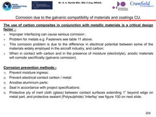

![Mr. G. A. Wardle MSc. MSc C.Eng. MRAeS.
Properties
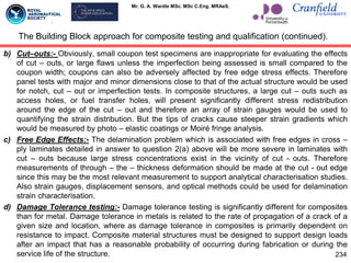
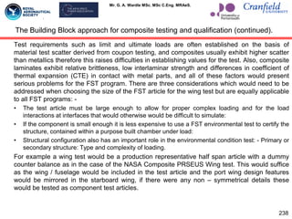
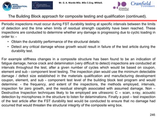
Effect of FVP on laminate mechanical properties.
0ºnt 90ºnt ±45ºns [(±45º)5/0º16/90º4]c
Ultimate strength
Varies directly
with FVP
Not sensitive to
FVP
Varies directly
with FVP
Varies directly
with FVP
Ultimate strain
Not sensitive to
FVP
Not sensitive to
FVP
Not sensitive to
FVP
Not sensitive to
FVP
Proportionality
limit stress
Varies directly
with FVP
Not sensitive to
FVP
Varies directly
with FVP
Varies directly
with FVP
Proportionality
limit strain
Varies directly
with FVP
Not sensitive to
FVP
Varies directly
with FVP
Varies directly
with FVP
Poisson‟s ratio
Not sensitive to
FVP
Not sensitive to
FVP
Varies directly
with FVP
Not sensitive to
FVP
Modulus of
elasticity
Varies directly
with FVP
Varies directly
with FVP
Varies directly
with FVP
Varies directly
with FVP
231
Table 12:- Effect of Fibre Volume Percentage (FVP) on laminate mechanical properties.](https://image.slidesharecdn.com/myairframecompositedesigncapabilitystudies-240624105336-ff711ea0/85/My-Airframe-Composite-Design-Capability-Studies-pdf-231-320.jpg)

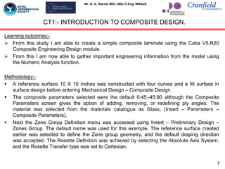
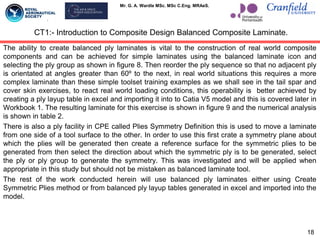
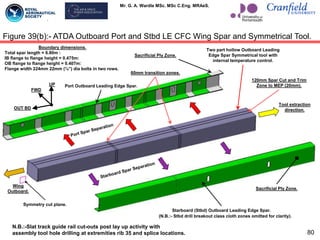
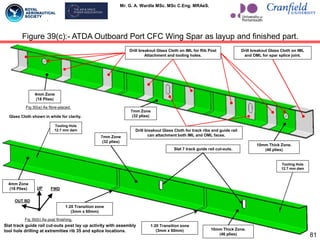
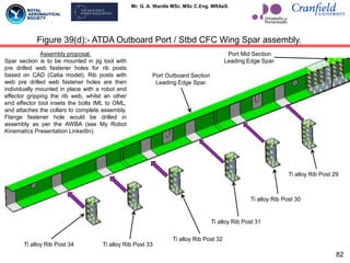
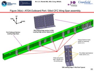
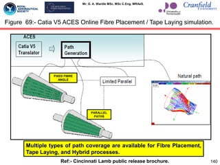
This document outlines Mr. G. A. Wardle's studies on airframe composite design, showcasing his work with the CATIA V5 R20 toolset to maintain and enhance his capabilities in aerospace engineering. The study is divided into sections covering baseline capabilities, design standards, and practical applications of composite engineering modules, alongside detailed methodologies for creating composite laminates. The ongoing research is aimed at supporting the Advanced Technology Demonstrator Aircraft project and reflects the development progress in composite materials and design techniques.


![[ Capella Day 2019 ] Model-based safety analysis on Capella using Component F...](https://cdn.slidesharecdn.com/ss_thumbnails/capella-dayslideshandout-191002122651-thumbnail.jpg?width=640&height=640&fit=bounds)


