Download to read offline

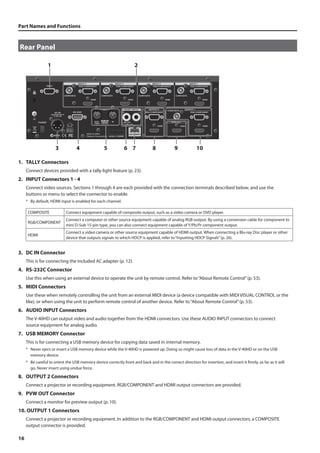
![5
Power Supply
301 (QA-EMC)
• Do not connect this unit to same electrical outlet that is being used
by an electrical appliance that is controlled by an inverter or a motor
(such as a refrigerator, washing machine, microwave oven, or air
conditioner). Depending on the way in which the electrical appliance
is used, power supply noise may cause this unit to malfunction or may
produce audible noise. If it is not practical to use a separate electrical
outlet, connect a power supply noise filter between this unit and the
electrical outlet.
302
• The AC adaptor will begin to generate heat after long hours of
consecutive use. This is normal, and is not a cause for concern.
307
• To prevent malfunction and equipment failure, always make sure
to turn off the power on all your equipment before you make any
connections.
309
• With the factory settings, the V-40HD will automatically be switched
off when the conditions described below continue for 240 minutes.
If you don’t want the unit to turn off automatically, refer to “Menu
Operations” (p. 45) and turn the [AUTO OFF] setting to [OFF] in
System menu (p. 50).
• No operation of the unit (including operation by remote control)
• No video input
• No audio input at -48 dBu or higher
* The settings you were editing will be lost when the unit is turned
off. If you want to keep your settings, you must save your settings
before turning the unit off.
Placement
351 (QA-EMC)
• Using the unit near power amplifiers (or other equipment containing
large power transformers) may induce hum. To alleviate the problem,
change the orientation of this unit; or move it farther away from the
source of interference.
352a (QA-EMC)
• This device may interfere with radio and television reception. Do not
use this device in the vicinity of such receivers.
352b (QA-EMC)
• Noise may be produced if wireless communications devices, such as cell
phones, are operated in the vicinity of this unit. Such noise could occur
when receiving or initiating a call, or while conversing. Should you
experience such problems, you should relocate such wireless devices so
they are at a greater distance from this unit, or switch them off.
354a
• Do not expose the unit to direct sunlight, place it near devices that
radiate heat, leave it inside an enclosed vehicle, or otherwise subject it
to temperature extremes. Excessive heat can deform or discolor the unit.
355b
• When moved from one location to another where the temperature
and/or humidity is very different, water droplets (condensation) may
form inside the unit. Damage or malfunction may result if you attempt
to use the unit in this condition. Therefore, before using the unit, you
must allow it to stand for several hours, until the condensation has
completely evaporated.
360
• Depending on the material and temperature of the surface on which
you place the unit, its rubber feet may discolor or mar the surface.
• You can place a piece of felt or cloth under the rubber feet to prevent
this from happening. If you do so, please make sure that the unit will
not slip or move accidentally.
361
• Do not put anything that contains water on this unit. Also, avoid the
use of insecticides, perfumes, alcohol, nail polish, spray cans, etc., near
the unit. Swiftly wipe away any liquid that spills on the unit using a
dry, soft cloth.
Maintenance
401a
• For everyday cleaning wipe the unit with a soft, dry cloth or one that
has been slightly dampened with water. To remove stubborn dirt, use
a cloth impregnated with a mild, non-abrasive detergent. Afterwards,
be sure to wipe the unit thoroughly with a soft, dry cloth.
402
• Never use benzine, thinners, alcohol or solvents of any kind, to avoid
the possibility of discoloration and/or deformation.
Repairs and Data
452
• Please be aware that all data contained in the unit’s memory may be
lost when the unit is sent for repairs. Important data should always
be backed up to USB memories, or written down on paper (when
possible). During repairs, due care is taken to avoid the loss of data.
However, in certain cases (such as when circuitry related to memory
itself is out of order), we regret that it may not be possible to restore
the data, and Roland assumes no liability concerning such loss of data.
Additional Precautions
551
• Please be aware that the contents of memory can be irretrievably lost
as a result of a malfunction, or the improper operation of the unit.
To protect yourself against the risk of loosing important data, we
recommend that you periodically save a backup copy of important
data you have stored in the unit’s memory to USB memories.
552
• Unfortunately, it may be impossible to restore the contents of data
that was stored in the unit’s internal memory or USB memories once
it has been lost. Roland Corporation assumes no liability concerning
such loss of data.
553
• Use a reasonable amount of care when using the unit’s buttons,
sliders, or other controls; and when using its jacks and connectors.
Rough handling can lead to malfunctions.
556
• When disconnecting all cables, grasp the connector itself, never pull
on the cable. This way you will avoid causing shorts, or damage to the
cable’s internal elements.
558b
• To avoid disturbing others nearby, try to keep the unit’s volume at
reasonable levels.
559a
• When you need to transport the unit, package it in the box (including
padding) that it came in, if possible. Otherwise, you will need to use
equivalent packaging materials.
562
• Some audio connection cables contain resistors. Do not use cables
that incorporate resistors for connecting to this unit. The use of such
cables can cause the sound level to be extremely low, or impossible
to hear. For information on cable specifications, contact the
manufacturer of the cable.
Before Using USB Memories
704
• Carefully insert the USB memories all the way in - until it is firmly in
place.
705
• Never touch the terminals of the USB memories. Also, avoid getting
the terminals dirty.
708
• USB memories are constructed using precision components; handle
the memories carefully, paying particular note to the following.
• To prevent damage to the cards from static electricity, be sure to
discharge any static electricity from your own body before handling
the cards.
• Do not touch or allow metal to come into contact with the contact
portion of the cards.
• Do not bend, drop, or subject cards to strong shock or vibration.
• Do not keep cards in direct sunlight, in closed vehicles, or other
such locations.
• Do not allow cards to become wet.
• Do not disassemble or modify the cards.
IMPORTANT NOTES](https://image.slidesharecdn.com/v-40hde05w-140903070030-phpapp02/85/Multi-format-Video-Switcher-5-320.jpg)
![About the Preview Monitor
Connecting the Monitor
10
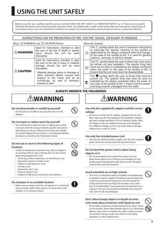
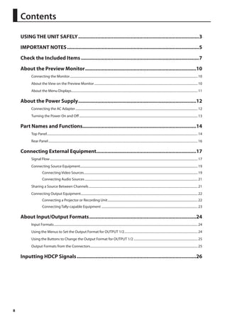
To operate the V-40HD, a preview monitor must be connected. Connect a monitor that supports HDMI input to the PVW OUT
connector.
fig.connect-monitor.eps
HDMI
The resolution and refresh rate of monitor output are fixed at 1920 x 1080/60 Hz (progressive). Connect a monitor that supports this resolution and
refresh rate. Also, the monitor must support HDCP (High-bandwidth Digital Content Protection) signals. PVW Output shows blue screen when a non
HDCP compliant monitor is connected, but Menu is in function.
About the View on the Preview Monitor
Use the PVW (Preview) selector on the top panel to choose the view displayed on the preview monitor.
fig.preview-select.eps
You can select one from the following four views to display.
INPUT This displays the input source picture using a four-way split screen. (The display frame rate of the preview drops when this setting is used.)
PST The picture of standby channel is displayed.
PGM The picture on the current output channel is displayed.
DSK This previews the status of DSK composition. Adjust the amount of keying in this mode.
fig.INPUT-view.eps
CH.1 HDMI CH.2 HDMI
Presented by
CH.3 HDMI CH.4 HDMI
* When [INPUT] has been selected, a red border is displayed around the channel of current program output. A green border is displayed around
the channel that is on standby.
* The input source pictures are displayed in the preview monitor directly (without any parameter changes). Settings such as color adjustment or
scaling are not applied.
When [INPUT] has been selected, the frame rate drops by about 5 fps. The frame rate does not fall when a setting other than [INPUT] is selected.
When the source signal is interlace, the displayed image moves up and down for 1 line width.
You can change the text labels for [CH 1] through [CH 4]. Refer to “Changing the Preview Labels” (p. 43).](https://image.slidesharecdn.com/v-40hde05w-140903070030-phpapp02/85/Multi-format-Video-Switcher-10-320.jpg)
![About the Preview Monitor
11
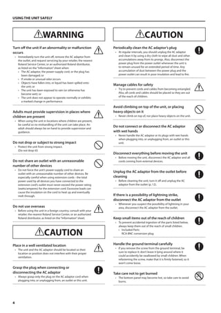
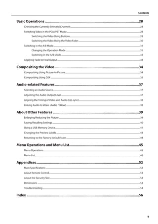
About SD Source Preview
When the source is SD, the display does not use the entire screen. The display is as follows.
fig.SD-preview.eps
CH.1 CMP
About the Menu Displays
Pressing the [MENU] button on the top panel displays the menu in the preview monitor. To make the displayed menu disappear,
press the [EXIT] button on the top panel.
fig.menu-display.eps
Presented by
Setup
Input
Output
Transition
PinP
DSK
Audio
System
Enter
Enter
Enter
Enter
Enter
Enter
Enter
For information on using the menus and on menu items, refer to “Menu Operations and Menu List” (p. 45).](https://image.slidesharecdn.com/v-40hde05w-140903070030-phpapp02/85/Multi-format-Video-Switcher-11-320.jpg)
![About the Power Supply
13
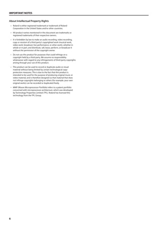
Turning the Power On and Off
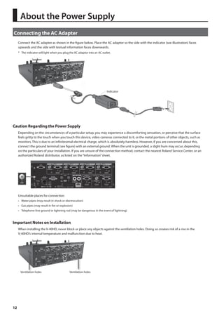
Once everything is properly connected, be sure to follow the procedure below to turn on their power. If you turn on equipment in
the wrong order, you risk causing malfunction or equipment failure.
* This unit is equipped with a protection circuit. A brief interval (a few seconds) after turning the unit on is required before it will operate normally.
Turning the Power On
1. Connect the peripheral devices.
Connect any video cameras and other equipment. Make the connections while the power to all equipment, including the V-40HD,
is turned off.
2. Turn on the power to the V-40HD.
Make sure the power cable is securely inserted, then press the [POWER] button located on the rear panel. The buttons and
indicators on the top panel flash, and the V-40HD starts up.
When the V-40HD starts up, the settings saved at memory number 1 in bank 1 are loaded (p. 40).
fig.power-button.eps
3. Turn on the power to the source devices.
Turn on the power to the source devices such as video cameras connected to the V-40HD.
4. Turn on the power to the output devices.
Turn on the power to the output devices such as projectors connected to the V-40HD.
Turning the Power Off
1. Turn off the power to the output devices.
Turn off the power to the output devices such as projectors connected to the V-40HD.
2. Turn off the power to the V-40HD.
Set the [POWER] switch on the rear panel to OFF to turn off the power to the V-40HD.
3. Turn off the power to the source devices.
Turn off the power to the source devices such as video cameras connected to the V-40HD.
Never turn off the power while a message such as “Processing...” is shown in the menu display area of the preview monitor. Doing so might cause
settings not to be saved properly.
About AUTO OFF
When all of the conditions described below continue for 240 minutes, the AUTO OFF feature automatically turns off the power to
the V-40HD.
• No operation of the unit (including operation by remote control)
• No video input
• No audio input at -48 dBu or higher
The settings you were editing will be lost when the unit is turned off. If you want to keep your settings, you must save your settings before turning
the unit off.
You can disable the AUTO OFF feature by going to the System menu and setting [AUTO OFF] to [OFF]. Refer to “Menu Operations” (p. 45) and
“System Menu” (p. 49).](https://image.slidesharecdn.com/v-40hde05w-140903070030-phpapp02/85/Multi-format-Video-Switcher-13-320.jpg)
![Part Names and Functions
Top Panel
fig.top-panel.eps
14
1 2 3 5 6
7
8
9
10 11 12 13
14
15
4
1. MEMORY Buttons
Use these to save the current settings to the internal memory (p. 40).
2. PVW (Preview) Selectors
These select the picture to output from the [PVW OUT] connector on the rear panel.
3. OUTPUT Selectors
Use the [FORMAT] button to switch the output format for OUTPUT 1 and 2.
* The format of PVW OUT cannot be changed.
4. AUDIO Indicators
These display the audio output level.
5. HDCP Indicator
This operates as described below, depending on the setting for HDCP signals (p. 26).
Lighted It lights up when an HDCP-compatible device is connected as the output device.
Flashing It flashes when no output device is connected or when the connected device is not compatible with HDCP.
Unlighted It goes dark when the V-40HD’s HDCP-signal input/output mode is off.
6. OUTPUT FADE Button
This applies fade to final output. The button flashes while the fade is in progress. The button lights up continuously when a fade-out
has been completed. The button goes dark when a fade-in has been completed (p. 33).
* By default, the fade time is set at 0.5 seconds, and the fade goes to black. Use the menus (p. 50) to change the fade time and fade color.](https://image.slidesharecdn.com/v-40hde05w-140903070030-phpapp02/85/Multi-format-Video-Switcher-14-320.jpg)
![Part Names and Functions
15
7. SCALING Section
Use the controls in this section to zoom the screen in/out or adjust the display position. When you are applying Picture-in-Picture,
use the controls in this section to adjust the size and display position of the inset screen.
8. TRANSITION Dial and Indicator
Use this dial to set the transition time.
* By default, the unit displays the transition time in seconds.. Use the menus (p. 48) to select a different unit (frames or seconds + frames).
9. Input Selectors
This has 5 buttons each in the A-BUS/PGM and B-BUS/PST sections. Use these to select the output video and standby video.
A-BUS/PGM
When you are making a selection while in the PGM/PST mode (p. 28), the button for the current output channel lights up red.
When you are making a selection while in the A/B mode (p. 31), these choose the channel for A-Bus.
B-BUS/PST
When you are making a selection while in the PGM/PST mode, these choose the channel you want to output next (standby).
When you are making a selection while in the A/B mode, these choose the channel for B-Bus.
Use the HDMI, RGB/COMPONENT, and COMPOSITE buttons to assign sources to each channel (p. 19). The lighted color and dark
state of these buttons are switched as described below.
Red This is the default. In this mode, assign a source after pressing a button (1 to 4) in the bus of current output.
Green In this mode, assign a source after pressing a button (1 to 4) in the bus of standby.
Orange The button lights up orange when sharing a source (p. 21).
Unlighted In this mode, sources cannot be assigned using the HDMI, RGB/COMPONENT, and COMPOSITE buttons.
The [INPUT STATUS] indicators light up when the assignment and the input match. They do not light up when the assignment and
input are different.
10. PinP Selectors
Pressing one of the buttons from 1 to 4 applies picture-in-picture.
11. WIPE PATTERN Selectors
These select a transition effect.
* Use the menus to assign other wipe patterns to the WIPE 1 and 2 buttons.
12. AUTO Button
Pressing this button outputs the standby channel. Pressing this button applies the effect selected using the [WIPE PATTERN]
buttons, for the time set using the [TRANSITION] dial.
13. Video Fader
Use this to apply a transition manually. When the transition is made manually, the time for the transition effect changes depending
on the movement of the video fader, regardless of the setting made using the [TRANSITION] dial.
14. SETUP Section
Use this when displaying the menu screen to change settings on the V-40HD (p. 45).
15. DSK Section
When performing DSK composition, pressing the [AUTO] button in this section to make the DSK source (foreground video) appear
or disappear. Also adjust the amount of keying by turning the [KEY LEVEL] dial (p. 35).
* By default, the setting is to apply black extraction. Use the menus (p. 49) to change the settings.](https://image.slidesharecdn.com/v-40hde05w-140903070030-phpapp02/85/Multi-format-Video-Switcher-15-320.jpg)
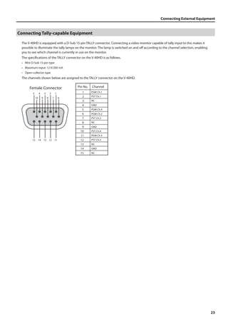
![Connecting External Equipment
19
Connecting Source Equipment
Connecting Video Sources
Use the menus to assign sources to channels instead of using the button operations described below. Select a channel (Ch. 1 - Ch. 4) in the Input
menu (p. 46), then select the source to assign.
Making an HDMI Connection
Connect video cameras or other devices capable of HDMI output to the HDMI connectors at INPUT 1 through 4.
fig.HDMI-connection.eps
To assign HDMI input to channel 1, go to [A-BUS/PGM] and press [1], then press the [HDMI] button. When the V-40HD detects the
HDMI input, the [INPUT STATUS] indicator of the channel 1 lights up.
fig.select-HDMI-in.eps
To connect a computer capable of DVI output, use a DVI - HDMI conversion cable to make the connection to an HDMI connector.
Making an RGB Connection
Connect computers or other devices capable of RGB output to the RGB/COMPONENT connectors at INPUT 1 through 4.
fig.connect-PC-RGB.eps
To assign RGB input to channel 4, go to [A-BUS/PGM] and press [4], then press the [RGB/COMPONENT] button. When the V-40HD
detects the RGB input, the [INPUT STATUS] indicator of the channel 4 lights up.
fig.select-rgb-in.eps](https://image.slidesharecdn.com/v-40hde05w-140903070030-phpapp02/85/Multi-format-Video-Switcher-19-320.jpg)
![Connecting External Equipment
Making a Component Connection
20
Connect video cameras or other devices capable of component output to the RGB/COMPONENT connectors at INPUT 1 through 4.
When doing this, use a conversion cable for component to mini D-Sub 15-pin type.
fig.component-connection.eps
female connector
-----------
9 ----------- 6
5 1
15 ---------- 10
1 : Pr
2 : Y
3 : Pb
6 : GND (Pr)
7 : GND (Y)
8 : GND (Pb)
To assign component input to channel 2, go to [A-BUS/PGM] and press [2], then press the [RGB/COMPONENT] button. When the
V-40HD detects the component input, the [INPUT STATUS] indicator of the channel 2 lights up.
fig.select-component-in.eps
Making a Composite Connection
Connect video cameras, DVD players, or other devices capable of composite output to the COMPOSITE connectors at INPUT 1
through 4.
* When connecting equipment that has an RCA type output jack, use the included RCA - BNC conversion plug.
fig.composite-connection.eps
To assign composite input to channel 3, go to [A-BUS/PGM] and press [3], then press the [COMPOSITE] button. When the V-40HD
detects the composite input, the [INPUT STATUS] indicator of the channel 3 lights up.
fig.select-composite-in.eps
By default, [1] through [4] in the current output bus are used to assign input sources. Changing the mode lets you perform these operations using
the buttons in the standby bus. You can also disable (set to OFF) operation of the [HDMI], [RGB/COMPONENT], and [COMPOSITE] buttons. Go to the
System menu (p. 49) and use [Source Assign Mode] to make the changes.](https://image.slidesharecdn.com/v-40hde05w-140903070030-phpapp02/85/Multi-format-Video-Switcher-20-320.jpg)
![Connecting External Equipment
21
Connecting Audio Sources
Connect audio mixers or other audio sources to the AUDIO INPUT connectors. Input made via these connectors is output from
HDMI connectors in the OUTPUT 1/2 sections together with the results of video mixing on the V-40HD.
* When connection cables with resistors are used, the volume level of equipment connected to the inputs (AUDIO INPUT) may be low. If this
happens, use connection cables that do not contain resistors.
fig.audio-connection.eps
Audio Mixer
This unit is equipped with balanced (TRS) type jacks. Wiring diagrams for these jacks are shown below. Make connections after first checking the
wiring diagrams of other equipment you intend to connect.
fig.TRS_jack.eps
Use the menus to adjust the audio level (p. 37) or delay its timing to sync it with the video (p. 38).
Sharing a Source Between Channels
Channels 1 through 4 can share a source. Using this feature, you can assign the video on channel 1 to channels 2 through 4. When
shared, a single source video is assigned to multiple channels. To share a source, go to the Input menu (p. 45) and select [Shared
Input] in the input format display area.
* Only the source of the previous adjacent channel can be shared. Therefore, when sharing the source on channel 1 with channels 2 through 4,
[Shared Input] must be selected for each channel from 2 to 4.
fig.shared-input.eps
HDMI
RGB/
Component
Composite
HDMI
Shared
Input
RGB/
Component
Composite
HDMI
Shared
Input
RGB/
Component
Composite
HDMI
Shared
Input
RGB/
Component
Composite
Ch 1 Ch 2 Ch 3 Ch 4
Audio sources cannot be shared.](https://image.slidesharecdn.com/v-40hde05w-140903070030-phpapp02/85/Multi-format-Video-Switcher-21-320.jpg)
![About Input/Output Formats
Input Formats
24
It is possible to input signal of various formats to INPUT 1-4 of the V-40HD.
Signals of the following formats can be input. The input format is detected automatically.
Frame Rate 59.94 Hz 50 Hz
COMPOSITE NTSC) PAL
COMPONENT 480/59,94i, 480/59.94p, 720/59.94p, 1080/59.94i, 1080/59.94p 576/50i, 576/50p, 720/50p, 1080/50i, 1080/50p
RGB
640 x 480/60 Hz, 800 x 600/60 Hz, 1024 x 768/60 Hz, 1280 x 768/60 Hz, 1280 x 1024/60 Hz, 1366 x 768/60 Hz,
1400 x 1050/60 Hz, 1600 x 1200/60 Hz, 1920 x 1080/60 Hz, 1920 x 1200/60 Hz (Reduced Blanking)
HDMI
480/59,94i, 480/59.94p, 720/59.94p, 1080/59.94i, 1080/59.94p 576/50i, 576/50p, 720/50p, 1080/50i, 1080/50p
640 x 480/60 Hz, 800 x 600/60 Hz, 1024 x 768/60 Hz, 1280 x 768/60 Hz, 1280 x 1024/60 Hz, 1366 x 768/60 Hz,
1400 x 1050/60 Hz, 1600 x 1200/60 Hz, 1920 x 1080/60 Hz, 1920 x 1200/60 Hz (Reduced Blanking)
* HDMI audio input format is Linear PCM, 24 bits/48 kHz, 2ch.
Using the Menus to Set the Output Format for OUTPUT 1/2
You can use the menus to the set the output format for OUTPUT 1 and 2.
* The output signal format of the COMPOSITE connector in OUTPUT 1 is NTSC or PAL. A common format is output from the HDMI and RGB/
COMPONENT connectors in OUTPUT 1/2.
1. Display the Output menu.
Press the [MENU] button to display the menu. Use the [CURSOR] buttons to select [Output], then press the [ENTER] button to
display the Output menu.
fig.open-output-menu.eps
2. Set the output format.
Turn the [VALUE] dial to set the output format.
fig.select-out-format.eps
You can independently set various parameters for OUTPUT 1 and 2. Refer to Output menu (p. 46).
If one of below is selected as the output format, signal output from the RGB/COMPONENT connector is disabled.
• 480/59.94i (NTSC)
• 576/50i (PAL)
• 1080/59.94i
• 1080/50i](https://image.slidesharecdn.com/v-40hde05w-140903070030-phpapp02/85/Multi-format-Video-Switcher-24-320.jpg)
![About Input/Output Formats
25
Using the Buttons to Change the Output Format for OUTPUT 1/2
Use the OUTPUT selectors on the top panel to change the output format. Press the [FORMAT] button to change the illuminated
indicator.
fig.switch-output.eps
By default, the following signals are output. The signal format that is output changes according to the setting described in the
previous section.
Frame Rate 59.94 Hz 50 Hz
SD NTSC PAL
HD 1080/59.94i 1080/50i
RGB 1024 x 768/60 Hz 1024 x 768/75 Hz
Output Formats from the Connectors
Signals in the following formats can be output from the respective output connectors on the V-40HD. Refer to Output Menu (p. 46).
OUTPUT 1/2
Frame Rate 59.94 Hz 50 Hz
COMPOSITE (*1)(*2) NTSC PAL
COMPONENT (*2) 480/59.94p, 720/59.94p, 1080/59.94p 576/50p, 720/50p, 1080/50p
RGB (*2)
640 x 480/60 Hz, 800 x 600/60 Hz, 1024 x 768/60 Hz,
1280 x 768/60 Hz, 1280 x 1024/60 Hz, 1366 x 768/60 Hz,
1400 x 1050/60 Hz, 1600 x 1200/60 Hz,
1920 x 1200/60 Hz (Reduced Blanking)
640 x 480/75 Hz, 800 x 600/75 Hz, 1024 x 768/75 Hz,
1280 x 768/75 Hz, 1280 x 1024/75 Hz, 1366 x 768/75 Hz,
1400 x 1050/75 Hz, 1600 x 1200/60 Hz,
1920 x 1200/60 Hz (Reduced Blanking)
HDMI
480/59,94i, 480/59.94p, 720/59.94p, 1080/59.94i, 1080/59.94p 576/50i, 576/50p, 720/50p, 1080/50i, 1080/50p
640 x 480/60 Hz, 800 x 600/60 Hz, 1024 x 768/60 Hz,
1280 x 768/60 Hz, 1280 x 1024/60 Hz, 1366 x 768/60 Hz,
1400 x 1050/60 Hz, 1600 x 1200/60 Hz,
1920 x 1200/60 Hz (Reduced Blanking)
640 x 480/75 Hz, 800 x 600/75 Hz, 1024 x 768/75 Hz,
1280 x 768/75 Hz, 1280 x 1024/75 Hz, 1366 x 768/75 Hz,
1400 x 1050/75 Hz, 1600 x 1200/60 Hz,
1920 x 1200/60 Hz (Reduced Blanking)
*1 : OUTPUT 1 only
*2 : No output while the HDCP setting is ON (p. 26).
PVW OUT
Frame Rate 59.94 Hz 50 Hz
HDMI 1920 x 1080/60 Hz
* HDMI audio output format of OUTPUT 1/2 and PVW OUT is Linear PCM, 24 bits/48 kHz, 2ch.](https://image.slidesharecdn.com/v-40hde05w-140903070030-phpapp02/85/Multi-format-Video-Switcher-25-320.jpg)
![26
By default, the HDCP (High-bandwidth Digital Content Protection) setting of the V-40HD is turned off. This means that HDCP-applied
signals from Blu-ray Disc players and the like cannot be input. When inputting signals to which HDCP is applied, follow the
procedure shown below to change the setting.
* HDCP is copyright-protection technology that prevents unlawful copying of content by encoding the path when sending digital signals from a
video playback device to a display monitor or other display equipment.
1. Display the System menu.
Press the [MENU] button to display the menu. Use the [CURSOR] buttons to select [System], then press the [ENTER] button to
display the System menu.
fig.open-system-menu.eps
2. Change the setting.
Use the [CURSOR] buttons to select [HDCP]. Turn the [VALUE] dial to change the setting from [OFF] to [ON]. When the confirmation
screen appears, press the [ENTER] button.
fig.HDCP-setting.eps
3. Exit the menu.
Press the [EXIT] button several times to quit the menu.
When the setting change just described has been made, no further output is made from the COMPOSITE and RGB/COMPONENT connectors in
OUTPUT 1 and 2. Note, however, that HDCP-applied signals are output from the HDMI connectors.
fig.HDCP-on-off.eps
HDCP OFF HDCP ON
HDMI
(with HDCP)
HDMI
(without HDCP)
RGB/
COMPONENT
COMPOSITE
OUTPUT1
PVW OUT
INPUT1-4
OUTPUT2
HDMI
(without HDCP)
RGB/
COMPONENT*
COMPOSITE
HDMI
(without HDCP)
RGB/
COMPONENT *
HDMI
(with HDCP)
* No signal is output when the OUTPUT FORMAT is set to
480/59.94i, 576/50i, 1080/59.94i or 1080/50i.
HDMI
(with HDCP)
RGB/
COMPONENT
COMPOSITE
OUTPUT1
PVW OUT
INPUT1-4
OUTPUT2
HDMI
(without HDCP)
HDMI
(with HDCP)
HDMI
(with HDCP)
HDMI
(with HDCP)
Inputting HDCP Signals](https://image.slidesharecdn.com/v-40hde05w-140903070030-phpapp02/85/Multi-format-Video-Switcher-26-320.jpg)
![Inputting HDCP Signals
27
About the HDCP Indicator
The [HDCP] indicator on the top panel operates as described below.
Lighted Turn on the HDCP setting and HDCP-compatible device(s) is connected to any of the HDMI connectors of OUTPUT 1/2 or PVW OUT.
Flashing
Turn on the HDCP setting but no device is connected to any of the HDMI connectors of OUTPUT 1/2 or PVW OUT. Same thing happens
when a device not compatible with HDCP is connected.
Unlighted The HDCP setting is turned off.
* The above operation is not related to inputs, detected from devices connected to output connectors only.
About Verification of HDCP-compatible Equipment
You can examine the HDCP compatibility of source equipment and output equipment. Open Input menu or Output menu. You can
see [HDCP] indications like below if the connected devices are compatible.
fig.HDCP-confirm.eps](https://image.slidesharecdn.com/v-40hde05w-140903070030-phpapp02/85/Multi-format-Video-Switcher-27-320.jpg)
![28
Basic Operations
Using this unit makes it possible to create video transitions that occur at extremely high speeds. Depending on physical condition, viewing such
video might cause headache or discomfort. Never use this unit to create or present such video that might be distressful to health. Roland assumes
no responsibility in the event of any distress experienced by you or other viewers.
Checking the Currently Selected Channels
Before you carry out a transition, check which channels are currently selected. Immediately after turning the V-40HD on, MEMORY
1-1 (No. 1 in bank 1) is selected. The channels in the panel state saved at 1-1 are selected.
* For information on saving data to MEMORY buttons, refer to “Saving/Recalling Settings” (p. 40).
In the [INPUT] mode of the preview monitor, a red border is displayed around the video currently being output, and a green border
is displayed around the video on standby.
At the [A-BUS/PGM] input selectors, the button for the channel currently being output lights up red. At [B-BUS/PST], the button for
the channel currently on standby lights up green.
fig.current-selection.eps
CH.1 HDMI CH.2 HDMI
Presented by
CH.3 HDMI CH.4 HDMI
Red
Green
Red Green
Switching Video in the PGM/PST Mode
The default operation mode of the V-40HD is the PGM/PST mode. You can also select the A/B mode (p. 31).
Switching the Video Using Buttons
Use the [AUTO] button to switch the video. The effect selected using the [WIPE PATTERN] buttons is applied for the time set using
the [TRANSITION] dial.
1. Move the video fader all the way.
Move the video fader all the way toward either the front or the back.
fig.fader-max.eps
or](https://image.slidesharecdn.com/v-40hde05w-140903070030-phpapp02/85/Multi-format-Video-Switcher-28-320.jpg)
![Basic Operations
1 A Video sources wipe from one to the other
B Video sources wipe from one to the other
29
2. Select a transition effect.
Use the [WIPE PATTERN] buttons to select the transition effect you want to apply.
* Using the [CUT] button makes the video change instantly, with no transition effect applied.
fig.transition-select.eps
Start Finish
B
B
CUT A No transition eect is applied.
MIX A AB Video sources blend together during the
switch process.
2 A A
during the switch process.
(default : horizontal wipe).
B
B
during the switch process.
(default : vertical wipe).
AB
3. Set the transition time.
Operate the [TRANSITION] dial to set the time for which the transition effect is applied.
fig.transition-time.eps
4. Select the video you want to output next.
Use the input selectors in the [B-BUS/PST] section to select the channel of the video you want to output next (standby). The
indicator for the pressed button lights up green. In the [INPUT] mode of the preview monitor, a green border is displayed around
the selected channel.
fig.standby-channel.eps
Green
5. Output the selected video.
Press the [AUTO] button. The final output changes to the video on the channel selected in step 4.
* When a [WIPE PATTERN] button other than [CUT] has been selected, the [AUTO] button indicator flashes while the transition effect is applied.
fig.press-AUTO.eps
When the transition is complete, the input selector in the [A-BUS/PGM] section for the channel selected in step 4 lights up red.
Also, in the [INPUT] mode for the preview monitor, a red border is displayed around the video on that channel.
The channel that was output before the [AUTO] button was pressed changes to the standby channel at this time.
While the transition is in progress (that is, while the transition effect is being applied), the [AUTO] button indicator flashes.](https://image.slidesharecdn.com/v-40hde05w-140903070030-phpapp02/85/Multi-format-Video-Switcher-29-320.jpg)
![Basic Operations
Switching the Video Directly
30
It is also possible to directly switch the video pressing the buttons in [A-BUS/PGM] section. However, a short black image is inserted
between 2 video images on the conditions below.
• When a direct switching operation is carried out while a logo/text is composited using the DSK function (p. 35).
• [DSK] is selected as the dislay mode of preview monitor and [PST] is selected as the output source for OUTPUT 1/2.
• [DSK] is selected as the output source for OUTPUT 1/2.
Switching the Video Using the Video Fader
When you use the [AUTO] button, the transition effect is applied for the time set using the [TRANSITION] dial. When you use the
video fader to perform a transition, you can control the length of the transition time manually.
1. Move the video fader all the way.
Before you carry out a transition operation, move the video fader all the way toward either the front or the back.
fig.fader-max.eps
or
2. Select a transition effect.
Use the [WIPE PATTERN] buttons to select the transition effect you want to apply.
* If you select [CUT], the transition occurs when the video fader is at its center position.
3. Select the channel you want to output next.
Use the input selectors in the [B-BUS/PST] section to select the channel of the video you want to output next (standby).
4. Switch the output video.
Move the video fader in the opposite direction of step 1. Moving it all the way makes the final output switch to the video on the
channel selected in step 3.
fig.move-fader.eps](https://image.slidesharecdn.com/v-40hde05w-140903070030-phpapp02/85/Multi-format-Video-Switcher-30-320.jpg)
![Basic Operations
31
Switching in the A/B Mode
Changing the Operation Mode
For information on using the menus, also refer to “Menu Operations and Menu List” (p. 45).
1. Display the System menu.
Press the [MENU] button to display the menu. Use the [CURSOR] buttons to select [System], then press the [ENTER] button to
display the System menu.
fig.open-system-menu.eps
2. Select [Panel Mode].
Use the [CURSOR] buttons to select [Panel Mode].
fig.panel-mode-setup.eps
3. Select [A/B Mode].
Turn the [VALUE] dial to select [A/B].
fig.select-AB-mode.eps
4. Exit the menu.
Press the [EXIT] button several times to quit the menu.](https://image.slidesharecdn.com/v-40hde05w-140903070030-phpapp02/85/Multi-format-Video-Switcher-31-320.jpg)
![Basic Operations
Switching in the A/B Mode
1. Select the A-Bus and B-Bus video.
32
Select the channels for A-Bus and B-Bus. Selecting a channel makes the button indicator light up red or green.
fig.select-AB-channel.eps
2. Select a transition effect.
Use the [WIPE PATTERN] buttons to select the transition effect you want to apply.
3. Move the video fader.
Move the video fader. Moving the fader toward the rear displays the A-Bus video, and moving it back toward the front displays the
B-Bus video.
* If you select [CUT] in step 2, the A-Bus and B-Bus video are switched at the center position.
* If you select the same channel for A-Bus and B-Bus, the video is not switched even if you move the video fader.
When the video fader has not been moved all the way and the channel for the opposite bus is switched, the video output to the preview monitor
might be corrupt. When changing the input, first make sure that the video fader has been moved all the way to the end of the stroke.
About the Indicator Color
Pressing an input-selector button makes the indicator light up either red or green. The color varies according to the position of the
video fader. At the end of the stoke (during 100% output) the indicator lights up red, and at the opposite end of the stroke (during
standby = no output at all) it lights up green. When the control is not completed at one of these ends, both light up red.
fig.red-or-green.eps
Red
Green
Green
Red
Red
Red
However, while you are compositing 2 pictures using PinP (p. 34), the channel for inset screen light up in orange.](https://image.slidesharecdn.com/v-40hde05w-140903070030-phpapp02/85/Multi-format-Video-Switcher-32-320.jpg)
![Basic Operations
33
Applying Fade to Final Output
Use the [OUTPUT FADE] button to apply a fade to the final output of the V-40HD. Applying a fade makes the output video gradually
disappear (fade-out) or appear (fade-in).
fig.fade-button.eps
1. Apply a fade-out.
Press the [OUTPUT FADE] button to start fade-out. The button indicator flashes while the fade is in progress. When the fade-out has
been completed, the indicator stops flashing and stays lighted.
2. Apply a fade-in.
Press the [OUTPUT FADE] button again to start fade-in. When the fade-in has been completed, the indicator goes dark.
By default, the fade time is set to 0.5 seconds and the fade color is set to black. If you want to change the settings by using the menus, refer to
“Menu Operations and Menu List” (p. 45).](https://image.slidesharecdn.com/v-40hde05w-140903070030-phpapp02/85/Multi-format-Video-Switcher-33-320.jpg)
![Compositing Using Picture-in-Picture
34
This composites an inset screen into background video. Here below is the procedure to composite in PGM/PST mode.
fig.PinP-image.eps
Inset Screen
Picture in Picture Background
1. Select the background channel.
Use the buttons (1 through 4) in the [A-BUS/PGM] section to select the background channel.
* If you want to use a plain colored background, select [BACKGROUND] in the [A-BUS/PGM] section. The default setting is black.
fig.background-select.eps
2. Select the channel of the inset screen.
Use the buttons (1 through 4) in the [B-BUS/PST] section of input selectors to select the channel of the inset screen.
fig.inset-screen-channel.eps
3. Preview the results of compositing.
Press one of the PinP selector buttons (1 through 4). The pressed button lights up in green. Pressing the button lets you preview the
results of compositing. Select the [PST] in PVW selector displays a preview of the composition on the preview monitor.
* At this stage, the composition result is only output to the preview monitor. The final output has not yet been changed.
fig.PinP-preview.eps
Inset
Screen
Background
Compositing the Video](https://image.slidesharecdn.com/v-40hde05w-140903070030-phpapp02/85/Multi-format-Video-Switcher-34-320.jpg)
![Compositing the Video
35
4. Adjust the size and position.
At the SCALING section, press the [CONTROL] button to make the [PinP] indicator light up. Use the [POSITION] joystick and the
[SIZE] dial to adjust the display position and size of the inset screen.
* Refer to “Enalrging/Reducing the Picture” (p. 39).
fig.adjust-size-position.eps
5. Output the composited results.
Pressing the [AUTO] button outputs the results of compositing. At this stage, the color of the pressed PinP selector button turns to red.
* Press the [AUTO] button again to make the inset screen disappear.
fig.press-AUTO.eps
You can also make the inset screen appear or disappear by moving the video fader.
When you carry out PinP composition, the current output channel becomes the background when one the PinP selector button is pressed. Select a
channel for the inset screen on the opponent bus and operate the video fader or [AUTO] button to make the inset screen appear/disappear.
Compositing Using DSK
You can perform video transitions or picture-in-picture composition at upstream, then composite logos and text on the results at
downstream. This feature makes it possible to switch the video or perform picture-in-picture while keeping logos/text displayed.
fig.DSK-image.eps
Mix / Picture in Picture
DSK
Presented by
Presented by
By default, the video on channel 4 is displayed in the foreground of DSK compositing. If you are using the unit with the default
setting, input the logos and text to channel 4. To change the setting, refer to “Menu Operations and Menu List” (p. 45). Also, the
extraction color for DSK compositing is set to black by default. You can use the menus to change this as well.
Use the button and the dial in the DSK Section to perform DSK compositing.
1. Select the background channel.
Select a channel for background using buttons on [A-BUS/PGM] input selectors.](https://image.slidesharecdn.com/v-40hde05w-140903070030-phpapp02/85/Multi-format-Video-Switcher-35-320.jpg)
![Compositing the Video
2. Set the preview monitor to DSK mode.
36
Select the [DSK] in PVW selector to preview the DSK composition.
3. Adjust the amount of keying.
At the DSK section, turn the [KEY LEVEL] dial to adjust the amount of keying. Check the amount on the preview monitor.
fig.DSK-level.eps
4. Output the composited results.
At the DSK Section, press the [AUTO] button. The indicator of the button lights up and the results of compositing the logo or text
are output.
fig.DSK-AUTO.eps
5. Make the logo or text disappear.
Press the [AUTO] button in the DSK section again. The indicator goes dark and the logo or text disappears from the output.
When blue or green is selected as the DSK extraction color
When blue of green is selected as the DSK extraction color, the items below are added for setting. These do not appear on menu
while black or white is selected as the extraction color.
• Y Level This adjust the brightness level of the extraction color.
• Pb Level This adjust the Pb level of the extraction color.
• Pr Level This adjust the Pr level of the extraction color.
• Gain This adjust the amount of edge blur of keying.
fig.blue-green-dsk.eps
While blue or green is selected, fade in/fade out of the foreground image is disabled. It appears/disappears with CUT when [AUTO] button is pressed.
Notes while composition using the DSK
A short black image is inserted the output if you carry out the operations below while you are compositing logo/text using the DSK.
• Switching of source channel for background or inset screen while you are using PinP and DSK.
• Switching of source channel while the transition effect is going on under the logo/text composited using the DSK.](https://image.slidesharecdn.com/v-40hde05w-140903070030-phpapp02/85/Multi-format-Video-Switcher-36-320.jpg)
![37
Audio-related Features
Selecting an Audio Source
You can select the source for the audio to output via HDMI connectors in OUTPUT 1/2. At the Audio menu (p. 49), select one from
below in [HDMI Output].
Ch.1 HDMI Audio Only HDMI audio channel 1 is output.
Ch.2 HDMI Audio Only HDMI audio channel 2 is output.
Ch.3 HDMI Audio Only HDMI audio channel 3 is output.
Ch.4 HDMI Audio Only HDMI audio channel 4 is output.
Audio In This is the default setting. Input made via the [AUDIO IN] connectors on the rear panel is output.
Mixer The mixed result of all above sources is output.
Select [Mixer] in the Audio menu to adjust volume for the respective sources.
Adjusting the Audio Output Level
When you are outputting audio together with video from the HDMI connectors, you can use the steps below to adjust the output level.
1. Display the Audio menu.
Press the [MENU] button to display the menu. Use the [CURSOR] buttons to select [Audio], then press the [ENTER] button to display
the Audio menu.
2. Select Main Volume.
Use the [CURSOR] buttons to select [Main Volume].
fig.main-volume.eps
3. Adjust the output level.
Turn the [VALUE] dial to adjust the output level. Use the speakers or level meters on the peripheral equipment to adjust output
level.
* The AUDIO indicator on the top panel indicates the output level.
4. Exit the menu.
Press the [EXIT] button several times to quit the menu.
Turn on the [Volume Control] to enable the [Main Volume] control using the [VALUE] dial. However, it is not possible to control while menu is
displayed. Exit the menu to control using the [VALUE] dial.](https://image.slidesharecdn.com/v-40hde05w-140903070030-phpapp02/85/Multi-format-Video-Switcher-37-320.jpg)
![Audio-related Features
Aligning the Timing of Video and Audio (Lip-sync)
38
You can use the steps below to apply delay to audio output to align it with the timing of the video.
1. Display the Audio menu.
Press the [MENU] button to display the menu. Use the [CURSOR] buttons to select [Audio], then press the [ENTER] button to display
the Audio menu.
2. Select the delay parameter.
Use the [CURSOR] buttons to select one of the following two items for adjusting the amount of delay.
HDMI Audio Delay This adjusts the amount of delay for audio input via HDMI.
Audio In Delay This adjusts the amount of delay for analog audio input via the AUDIO IN connectors.
fig.audio-in-delay.eps
* By default, the delay amount is set to 1.0 frame. This matches to input output latency of video.
3. Adjust the timing.
Turn the [VALUE] dial to adjust the amount of delay.
4. Exit the menu.
Press the [EXIT] button several times to quit the menu.
Linking Audio to Video (Audio Follow)
“Audio Follow” causes the audio associated with a video source to become prominent when that video source is selected. Only the
(embedded) audio input on the same channel as the selected video channel is output — other channels are automatically muted.
1. Display the Audio menu.
Press the [MENU] button to display the menu. Use the [CURSOR] buttons to select [Audio], then press the [ENTER] button to display
the Audio menu.
2. Display the Audio Follow menu.
Use the [CURSOR] buttons to select [Audio Follow]. Press the [ENTER] button to display the Audio Follow menu.
3. Select the channel.
Use the [CURSOR] buttons to select the channel, and tweak the [VALUE] dial to turn on the Audio Follow.
4. Exit the menu.
Press the [EXIT] button several times to quit the menu.
You can assign audio signals on the AUDIO INPUT connectors for one of the video channels as an associated audio source. Select [Audio In Audio
Follow] in step 3. Turn the [VALUE] dial to select the video channel for which the Audio Input is assigned.
When the Audio Follow is on, [HDMI Output] is automatically set for [Mixer].](https://image.slidesharecdn.com/v-40hde05w-140903070030-phpapp02/85/Multi-format-Video-Switcher-38-320.jpg)
![39
About Other Features
Enlarging/Reducing the Picture
Using the [SIZE] dial in the SCALING section, you can enlarge or reduce the view of the picture. You can also use the [POSITION]
joystick to change the display position.
* You can enlarge or reduce the picture within a range of 10% to 1,000%.
Enlarging/Reducing the Source Picture
1. Put the channel of the video you want to enlarge or reduce into standby.
Select the channel of the video you want to enlarge or reduce and put it into standby.
2. Preview the video on the selected channel.
Select the [PST] in PVW selector to display the video on the channel you selected in step 1 on the preview monitor.
fig.preview-source.eps
3. Select what to enlarge or reduce.
In the SCALING section, press the [CONTROL] button to make the [INPUT] indicator light up.
fig.select-input.eps
4. Perform enlargement or reduction and adjust the display position.
Use the [SIZE] dial to enlarge or reduce the view. Use the [POSITION] joystick to adjust its display position.
fig.size-position.eps
You can also enlarge or reduce the picture and adjust its display position by changing the values of [Zoom] and [Position] at the Input menu. At the
Input menu, you can also change cropping and the aspect ratio for the picture.
5. Output the enlarged or reduced picture.
Press the [AUTO] button or move the video fader to output the channel of the previewed video.
Enlarging/Reducing the Currently Output Picture
To enlarge or reduce the video currently being output, go to the SCALING section and use the [CONTROL] button to make the
[OUTPUT] indicator light up. You can use the same operation to enlarge or reduce the final video output and adjust its display
position.
You can also enlarge or reduce the picture and adjust its display position by changing the values of [Zoom] and [Position] at the Output menu. At
the Output menu, you can also enlarge or reduce the vertical and horizontal dimensions of the picture independently.](https://image.slidesharecdn.com/v-40hde05w-140903070030-phpapp02/85/Multi-format-Video-Switcher-39-320.jpg)
![About Other Features
Saving/Recalling Settings
Saving the Current Settings to Internal Memory
40
You can use the [MEMORY] buttons to save the current settings to the internal memory. The internal memory banks are numbered
from 1 to 5, and you can save up to five sets of settings in each bank, for a maximum of 25.
When [Memory Protect] on the System menu is set to [ON], saving operations are not possible. Turn it to [OFF] when you save.
1. Put the unit in the state you want to save.
Operate the dials and buttons on the panel to put the V-40HD in the state you want to save.
2. Put the unit into standby for saving.
Press the [STORE] button to put the unit into standby for saving. The number of the last-selected button flashes at this time.
fig.press-STORE.eps
3. Select the bank to save to.
Press the [BANK] button. The button for the currently selected bank lights up. Choose a bank from [1] to [5] to select the destination
for saving.
fig.press-BANK.eps
4. Select the number to save to.
Choose a memory number from [1] to [5] to select the destination for saving. Settings are saved at the selected memory number in
the selected bank.
fig.press-number.eps
Recalling Saved Settings
When the V-40HD starts up, the settings saved at memory number 1 in bank 1 are loaded. To recall saved settings, first press a
[BANK] button to select the bank. Pressing the button for a memory number then puts the panel in the saved state.
l When [Auto Memory] in the system menu is [ON], the setting value is automatically stored at memory 1-1 when you press [MENU] or [CURSOR]
buttons after making a change in setting a value. Auto saving does not work when cross-point buttons or video fader is operated.
l When [Recall Lock] is [ON], memory [1]–[5] buttons are disabled and you cannot recall settings.
l Going to the System menu and setting [Memory Switch Fade] to [ON] automatically applies an output fade when saved settings are called up.
When recall finishes and the settings have changed, the output fade ends.
Settings of some items cannot be saved to the MEMORY buttons (1-1 through 5-5).These are saved to the internal memory as part of unit’s common
setting. Refer to “System menu“ (p. 49) for such items.](https://image.slidesharecdn.com/v-40hde05w-140903070030-phpapp02/85/Multi-format-Video-Switcher-40-320.jpg)
![About Other Features
41
Using a USB Memory Device
Connecting and Formatting a USB Memory Device
When using a USB memory device, give attention to the following points.
• Carefully insert the USB memory all the way in-until it is firmly in place. Also, be careful to orient the USB memory device correctly front and back
and in the correct direction for insertion, and insert it firmly, as far as it will go. Never insert using undue force.
• Operation has been tested for commonly available USB memory devices, but operation of all USB memory devices is not assured. Depending on
the manufacturer and type of the USB memory device, correct operation may not be possible.
1. Connect the USB memory device.
Connect the USB memory device to the USB MEMORY connector on the rear panel.
2. Display the System menu.
Press the [MENU] button to display the menu. Use the [CURSOR] buttons to select [System], then press the [ENTER] button to
display the System menu.
fig.open-system-menu.eps
3. Select the Format menu.
Use the [CURSOR] buttons to go to [USB Memory] and select [Format], then press the [ENTER] button.
fig.format-menu.eps
4. Format the USB memory device.
Pressing the [ENTER] button in step 3 makes the message [Push ENTER to execute] appear. To execute formatting, press the [ENTER]
button.
* Formatting permanently deletes all data saved on the USB memory device.
* [Processing.] message appears while formatting. Do not turn the power off while formatting.
5. Exit the menu.
Press the [EXIT] button several times to quit the menu.
Note that USB memory devices not formatted on the V-40HD cannot be recognized.](https://image.slidesharecdn.com/v-40hde05w-140903070030-phpapp02/85/Multi-format-Video-Switcher-41-320.jpg)
![About Other Features
Copying Settings to a USB Memory Device
42
You can copy data saved in the internal memory to a formatted USB memory device. A batch copy of all data in internal memory
from 1-1 to 5-5 and the unit’s common setting is carried out at this time.
1. Display the System menu.
Press the [MENU] button to display the menu. Use the [CURSOR] buttons to select [System], then press the [ENTER] button to
display the System menu.
2. Select the Save menu.
Use the [CURSOR] buttons to go to [USB Memory] and select [Parameter], then press the [ENTER] button. The display changes to a
screen for selecting the operation.
fig.USB-parameter.eps
3. Select the Save As menu.
Use the [CURSOR] buttons to select [Save As], then press the [ENTER] button. The display changes to a screen for editing the file
name.
fig.save-as-menu.eps
4. Edit the file name.
Use the [CURSOR] buttons to move the cursor left or right, and turn the [VALUE] dial to change the text.
* The extension of the file name is [V04]. If you have edited the file name on your computer, lower-case letters are displayed after conversion to
upper case.
fig.file-name-edit.eps
5. Save to the USB memory device.
Pressing the [ENTER] button displays the message [Push ENTER to execute]. To save, press the [ENTER] button.
* [Processing.] message appears while saving. Do not turn the power off while saving.
6. Exit the menu.
Press the [EXIT] button several times to quit the menu.](https://image.slidesharecdn.com/v-40hde05w-140903070030-phpapp02/85/Multi-format-Video-Switcher-42-320.jpg)
![About Other Features
43
Changing the Preview Labels
You can change the text for channel names displayed on the preview monitor. Up to 8 characters of text can be displayed.
1. Display the System menu.
Press the [MENU] button to display the menu. Use the [CURSOR] buttons to select [System], then press the [ENTER] button to
display the System menu.
2. Select the label whose text you want to change.
Use the [CURSOR] buttons to select [PVW Label], then press the [ENTER] button to display the list. Use the [CURSOR] buttons to select
the label whose text you want to change. Pressing the [ENTER] button switches the display to the screen for changing the text.
fig.label-menu.eps
You can also hide the labels by going to the [PVW Label] list and setting [Indicate] to [OFF].
3. Change the text string.
Use the [CURSOR] buttons to move the cursor left or right, and turn the [VALUE] dial to change the text.
fig.label-edit.eps
4. Exit the menu.
Press the [ENTER] button to finalize the text. Then, press the [EXIT] button several times to quit the menu.
The display on the preview monitor is not updated while editing is in progress. The display is updated when you quit the menu.](https://image.slidesharecdn.com/v-40hde05w-140903070030-phpapp02/85/Multi-format-Video-Switcher-43-320.jpg)
![About Other Features
Returning to the Factory-default State
44
This returns various settings to their factory defaults. If following the instructions for a procedure results in operation that differs
from what is described in the Owner’s Manual, execute a factory reset.
* Executing a factory reset causes all setting values saved up to then to be lost. Be aware that all settings saved to MEMORY buttons are also lost.
1. Display the System menu.
Press the [MENU] button to display the menu. Use the [CURSOR] buttons to select [System], then press the [ENTER] button to
display the System menu.
2. Select the Factory Reset menu.
Use the [CURSOR] buttons to select [Factory Reset], then press the [ENTER] button. The message [Push ENTER to execute] appears.
* If the target menu is not displayed, press the left or right [CURSOR] button to change the page.
fig.factory-reset-menu.eps
3. Execute the factory reset.
Pressing the [ENTER] button executes the factory reset.
* [Processing.] message appears while executing factory reset. Do not turn the power off while executing.
4. Exit the menu.
Press the [EXIT] button several times to quit the menu.
Hold down the WIPE PATTERN [1], [MIX] and PinP [3] buttons and turn on the power. “Fr“ is displayed on the TRANSITION indicator and the unit starts
in its factory-default state.](https://image.slidesharecdn.com/v-40hde05w-140903070030-phpapp02/85/Multi-format-Video-Switcher-44-320.jpg)
![45
Menu Operations and Menu List
Menu Operations
To make various settings for the V-40HD, use the menu screens displayed on the preview monitor. Menu operations are described below.
* For information on the menu items, refer to the following pages.
1. Display the menu screen.
Go to the SETUP section and press the [MENU] button to display the menu screen. Displayed initially is the first level.
fig.open.menu.eps
Input
Output
Transition
PinP
DSK
Audio Set parameters of Audio.
System Set system conguration of the V-40HD.
Set input parameters like source assignments.
Set output parameters like output formats.
Set parameters of transition eects.
Set parameters of Picture in Picture.
Set parameters of Down Stream Keying composition.
2. Select the target menu.
Use the up and down [CURSOR] buttons to select the target menu item at the first level.
fig.select-menu.eps
3. Select the target item.
Use the up and down [CURSOR] buttons to select the target item.
* If the items span two or more pages, a triangle symbol is displayed at the top of the screen. When this symbol is displayed, you can change the
page shown pressing the left or right [CURSOR] buttons.
fig.select-item.eps
4. Proceed to the setup screen.
When [ENTER] is displayed at the top of the screen, you can proceed to a detailed setup screen for the item by pressing the [ENTER]
button.
fig.enter-setup-screen.eps
5. Change the setting value.
If the displayed setting value is highlighted, you can change the value by turning the [VALUE] dial.
fig.change-value.eps
* You can change a setting value up or down by 10 units at a time by holding down the [ENTER] button and turning the [VALUE] dial.
* You can also return a setting value to its factory default by holding down the [ENTER] button and pressing the [EXIT] button.
* Hold down [ENTER] button and [EXIT] button for 3 seconds or longer to return the setting values of all the displayed items to factory default
values. This returns the values of displayed items only. The values of the not-displayed items do not return.
6. Exit the menu.
You can go back one level by pressing the [EXIT] button. When you are finished making the settings, press the [EXIT] button several
times to quit the menu.
The setting value is not stored in internal memory unless it is saved to a [MEMORY] button. Refer to “Saving/Recalling Settings” (p. 40) and save
the settings before turning off the power.](https://image.slidesharecdn.com/v-40hde05w-140903070030-phpapp02/85/Multi-format-Video-Switcher-45-320.jpg)
![Menu Operations and Menu List
Menu List
46
Display and setting values shown enclosed in square brackets (“[ ]”) are factory-default values. You can return a setting value to its factory default by
holding down the [ENTER] button and pressing the [EXIT] button.
Input menu
Ch.1 - Ch.4
No Signal, 720x480@59.94 Hz - 1920x1200@60.00 Hz This part displays the format of the current input signal.
[HDMI], RGB/Component, Composite, Shared Input
This part displays the currently selected input connector. Press
[ENTER] to go to detailed setup of each channel.
Background R16: G16: B16 Press [ENTER] to go to detailed setup of Background.
Detailed setup of Ch.1 - Ch.4
* Setting of Color Space and Flicker Filter is not possible while you are selecting Composite as the source.
Color Space [Auto], RGB(0-255), RGB(16-235), YCC(SD), YCC(HD)
This selects the color space setting as defined below.
• Auto
The setting is automatically detected according to the input signal.
• RGB (0-255)
This enables the full range of black to white for an RGB signal.
• RGB (16-235)
This eliminates the low blacks and high whites from the input signal.
• YCC (SD)
YCbCr signal where the chroma component (CbCr) is subsampled.
• YCC (HD)
Pure YCbCr signal with no chroma subsampling.
Flicker Filter [OFF], ON
This turns the flicker filter on/off. The flicker filter works to blur or
equalize the brightness differences between scanning lines.
Scaling
Zoom 10% - [100%] - 1000% This sets the zoom ratio.
Type
[Full], Letterbox, Crop, Dot by Dot,
Manual
This selects the scaling type.
• Full
The input image is displayed fully on the output screen. The
aspect ratio is changed to fit the screen..
• Letterbox
The entirety of the input image is displayed on the output
screen horizontally while maintaining the aspect ratio. If
necessary, this means black bars will be across the top and
bottom.
• Crop
The input image is displayed fully on the output screen
horizontally while maintaining the aspect ratio. If necessary, this
means black bars will be across the top and bottom..
• Dot by Dot
No scaling is engaged.
• Manual
The scaling is controlled based on size and position settings as
described below.
When [Manual] is selected, you can make the following settings:
Manual Size H -2000 - [0] - +2000 This sets the horizontal size of the incoming source.
Manual Size V -2000 - [0] - +2000 This sets the vertical size of the incoming source.
Position H -1920 - [0] - +1920 This sets the horizontal position of the incoming source.
Position V -1920 - [0] - +1920 This sets the vertical position of the incoming source.
* The setting-value range varies depending on the input/output format settings. The values shown above are minimum/maximum values.
Color Correction
Brightness -64 - [0] - +63 This adjusts the brightness.
Contrast -64 - [0] - +63 This adjusts the contrast.
Saturation -64 - [0] - +63 This adjusts the saturation.
Red -64 - [0] - +63 This adjusts the red level.
Green -64 - [0] - +63 This adjusts the green level.
Blue -64 - [0] - +63 This adjusts the blue level.](https://image.slidesharecdn.com/v-40hde05w-140903070030-phpapp02/85/Multi-format-Video-Switcher-46-320.jpg)
![Menu Operations and Menu List
47
* You can adjust the values of below items only while you are selecting RGB/Component as the source.
Sampling Use the following items to make settings related to sampling.
Auto Sampling Execute Press [ENTER] to execute the auto sampling.
Position H -1920 – [0] - +1920 This sets the horizontal position.
Position V -1200 – [0] - +1200 This sets the vertical position.
Frequency -128 – [0] - +127 This sets the frequency.
Phase -128 – [0] - +127 This sets the phase.
Detailed setup for Background
Color Setting Use the following items to make settings related to background color.
Red -64 - [0] +63 This adjusts the red level.
Green -64 - [0] +63 This adjusts the green level.
Blue -64 - [0] +63 This adjusts the blue level.
Output menu
Output 1/2 Format
HDMI/RGB Component
480i4:3/576i4:3, 480i16:9/576i16:9,
480p4:3/576p4:3, 480p16:9/576p16:9, 720P,
1080i, [1080P], VGA, SVGA, XGA, WXGA, FWXGA,
SXGA, SXGA+, UXGA, WUXGA
This selects the format of OUTPUT 1/2 (HDMI and RGB/Component).
Composite [480i4:3/576i4:3], 480i16:9/576i16:9 This selects the Composite output format.
PVW Out Format 1080p This displays the PVW OUT format (fixed).
Output 1 Press [ENTER] to go to detailed setup of Output 1.
Output 2 Press [ENTER] to go to detailed setup of Output 2.
Composite Press [ENTER] to go to detailed setup of Composite.
PVW Output Press [ENTER] to go to detailed setup of PVW Out.
Detailed setup for Output 1/2
Color Space
RGB(0-255), RGB(16-
235), YCC(422),
YCC(444)
This selects the color space. When selecting [Auto], the color space is automatically selected depending
on the output format. For details of the values, see [Color Space] in the Input menu (p. 46)
* When 480i or 576i is selected as the output format, you cannot select the RGB values.
Bus Assign [PGM], PST, DSK Source This selects the bus for output.
DVI-D/HDMI Signal DVI-D, [HDMI] This selects the output mode of the HDMI connectors.
Tearing Filter [OFF], ON This turns on/off the tearing filter. The output delays for 1 frame when this is tuned on.
Scaling
Zoom 50% - [100%] - 200% This sets the zoom ratio.
Type [Full], Manual
This selects the cropping format. For details of the values, see [Type] of
[Scaling] in the Input menu (p. 46)
Size H -1920 - [0] - +1920 This sets the horizontal size.
Size V -1200 - [0] - +1200 This sets the vertical size.
Position H -175 - [0] - +175 This sets the horizontal position.
Position V -1200 - [0] - +1200 This sets the vertical position.
Color Correction
Brightness -64 - [0] - +63 This adjusts the brightness.
Contrast -64 - [0] - +63 This adjusts the contrast.
Saturation -64 - [0] - +63 This adjusts the saturation.
Red -64 - [0] - +63 This adjusts the red level.
Green -64 - [0] - +63 This adjusts the green level.
Blue -64 - [0] - +63 This adjusts the blue level.](https://image.slidesharecdn.com/v-40hde05w-140903070030-phpapp02/85/Multi-format-Video-Switcher-47-320.jpg)
![Menu Operations and Menu List
48
Detailed setup for Composite
Scaling
Zoom 50% - [100%] This sets the zoom ratio.
Type [Full], Letterbox, Crop, Manual
This selects the cropping format. For details of the values,
see [Type] of [Scaling] in the Input menu (p. 46)
Size H -1000 - [0] - +1000 This sets the horizontal size.
Size V -540 - [0] - +540 This sets the vertical size.
Position H -200 - [0] - +200 This sets the horizontal position.
Position V -150 - [0] - +150 This sets the vertical position.
Color Correction
Brightness -64 - [0] - +63 This adjusts the brightness.
Contrast -64 - [0] - +63 This adjusts the contrast.
Saturation -64 - [0] - +63 This adjusts the saturation.
Red -64 - [0] - +63 This adjusts the red level.
Green -64 - [0] - +63 This adjusts the green level.
Blue -64 - [0] - +63 This adjusts the blue level.
Detailed setup for PVW Out
DVI-D/HDMI Signal DVI-D, [HDMI] This selects the output mode of the PVW OUT.
Transition menu
Time 0.0s - [1.0s] - 10.0s, 0s00f - 10s00f, 0f - 300f This sets the transition time based on the units selected.
Unit [Seconds], Seconds + Frames, Frames This selects the unit for transition time.
Wipe Pattern 1, 2, MIX, CUT
This selects the wipe pattern from wipe pattern memory 1
or 2 and MIX (cross-fade) or CUT.
Detailed setup for Wipe Pattern 1/2
Pattern
Horizontal, Vertical, Horizontal Open, Vertical Open, Upper Left,
Upper Right, Lower Left, Lower Right, Box
This selects the type of wipe pattern.
Direction [Normal], Reverse, N/R
This selects the wipe direction. Selecting [N/R] switches
the wipe direction (normal reverse) reciprocally.
PinP menu
Status [OFF], PVW, PGM
Selects the output status of PinP compositing from among the following:
OFF : No display.
PVW : Displayed at preview output.
PGM : Displayed at final output.
Detailed setup for Position 1 - 4
Make settings related to the PinP [1] - [4] buttons.
Size 10% - [30%] - +100% This sets the size of the inset screen.
Position H -100% - +100% This sets the horizontal position of the inset screen.
Position V -100% - +100% This sets the vertical position of the inset screen.
Cropping Type [Original], 4:3, 5:4, 16:9, Manual
This selects the image ratio when cropping the inset
screen.
When Manual is selected for Cropping Type, you can make the following settings:
Manual Cropping H -2000 - [0] - +2000 This sets the horizontal cropping width.
Manual Cropping V -2000 - [0] - +2000 This sets the vertical cropping width.
View These specify zoom in/out amount and position of the image displayed in the inset screen.
Size [100%] - 1000% This sets the amount of zoom in or out.
Position H -1920 - [0] - +1920 This sets the horizontal display position.
Position V -1200 - [0] - +1200 This sets the vertical display position.](https://image.slidesharecdn.com/v-40hde05w-140903070030-phpapp02/85/Multi-format-Video-Switcher-48-320.jpg)
![Menu Operations and Menu List
49
DSK menu
PGM Output [OFF],ON This turns final output of DSK on/off.
Transition CUT, [MIX]
This selects the way of appearance/disappearance of foreground
image.
Type
Luminance 1 (White),
[Luminance 2 (Black)],
Chroma 1 (Blue),
Chroma 2 (Green)
This select the type (extraction color) of DSK.
Level 0 - 15 This sets transparency level when Luminance 1 or 2 is selected.
Y Level 0 - 255
This sets brightness level of the extraction color when Chroma 1 or
2 is selected.
Pb Level 0 - 255
This sets Pb level of the extraction color when Chroma 1 or 2 is
selected.
Pr Level 0 - 255
This sets Pr level of the extraction color when Chroma 1 or 2 is
selected.
Gain 0 - 9 This sets amount of edge blur when Chroma 1 or 2 is selected.
Source Channel 1 - [4]
This selects the channel of the picture to overlay for DSK
composition.
Audio menu
HDMI Output
Ch.1 HDMI Audio, Ch.2 HDMI Audio, Ch.3 HDMI Audio,
Ch.4 HDMI Audio, [Audio In], Mixer
This selects the audio source to output.
Main Volume Mute, -48dB - [0dB] - +6dB This adjusts the volume of audio output.
Mixer Pressing [ENTER] changes to a detailed setup screen for Mixer.
HDMI Audio Delay 0.0 - [1.0] - 12.0 (in 0.1-frame steps) This sets the amount of delay for the HDMI audio input.
Audio In Delay 0.0 - [1.0] - 12.0 (in 0.1-frame steps) This sets the amount of delay for the analog audio input.
Volume Control [OFF], ON
When this is set to ON, you can use the [VALUE] dial to adjust the
volume (only when no menu is displayed).
Audio Follow Pressing [ENTER] changes to a detailed setup screen for the Audio Follow function.
Detailed setup for Mixer
Ch.1 HDMI Audio
Volume
Mute, -48dB - [0dB] - +6dB This adjusts the volume of HDMI channel 1.
Ch.2 HDMI Audio
Volume
Mute, -48dB - [0dB] - +6dB This adjusts the volume of HDMI channel 2.
Ch.3 HDMI Audio
Volume
Mute, -48dB - [0dB] - +6dB This adjusts the volume of HDMI channel 3.
Ch.4 HDMI Audio
Volume
Mute, -48dB - [0dB] - +6dB This adjusts the volume of HDMI channel 4.
Audio In Volume Mute, -48dB - [0dB] - +6dB This adjusts the volume of the analog audio input.
Detailed setup for Audio Follow
Ch.1 HDMI Audio
Follow
[OFF], ON This switches Audio Follow on/off for HDMI channel 1.
Ch.2 HDMI Audio
Follow
[OFF], ON This switches Audio Follow on/off for HDMI channel 2.
Ch.3 HDMI Audio
Follow
[OFF], ON This switches Audio Follow on/off for HDMI channel 3.
Ch.4 HDMI Audio
Follow
[OFF], ON This switches Audio Follow on/off for HDMI channel 4.
Audio In Audio
Follow
[OFF], Ch.1, Ch.2, Ch.3, Ch.4, BG
This selects the video channel that the analog Audio Input is
assigned to follow.](https://image.slidesharecdn.com/v-40hde05w-140903070030-phpapp02/85/Multi-format-Video-Switcher-49-320.jpg)
![Menu Operations and Menu List
System menu
50
The settings for items shown in gray in the table are not saved to MEMORY buttons (1-1 through 5-5). You cannot save multiple settings for these
items using the MEMORY buttons. Only one setting per item can be saved to the V-40HD’s internal memory. Such settings are saved when you exit
the menu. So don’t turn off the power while the menu is displayed.
HDCP [OFF], ON This turns the HDCP mode on/off. A confirmation screen appears when [ON] is selected.
Frame Rate [59.94Hz], 50Hz This selects the system frame rate.
Panel Mode A/B, [PGM-PST] This selects the operation mode. For PGM-PST and A/B, see p. 28 and p. 31.
Source Assign
OFF, [PGM Select],
This changes the operation mode of the input assign buttons (p. 19).
Mode
PST Select
NTSC Setup Level [0IRE], 7.5IRE
This selects the NTSC IRE level.
* An IRE is a unit used in the measurement of composite video signals and in particular this controls
black level setup. Typically 7.5 is used in US broadcasts while 0 is used in Japan.
Field Sync
Processing
OFF, [ON] Turn this ON to synchronize the fields of interlace input and the OUTPUT 1.
AUTO OFF OFF, [ON] When AUTO OFF is set to ON, the power is turned off after 240 minutes.
Memory Switch
Fade
OFF, [ON] When ON, this will automatically engage an output fade between memory selections.
Memory Protect [OFF], ON When ON, this disables the ability to save to MEMORY buttons.
Recall Lock [OFF], ON When ON, this disables recalling operation with the memory buttons.
Auto Memory [OFF], ON When ON, the current setting of the V-40HD is stored automatically at memory position 1-1.
MIDI Pressing [ENTER] changes to a detailed setup screen for MIDI.
Output Fade Pressing [ENTER] changes to a detailed setup screen for output fade.
PVW Label Pressing [ENTER] changes to an editing screen for PVW labels.
USB Memory
This makes settings related to USB memory devices.
Parameter Pressing [ENTER] lets you set parameters related to saving to/loading from a USB memory device.
Format Pressing [ENTER] changes to a formatting screen for the USB memory device.
LED Dimmer 0 - [7] This adjusts the brightness level of the top panel LEDs.
Video Fader
Pressing [ENTER] changes to a calibration screen for the video fader.
Calibrate
Menu Background 0 - [4] - 7 This sets the transparency of the menu background.
Menu Position [Left], Right
This changes the position of the menu display. You can also change this by holding down the [MENU]
button and pressing the left or right [CURSOR] button.
Test Pattern
[OFF],
Color Bar 75%,
Color Bar 100%,
Ramp, Step, Hatch
This turn off or turns on a selected test pattern.
Factory Reset This returns the V-40HD to its factory-default settings. Pressing [ENTER] displays a confirmation screen.
Detailed setup for MIDI
Status OFF, [Native], V-LINK Master, V-LINK Slave, MVC Slave This selects the MIDI remote-control mode of the V-40HD.
Through Output [OFF], ON This selects the operation of the MIDI OUT/THRU connector.
Channel [1] - 16 This selects the MIDI channel to use when Native is selected.
Detailed setup for output fade
Time 0.0s - [0.5s] - 10.0s This sets the duration of the fade.
Audio Follow OFF, [ON] This selects whether audio volume is interlinked with output fade.
Color Setting Use the following items to make settings related to the output fade color.
Red 0 - [16] - 255 This sets the red level.
Green 0 - [16] - 255 This sets the green level.
Blue 0 - [16] - 255 This sets the blue level.](https://image.slidesharecdn.com/v-40hde05w-140903070030-phpapp02/85/Multi-format-Video-Switcher-50-320.jpg)
![Menu Operations and Menu List
51
Editing PVW labels
Indicate OFF, [ON] This turns display of red/green borders and labels on/off.
PST [“”PST””] Pressing [ENTER] displays the label entry screen during PST display.
PGM [“”PGM””] Pressing [ENTER] displays the label entry screen during PGM display.
DSK [“”DSK””] Pressing [ENTER] displays the label entry screen during DSK display.
Ch. 1
HDMI [“”CH.1 HDMI””] Pressing [ENTER] displays the label entry screen for channel 1 HDMI.
RGB/Component [“”CH.1 RGB””] Pressing [ENTER] displays the label entry screen for channel 1 RGB/Component.
Composite [“”CH.1 CMP””] Pressing [ENTER] displays the label entry screen for channel 1 Composite.
Ch. 2
HDMI [“”CH.2 HDMI””] Pressing [ENTER] displays the label entry screen for channel 2 HDMI.
RGB/Component [“”CH.2 RGB””] Pressing [ENTER] displays the label entry screen for channel 2 RGB/Component.
Composite [“”CH.2 CMP””] Pressing [ENTER] displays the label entry screen for channel 2 Composite.
Shared Input [“”CH.2 SHR””] Pressing [ENTER] displays the label entry screen for channel 2 Shared Input.
Ch. 3
HDMI [“”CH.3 HDMI””] Pressing [ENTER] displays the label entry screen for channel 3 HDMI.
RGB/Component [“”CH.3 RGB””] Pressing [ENTER] displays the label entry screen for channel 3 RGB/Component.
Composite [“”CH.3 CMP””] Pressing [ENTER] displays the label entry screen for channel 3 Composite.
Shared Input [“”CH.3 SHR””] Pressing [ENTER] displays the label entry screen for channel 3 Shared Input.
Ch. 4
HDMI [“”CH.4 HDMI””] Pressing [ENTER] displays the label entry screen for channel 4 HDMI.
RGB/Component [“”CH.4 RGB””] Pressing [ENTER] displays the label entry screen for channel 4 RGB/Component.
Composite [“”CH.4 CMP””] Pressing [ENTER] displays the label entry screen for channel 4 Composite.
Shared Input [“”CH.4 SHR””] Pressing [ENTER] displays the label entry screen for channel 4 Shared Input.
Parameter setting for USB memory devices
Load Pressing [ENTER] displays the screen to select a file to load.
Save Pressing [ENTER] displays the screen to select a file to save.
Save As Pressing [ENTER] displays the screen to edit the file name.
Delete Pressing [ENTER] displays the screen to select a file to delete.
Formatting a USB memory device
Format Push Enter to Execute. Pressing [ENTER] starts formatting.
Video fader calibration
Set at upper position and push ENTER. Pressing [ENTER] starts calibration of the upper position.
Set at lower position and push ENTER. Pressing [ENTER] starts calibration of the lower position.
Factory Reset
Factory Reset Push Enter to Execute. Pressing [ENTER] executes factory reset..](https://image.slidesharecdn.com/v-40hde05w-140903070030-phpapp02/85/Multi-format-Video-Switcher-51-320.jpg)
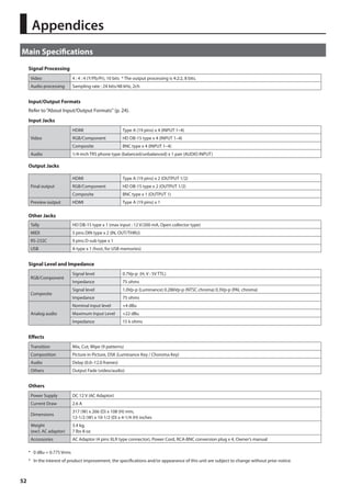
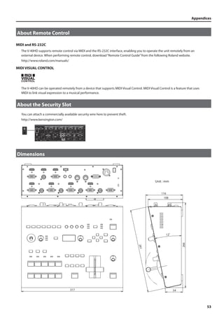
![Appendices
Troubleshooting
V-40HD does not boot up
54
Are the HDMI connectors on the OUTPUT 1/2 and the PVW OUT connected properly?
When HDMI outputs from any HDMI devices are connected to the OUTPUT 1/2 or the PVW OUT by mistake, the V-40HD may not
boot up.
Nothing is displayed on the preview monitor.
Does the connected monitor support a resolution and refresh rate of 1920 x 1080/60 Hz (progressive)?
Nothing is displayed if the monitor is not compatible. Also, nothing is displayed if the monitor does not support HDCP signals. If
you are making the connection using an HDMI-DVI conversion cable, go to the Output menu and select DVI-D in PVW Output.
Composite input is not output.
Is composite assigned as the source?
In the factory-default state, HDMI input is assigned. The assignment must be changed to composite input (p. 20).
Does the unit’s frame rate match with it of input signal?
If not, the signal does not come out.
Analog RGB input is not output.
Is RGB assigned as the source?
In the factory-default state, HDMI input is assigned. The assignment must be changed to analog RGB input (p. 19).
* The same operation is also necessary when using a conversion cable to make an analog-component connection.
Is the refresh rate 60 Hz or less?
If the refresh rate exceeds 60 Hz, the unit does not recognize the input signal.
HDMI input is not output.
Is HDMI assigned as the source?
If this is not assigned correctly, the signal cannot be detected.
Is the HDCP applied to the input signal?
If you are attempting to input the signal with HDCP, turn the HDCP setting on.
Output colors are not correct.
Has the setting for color space been made correctly?
• At the Input menu, set the channels correctly.
• At the Output menu, set the color space correctly.
Is the OUTPUT FORMAT setting is supported by the connected monitor ?
No output is made via the RGB/COMPONENT connectors of OUTPUT 1/2.
Has the setting for inputting HDCP signals been made?
When [HDCP] on the System menu is set to [ON], output via the RGB/COMPONENT connectors is stopped.
* Note, however, that HDMI output continues.
Is an interlace format selected as the output format?
If you are attemting to output from the RGB/COMPONENT connectors, select a progressive or RGB format.
No output is made via the COMPOSITE connector of OUTPUT 1.
Has the setting for inputting HDCP signals been made?
When [HDCP] on the System menu is set to [ON], as with output via the RGB/COMPONENT connectors, output via the COMPOSITE
connector of OUTPUT 1 is stopped.
Compositing with DSK is not possible.
Is the logo or text being input to the channel specified by [Source Channel] on the DSK menu?
Also adjust [TYPE] and [Level] on the DSK menu to appropriate values matched to the source.](https://image.slidesharecdn.com/v-40hde05w-140903070030-phpapp02/85/Multi-format-Video-Switcher-54-320.jpg)
![Appendices
55
Fading of DSK foreground image is not possible
Is CUT selected as the transition effect?
Is [Chroma 1] or [Chroma 2] is selected as [Type] of DSK?
If you are selecting one of above, the fade in/out of foreground image is disabled. Cut in/out is applied.
No audio is output via equipment connected to OUTPUT 1/2.
Has the correct source been selected using “HDMI Output Select” on the Audio menu?
Is “Main Volume” set too low?
Is the volume level of the connected monitor set too low?
Is the connected audio device is compatible with linear PCM?
The volume level of equipment connected to AUDIO INPUT is too low.
Could you be using a connection cable that contains a resistor?
Use a connection cable that does not contain a resistor.
Video and audio timing is out of sync.
Adjust [HDMI Audio Delay] and [Audio In Delay] on the Audio menu.
A USB memory device cannot be used.
Was the USB memory device formatted on the V-40HD?
A USB memory device that has not been formatted on this product cannot be used. Also, operation has been tested for commonly
available USB memory devices, but operation of all USB memory devices is not assured. Depending on the manufacturer and type
of the USB memory device, correct operation may not be possible.
Switching is not complete even when the video fader is moved.
Carry out calibration of the video fader. Move video fader all the way to either the front or the back, then go to the System menu
and select and execute [Video Fader Calibrate].
The panel indicators are too bright/dark.
Carry out dimmer adjustment. At the System menu, raise or lower the value of the [LED Dimmer] setting.
No labels are displayed on the preview monitor.
Has the setting for hiding labels been made?
Go to the System menu and select [PVW Label] to access the detailed setup screen, and change the setting for [Indicate] to [ON].
Nothing can be saved to MEMORY buttons.
Is memory protection turned on?
Go to the System menu and select [Memory Protect], and set it to [OFF].
No fade is applied to final output.
Is fade time set to zero?
Go to the System menu and select [Output Fade] to access the detailed setup screen, and make the setting for [Time]. No fade is
applied when this parameter is set to [0.0s].
A short black images appear while switching.
On the conditions below, a short black image is inserted between 2 video images if you directly switch the video pressing the
buttons in [A-BUS/PGM] section.
• When a direct switching operation is carried out while a logo/text is composited using the DSK function.
• [DSK] is selected as the dislay mode of preview monitor and [PST] is selected as the output source for OUTPUT 1/2.
• [DSK Source] is selected as the output source for OUTPUT 1/2.
A short black image is inserted the output if you carry out the operations below while you are compositing logo/text using the DSK.
• Switching of source channel for background or inset screen while you are using PinP and DSK.
• Switching of source channel while the transition effect is going on under the logo/text composited using the DSK.](https://image.slidesharecdn.com/v-40hde05w-140903070030-phpapp02/85/Multi-format-Video-Switcher-55-320.jpg)
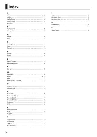


This document provides safety instructions and important notes for using the V-40HD video mixer. It outlines precautions for safe operation, proper placement, cleaning and maintenance, repairs, and use of USB memories. Key points include only using the supplied AC adapter, avoiding extreme temperatures and moisture, turning the unit off if an abnormality occurs, and backing up important data to external devices.


