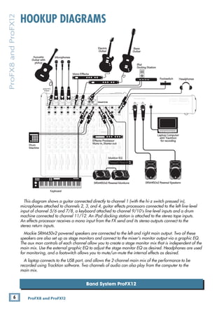
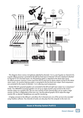
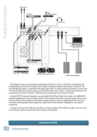
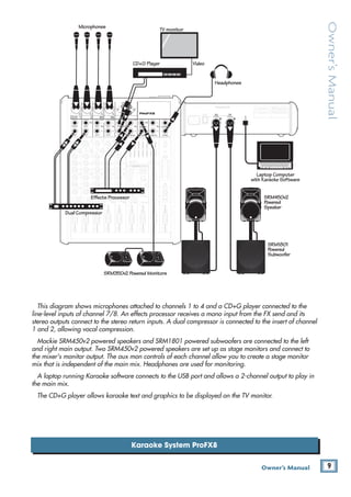
The document is an owner's manual for the ProFX8 and ProFX12 professional microphone/line mixers. It contains 3 pages of instructions and safety information for operating the mixers, including how to set levels on the mono, hybrid, and stereo channels, how to mix using the channel and main faders, how to use the USB connection to play and record audio, and important notes on powering up and shutting down the system safely. The manual provides concise directions for using the key features of the mixers while ensuring safe operation.
![12 ProFX8 and ProFX12
ProFX8
and
ProFX12
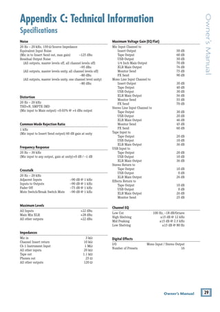
Rear Panel Features
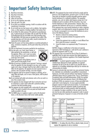
1. POWER CONNECTION
This is a standard 3-prong IEC AC power connector.
Securely connect the supplied detachable linecord here
and plug the other end into an AC outlet. The mixer has
a universal power supply that may accept any AC voltage
ranging from 100 VAC to 240 VAC. No need for voltage
select switches or step-up or step-down transformers;
it will work virtually anywhere in the world. It is less
susceptible to voltage sags or spikes than conventional
power supplies and provides greater electromagnetic
isolation and better protection against AC line noise.
2. POWER SWITCH
Press the top of this rocker switch to turn on the
mixer. The front panel power LED [32] will glow with
happiness...or at least it will if the mixer is plugged into
a suitable live AC mains supply.
Press the bottom of this switch to put the mixer into
standby mode. It will not function, but the circuits are
still live. To remove AC power, either turn off the AC
mains supply, or unplug the power cord from the mixer
and the AC mains supply.
As a general guide, turn on the mixer first,
before any external power amplifiers or
powered speakers, and turn it off last. This
will reduce the possibility of any turn-on or turn-off
thumps in the speakers.
3. XLR MAIN OUTS
These XLR connectors provide stereo line-level
signals from the main mix. Connect these to the
balanced inputs of the powered speakers, or to the
power amplifier powering the main speakers.
The main mix is the sum of all active channels
currently playing, including any 2-channel USB input
from the computer. How much of a channel that is
heard in the main mix is determined by that channel’s
fader [30].
MAIN
RIGHT
(BALANCED)
MAIN
LEFT
USB
(BALANCED)
8K
4K
2K
1K
500
250
125
15
15
10
10
5
5
0
15
15
10
10
5
5
0
TAPE
IN
ST RETURN MAIN OUT PHONES
FOOTSWITCH
PHONES
TAPE
OUT
L
R
L
(UNBALANCED)
R
STEREO GRAPHIC EQ
FX SEND
MID
2.5kHz
MID
2.5kHz
MID
2.5kHz
MID
2.5kHz
MID
2.5kHz
80Hz
LOW
U
+15
-15
U
+15
-15
U
+15
-15
LINE IN 4
INSERT
R
L
LOW CUT
100 Hz
U
GAIN
M
IC GAIN
U +50
-20dB +30dB
4
12kHz
HI
MID
2.5kHz
80Hz
LOW
U
+15
-15
U
+15
-15
U
+15
-15
12kHz
HI
MID
2.5kHz
80Hz
LOW
U
+15
-15
U
+15
-15
U
+15
-15
12kHz
HI
MID
2.5kHz
80Hz
LOW
U
+15
-15
U
+15
-15
U
+15
-15
12kHz
HI
PAN
AUX
U
+15
O
O
MON
FX
U
+15
O
O
R
L
PAN
AUX
U
+15
O
O
MON
FX
U
+15
O
O
R
L
PAN
AUX
U
+15
O
O
MON
FX
U
+15
O
O
R
L
PAN
AUX
U
+15
O
O
MON
FX
U
+15
O
O
80Hz
LOW
U
+15
-15
U
+15
-15
U
+15
-15
R
L
LOW CUT
100 Hz
12kHz
HI
PAN
AUX
U
+15
O
O
MON
FX
U
+15
O
O
80Hz
LOW
U
+15
-15
U
+15
-15
U
+15
-15
BAL /
UNBAL
(MONO) (MONO) (MONO) (MONO)
LINE IN 7
LINE IN 8
BAL /
UNBAL LINE IN 9
R
L
LOW CUT
100 Hz
GAIN
7/8
5/6
12kHz
HI
PAN
AUX
U
+15
O
O
MON
FX
U
+15
O
O
80Hz
LOW
U
+15
-15
U
+15
-15
U
+15
-15
R
L
MIC GAIN
U +50
GAIN
MIC GAIN
U +50
9/10
12kHz
HI
LEVEL
SET
LEVEL
SET
LEVEL
SET
LOW CUT
100 Hz
U
GAIN
M
IC GAIN
U +50
-20dB +30dB
LEVEL
SET
LEVEL
SET
LEVEL
SET
LOW CUT
100 Hz
U
GAIN
M
IC GAIN
U +50
-20dB +30dB
LOW CUT
100 Hz
U
GAIN
M
IC GAIN
U +50
-20dB +30dB
PAN
AUX
U
+15
O
O
MON
FX
U
+15
O
O
GAIN
MIC
MIC
MIC
MIC
MIC
MIC
80Hz
LOW
U
+15
-15
U
+15
-15
U
+15
-15
U
+20
-20
GAIN
U
+20
-20
R
L
11/12 ST RTN FX RTN
EQ
EQ
EQ
EQ EQ EQ EQ EQ
12kHz
HI
PAN
AUX
U
+15
O
O
MON
FX
U
+15
O
O
U
+15
FX TO MON
FX MASTER
U
+15
O
O O
O
dB
30
20
10
10
O
O
40
50
5
5
U
60
dB
30
20
10
10
O
O
40
50
5
5
U
60
dB
30
20
10
10
O
O
40
50
5
5
U
60
dB
30
20
10
10
O
O
40
50
5
5
U
60
dB
30
20
10
10
O
O
40
50
5
5
U
60
dB
30
20
10
10
O
O
40
50
5
5
U
60
dB
30
20
10
10
O
O
40
50
5
5
U
60
dB
30
20
10
10
O
O
40
50
5
5
U
60
dB
30
20
10
10
O
O
40
50
5
5
U
60
dB
30
20
10
10
O
O
40
50
5
5
U
60
dB
30
20
10
10
O
O
40
50
5
5
U
60
dB
30
20
10
10
O
O
40
50
5
5
U
60
L
R
(MONO)
LINE IN 5
LINE IN 6
BAL /
UNBAL
L
R
LINE IN 10
BAL /
UNBAL
L
R
LINE IN 11
LINE IN 12
BAL /
UNBAL
L
R
BAL /
UNBAL
L
R
BAL /
UNBAL
L
R
MON SEND
BAL /
UNBAL
BAL /
UNBAL
PRESETS
FX PRESETS
01 BRIGHT ROOM
02 WARM LOUNGE
03 SMALL STAGE
04 WARM THEATER
05 WARM HALL
06 CONCERT HALL
13 DELAY 1 (300ms)
14 DELAY 2 (380ms)
15 DELAY 3 (480ms)
16 REVERB + DLY (250ms)
07 PLATE REVERB
08 CATHEDRAL
09 CHORUS
10 CHORUS + REV
11 DOUBLER
12 TAPE SLAP
MON MAIN
4
LINE IN 3
INSERT
3
BAL /
UNBAL
3
LINE IN 2
INSERT
2
BAL /
UNBAL
BAL /
UNBAL
2
LINE/HI-Z IN 1
INSERT
1 5/6 7/8 9/10 11/12
POWER
ON
0dB=0dBu
MAIN
METERS
OL
4
6
3
10
15
7
10
20
30
0
2
BREAK
(MUTES ALL CHANNELS)
PHANTOM
POWER
POWER
O
O +10
U
TAPE LEVEL
O
O +20
U
USB THRU
LINE
HI-Z
O
O MAX
1
OL OL OL OL OL OL OL OL OL
OL
MAIN MIX
MON
EQ IN
BYPASS
R
L
INPUT LEVEL
USB
MUTE
MUTE MUTE MUTE MUTE MUTE MUTE MUTE MUTE MUTE
48V
The XLR outputs are 6 dB higher output than
the 1/4" TRS main outputs [14]. Balanced
connections offer better immunity to external
noise (specifically, hum and buzz) than unbalanced
connections. Because of this, it is the preferred
interconnect method, especially where very long
lengths of cable are being used.
4. USB PORT
The USB serial I/O interface allows digital audio to
transfer to and from a computer.
The interface provides two audio outputs to the
computer:
• Main mix output, left and right. These output
signals are independent of any adjustments
made to the main fader [47] and graphic EQ
[36]. This allows you to easily record live
performance directly to a laptop.
• The USB thru switch [40] allows you to also
include the output from your computer in your
recording. See page 23 for more details of this
switch.
The computer may also playback two channels into
the mixer via the USB interface:
• Left and right signals from the computer are
added to the main mix. The USB input level
control [39] allows you to adjust the level of
the incoming audio from the computer being
added to the main mix.
1 2
3 4](https://image.slidesharecdn.com/profx812om-230216122837-d5649219/85/ProFX8_12_OM-pdf-12-320.jpg)
![13
Owner’s Manual
Owner’s
Manual
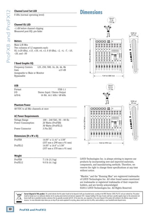
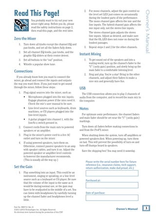
Front Panel Features
Connection Section
This is where to plug things in: microphones, line-
level
instruments and effects, headphones, and the
ultimate destination for your sound: PA system, stage
monitors, effects processors, CD
player/recorder, etc.
See Appendix B for further details and drawings of
the connectors to use with the ProFX mixer.
5. MIC INPUTS
We use phantom-powered, balanced
microphone
inputs just like the big studio mega-consoles for
exactly the same reason: This kind of circuit is
excellent at rejecting hum and noise. You can plug
in almost any kind of mic that has a standard
XLR
male mic connector.
Professional ribbon, dynamic and condenser mics will
all sound excellent through these inputs. The ProFX
mixer’s mic inputs will handle any kind of mic level
tossed at them without overloading. Be sure to perform
the gain-setting procedure mentioned on page 3.
PHANTOM POWER
Most modern professional condenser mics
require phantom power which lets the mixer send
low-current DC voltage to the mic’s electronics through
the same wires that carry audio. (Semi-pro condenser
mics often have batteries to accomplish the same
thing.) “Phantom” owes its name to an ability to be
“unseen” by dynamic mics (Shure SM57/SM58, for
instance), which don’t need
external power and aren’t
affected by it, anyway.
The ProFX mixer’s phantom power is globally
controlled by the phantom power switch [31]. (This
means that phantom power for all mic inputs is turned
on and off together.)
Never plug
single-ended (unbalanced)
micro
phones or ribbon microphones into the
mic input jacks if phantom power is on. Do
not plug instrument outputs into the mic input jacks
with phantom power on
unless you know for certain it is
safe to do so.
6. LINE/HI-Z SWITCH
To connect a guitar directly to the mixer without
using a DI Box, press this switch in first; then connect
the output from the guitar to channel 1's 1⁄4" TRS
input [7]. The input impedance is optimized for direct
connection and high-frequency fidelity is assured.
In the out position, channel 1's 1⁄4" TRS input
becomes a line input just like the other mono line
inputs [8].
To use guitars or other instruments on other
channels, you will need to use an external DI box
first. Without the DI box – or if this switch is not
pressed in – guitars may sound dull and muddy.
7. LINE/HI-Z INPUT (Channel 1 only)
This 1/4" jack shares circuitry (but not phantom
power) with the mic preamp and may be driven by
balanced or unbalanced sources.
To connect a balanced line to this input, use a 1⁄4"
Tip-Ring-Sleeve (TRS) plug.
To connect an unbalanced line to this
input, use a 1⁄4"
mono (TS) phone plug or
instrument cable.
This line-level input may also accept instrument-level
signals if the hi-z switch [6] is pressed in. This allows
you to connect guitars directly into channel 1 without
the need for a DI box.
8K
4K
2K
1K
500
250
125
15
15
10
10
5
5
0
15
15
10
10
5
5
0
TAPE
IN
ST RETURN MAIN OUT PHONES
FOOTSWITCH
PHONES
TAPE
OUT
L
R
L
(UNBALANCED)
R
STEREO GRAPHIC EQ
FX SEND
MID
2.5kHz
MID
2.5kHz
MID
2.5kHz
MID
2.5kHz
MID
2.5kHz
80Hz
LOW
U
+15
-15
U
+15
-15
U
+15
-15
LINE IN 4
INSERT
R
L
LOW CUT
100 Hz
U
GAIN
M
IC GAIN
U +50
-20dB +30dB
4
12kHz
HI
MID
2.5kHz
80Hz
LOW
U
+15
-15
U
+15
-15
U
+15
-15
12kHz
HI
MID
2.5kHz
80Hz
LOW
U
+15
-15
U
+15
-15
U
+15
-15
12kHz
HI
MID
2.5kHz
80Hz
LOW
U
+15
-15
U
+15
-15
U
+15
-15
12kHz
HI
PAN
AUX
U
+15
O
O
MON
FX
U
+15
O
O
R
L
PAN
AUX
U
+15
O
O
MON
FX
U
+15
O
O
R
L
PAN
AUX
U
+15
O
O
MON
FX
U
+15
O
O
R
L
PAN
AUX
U
+15
O
O
MON
FX
U
+15
O
O
80Hz
LOW
U
+15
-15
U
+15
-15
U
+15
-15
R
L
LOW CUT
100 Hz
12kHz
HI
PAN
AUX
U
+15
O
O
MON
FX
U
+15
O
O
80Hz
LOW
U
+15
-15
U
+15
-15
U
+15
-15
BAL /
UNBAL
(MONO) (MONO) (MONO) (MONO)
LINE IN 7
LINE IN 8
BAL /
UNBAL LINE IN 9
R
L
LOW CUT
100 Hz
GAIN
7/8
5/6
12kHz
HI
PAN
AUX
U
+15
O
O
MON
FX
U
+15
O
O
80Hz
LOW
U
+15
-15
U
+15
-15
U
+15
-15
R
L
MIC GAIN
U +50
GAIN
MIC GAIN
U +50
9/10
12kHz
HI
LEVEL
SET
LEVEL
SET
LEVEL
SET
LOW CUT
100 Hz
U
GAIN
M
IC GAIN
U +50
-20dB +30dB
LEVEL
SET
LEVEL
SET
LEVEL
SET
LOW CUT
100 Hz
U
GAIN
M
IC GAIN
U +50
-20dB +30dB
LOW CUT
100 Hz
U
GAIN
M
IC GAIN
U +50
-20dB +30dB
PAN
AUX
U
+15
O
O
MON
FX
U
+15
O
O
GAIN
MIC
MIC
MIC
MIC
MIC
MIC
80Hz
LOW
U
+15
-15
U
+15
-15
U
+15
-15
U
+20
-20
GAIN
U
+20
-20
R
L
11/12 ST RTN FX RTN
EQ
EQ
EQ
EQ EQ EQ EQ EQ
12kHz
HI
PAN
AUX
U
+15
O
O
MON
FX
U
+15
O
O
U
+15
FX TO MON
FX MASTER
U
+15
O
O O
O
dB
30
20
10
10
O
O
40
50
5
5
U
60
dB
30
20
10
10
O
O
40
50
5
5
U
60
dB
30
20
10
10
O
O
40
50
5
5
U
60
dB
30
20
10
10
O
O
40
50
5
5
U
60
dB
30
20
10
10
O
O
40
50
5
5
U
60
dB
30
20
10
10
O
O
40
50
5
5
U
60
dB
30
20
10
10
O
O
40
50
5
5
U
60
dB
30
20
10
10
O
O
40
50
5
5
U
60
dB
30
20
10
10
O
O
40
50
5
5
U
60
dB
30
20
10
10
O
O
40
50
5
5
U
60
dB
30
20
10
10
O
O
40
50
5
5
U
60
dB
30
20
10
10
O
O
40
50
5
5
U
60
L
R
(MONO)
LINE IN 5
LINE IN 6
BAL /
UNBAL
L
R
LINE IN 10
BAL /
UNBAL
L
R
LINE IN 11
LINE IN 12
BAL /
UNBAL
L
R
BAL /
UNBAL
L
R
BAL /
UNBAL
L
R
MON SEND
BAL /
UNBAL
BAL /
UNBAL
PRESETS
FX PRESETS
01 BRIGHT ROOM
02 WARM LOUNGE
03 SMALL STAGE
04 WARM THEATER
05 WARM HALL
06 CONCERT HALL
13 DELAY 1 (300ms)
14 DELAY 2 (380ms)
15 DELAY 3 (480ms)
16 REVERB + DLY (250ms)
07 PLATE REVERB
08 CATHEDRAL
09 CHORUS
10 CHORUS + REV
11 DOUBLER
12 TAPE SLAP
MON MAIN
4
LINE IN 3
INSERT
3
BAL /
UNBAL
3
LINE IN 2
INSERT
2
BAL /
UNBAL
BAL /
UNBAL
2
LINE/HI-Z IN 1
INSERT
1 5/6 7/8 9/10 11/12
0dB=0dBu
MAIN
METERS
OL
4
6
3
10
15
7
10
20
30
0
2
BREAK
(MUTES ALL CHANNELS)
PHANTOM
POWER
POWER
O
O +10
U
TAPE LEVEL
O
O +20
U
USB THRU
LINE
HI-Z
O
O MAX
1
OL OL OL OL OL OL OL OL OL
OL
MAIN MIX
MON
EQ IN
BYPASS
R
L
INPUT LEVEL
USB
MUTE
MUTE MUTE MUTE MUTE MUTE MUTE MUTE MUTE MUTE
48V
6
5
7
10
8 8 8
9 9 9
10 10 10
9](https://image.slidesharecdn.com/profx812om-230216122837-d5649219/85/ProFX8_12_OM-pdf-13-320.jpg)
![14 ProFX8 and ProFX12
ProFX8
and
ProFX12
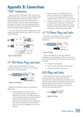
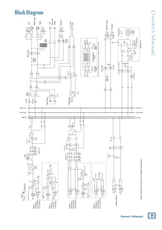
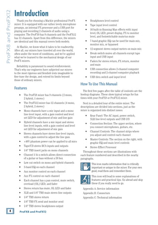
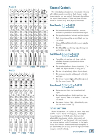
The insert point is after the gain control [19], level
set LED [20] and low cut switch [21], but before the
channel EQ [22-24] and fader [30]. The channel signal
may go out of the insert jack to an external device, be
processed (or whatever) and come back in on the same
insert jack. To do this requires a special insert cable
that must be wired thusly:
Tip = send (output to effects device)
Ring = return (input from effects device)
Sleeve = common ground
Insert jacks may be used as channel direct outputs;
post-gain, and pre-EQ. See the connector section on
page 28 (figure F) showing three ways to use insert
connections.
11. STEREO RETURN
This is where to connect the outputs of parallel
effects devices (or extra audio sources). The circuits
will handle stereo or mono, balanced or unbalanced
signals. They may be used with just about any pro or
semi-pro
effects
device or line-level source on the
market. The signals coming into these inputs may be
adjusted using the stereo return fader [44] before
passing onto the main mix bus (see page 23). Signals
coming in here may also be quickly muted with the
mute switch [43], and the OL LED [42] will illuminate
if the incoming signal is too high.
Stereo Device: If using a stereo parallel effects device
(two cords), use stereo return left and right.
Mono Device: If using an effects device with a mono
output (one cord), plug that into the stereo return left/
mono, and leave the right unplugged. The signal will be
sent to both sides, magically appearing in the center as
a mono signal.
8. MONO LINE INPUTS
These 1/4" jacks share circuitry (but not phantom
power) with the mic preamps and may be driven by
balanced or unbalanced sources.
To connect balanced lines to these inputs, use a
1⁄4" Tip-Ring-Sleeve (TRS) plug.
To connect unbalanced lines to these
inputs, use a
1⁄4" mono (TS) phone plug or
instrument cable.
If using a stereo source, and the stereo
and hybrid channels are in use, utilize two
mono channels instead. Traditionally, an
odd-numbered channel receives the left signal. For
example, feed the ProFX mixer a stereo signal by
inserting the device’s left output plug into the
channel 1 jack (panned fully left) and its right output
plug into the channel 2 jack (panned fully right).
9. STEREO LINE INPUTS
These 1/4" jacks may be driven by stereo or mono,
balanced or unbalanced sources. They may be used
with just about any professional or semi-pro
instrument, effect or tape player.
To connect balanced lines to these inputs, use a 1⁄4"
Tip-Ring-Sleeve (TRS) plug.
To connect unbalanced lines to these
inputs, use a
1⁄4" mono (TS) phone plug or
instrument cable.
If using just a mono source, plug it into the left input
(labeled mono) and the signal will appear (as if by
magic) equally on the left and right of the main mix.
10. CHANNEL INSERT
These unbalanced 1/4" jacks are for connecting serial
effects processors such as compressors, equalizers,
de-essers, or filters.
We’ve included inserts for just the mono channels.
If using this kind of processing on other channels,
simply patch through the
processor before plugging
into the ProFX mixer.
8K
4K
2K
1K
500
250
125
15
15
10
10
5
5
0
15
15
10
10
5
5
0
TAPE
IN
ST RETURN MAIN OUT PHONES
FOOTSWITCH
PHONES
TAPE
OUT
L
R
L
(UNBALANCED)
R
STEREO GRAPHIC EQ
FX SEND
MID
2.5kHz
MID
2.5kHz
MID
2.5kHz
MID
2.5kHz
MID
2.5kHz
80Hz
LOW
U
+15
-15
U
+15
-15
U
+15
-15
LINE IN 4
INSERT
R
L
LOW CUT
100 Hz
U
GAIN
M
IC GAIN
U +50
-20dB +30dB
4
12kHz
HI
MID
2.5kHz
80Hz
LOW
U
+15
-15
U
+15
-15
U
+15
-15
12kHz
HI
MID
2.5kHz
80Hz
LOW
U
+15
-15
U
+15
-15
U
+15
-15
12kHz
HI
MID
2.5kHz
80Hz
LOW
U
+15
-15
U
+15
-15
U
+15
-15
12kHz
HI
PAN
AUX
U
+15
O
O
MON
FX
U
+15
O
O
R
L
PAN
AUX
U
+15
O
O
MON
FX
U
+15
O
O
R
L
PAN
AUX
U
+15
O
O
MON
FX
U
+15
O
O
R
L
PAN
AUX
U
+15
O
O
MON
FX
U
+15
O
O
80Hz
LOW
U
+15
-15
U
+15
-15
U
+15
-15
R
L
LOW CUT
100 Hz
12kHz
HI
PAN
AUX
U
+15
O
O
MON
FX
U
+15
O
O
80Hz
LOW
U
+15
-15
U
+15
-15
U
+15
-15
BAL /
UNBAL
(MONO) (MONO) (MONO) (MONO)
LINE IN 7
LINE IN 8
BAL /
UNBAL LINE IN 9
R
L
LOW CUT
100 Hz
GAIN
7/8
5/6
12kHz
HI
PAN
AUX
U
+15
O
O
MON
FX
U
+15
O
O
80Hz
LOW
U
+15
-15
U
+15
-15
U
+15
-15
R
L
MIC GAIN
U +50
GAIN
MIC GAIN
U +50
9/10
12kHz
HI
LEVEL
SET
LEVEL
SET
LEVEL
SET
LOW CUT
100 Hz
U
GAIN
M
IC GAIN
U +50
-20dB +30dB
LEVEL
SET
LEVEL
SET
LEVEL
SET
LOW CUT
100 Hz
U
GAIN
M
IC GAIN
U +50
-20dB +30dB
LOW CUT
100 Hz
U
GAIN
M
IC GAIN
U +50
-20dB +30dB
PAN
AUX
U
+15
O
O
MON
FX
U
+15
O
O
GAIN
MIC
MIC
MIC
MIC
MIC
MIC
80Hz
LOW
U
+15
-15
U
+15
-15
U
+15
-15
U
+20
-20
GAIN
U
+20
-20
R
L
11/12 ST RTN FX RTN
EQ
EQ
EQ
EQ EQ EQ EQ EQ
12kHz
HI
PAN
AUX
U
+15
O
O
MON
FX
U
+15
O
O
U
+15
FX TO MON
FX MASTER
U
+15
O
O O
O
dB
30
20
10
10
O
O
40
50
5
5
U
60
dB
30
20
10
10
O
O
40
50
5
5
U
60
dB
30
20
10
10
O
O
40
50
5
5
U
60
dB
30
20
10
10
O
O
40
50
5
5
U
60
dB
30
20
10
10
O
O
40
50
5
5
U
60
dB
30
20
10
10
O
O
40
50
5
5
U
60
dB
30
20
10
10
O
O
40
50
5
5
U
60
dB
30
20
10
10
O
O
40
50
5
5
U
60
dB
30
20
10
10
O
O
40
50
5
5
U
60
dB
30
20
10
10
O
O
40
50
5
5
U
60
dB
30
20
10
10
O
O
40
50
5
5
U
60
dB
30
20
10
10
O
O
40
50
5
5
U
60
L
R
(MONO)
LINE IN 5
LINE IN 6
BAL /
UNBAL
L
R
LINE IN 10
BAL /
UNBAL
L
R
LINE IN 11
LINE IN 12
BAL /
UNBAL
L
R
BAL /
UNBAL
L
R
BAL /
UNBAL
L
R
MON SEND
BAL /
UNBAL
BAL /
UNBAL
PRESETS
FX PRESETS
01 BRIGHT ROOM
02 WARM LOUNGE
03 SMALL STAGE
04 WARM THEATER
05 WARM HALL
06 CONCERT HALL
13 DELAY 1 (300ms)
14 DELAY 2 (380ms)
15 DELAY 3 (480ms)
16 REVERB + DLY (250ms)
07 PLATE REVERB
08 CATHEDRAL
09 CHORUS
10 CHORUS + REV
11 DOUBLER
12 TAPE SLAP
MON MAIN
4
LINE IN 3
INSERT
3
BAL /
UNBAL
3
LINE IN 2
INSERT
2
BAL /
UNBAL
BAL /
UNBAL
2
LINE/HI-Z IN 1
INSERT
1 5/6 7/8 9/10 11/12
0dB=0dBu
MAIN
METERS
OL
4
6
3
10
15
7
10
20
30
0
2
BREAK
(MUTES ALL CHANNELS)
PHANTOM
POWER
POWER
O
O +10
U
TAPE LEVEL
O
O +20
U
USB THRU
LINE
HI-Z
O
O MAX
1
OL OL OL OL OL OL OL OL OL
OL
MAIN MIX
MON
EQ IN
BYPASS
R
L
INPUT LEVEL
USB
MUTE
MUTE MUTE MUTE MUTE MUTE MUTE MUTE MUTE MUTE
48V
6
5
7
10
8 8 8
9 9 9
10 10 10
9 11
12
14
15
16
13
5 5 5 5 5
17 18
“tip”
This plug connects to one of the
mixer’s Channel Insert jacks.
“ring”
tip
ring
sleeve
SEND to processor
RETURN from processor
(TRS plug)](https://image.slidesharecdn.com/profx812om-230216122837-d5649219/85/ProFX8_12_OM-pdf-14-320.jpg)
![15
Owner’s Manual
Owner’s
Manual
12. MON SEND
Stage monitors allow the talented musicians to hear
themselves clearly on stage, and this can often be a
good thing. The monitor mix may be carefully adjusted
in level using the aux mon controls [25]. These tap a
portion of each channel's signal to provide a 1/4" TRS
output here to feed external stage monitors. These
could either be passive stage monitors powered by an
external amplifier, or powered stage monitors with their
own amplifier built in.
The monitor signal is the sum (mix) of all the
channels whose aux mon control is set to more than
minimum. If they want “more me, and less Keith,” you
should turn up their channel's aux mon control, and
turn down Keith's.
The overall output level may be adjusted with the
monitor fader [46] and its EQ tweaked with the graphic
EQ [36] if the main mix/mon switch [37] is pressed in.
Alternatively, an external graphic EQ may be added
between this output and the powered monitors. This
allows you to adjust the EQ and minimize the chance of
feedback from nearby microphones.
The monitor output is not affected by the main fader
[47] or the channel faders [30]. This allows you to set
up the monitor mix and level just right, and not have it
change when a channel fader or the main mix fader is
adjusted. This is known as “pre-fader.”
13. FX SEND
This 1/4" TRS line-level output may be used to feed
an external effects processor (FX), such as a nice
sound effect or delay unit. The output from this jack
is an exact copy of what goes into the internal FX
processor, being the careful mix of all channels whose
aux FX control [26] is turned to more than minimum.
(The processed output of the internal FX does not
come out of this output, but is added internally to the
main mix or monitor mix.)
The overall output level may be adjusted with the
FX master knob [51]. (This knob also effects the
level going into the internal FX.)
The output is “post-fader,” so any changes to the
channel faders [30] will also affect the level going to
the external processor.
The processed output from the effects processor is
usually returned to the stereo returns [11] or a spare
channel where you may carefully mix the original
unprocessed channel (dry) and the processed channel
(wet). Altering the original channel fader increases
both the wet and dry signals and keeps them at the
same delicate ratio. (For example, the reverb remains
at the same level relative to the original.)
14. 1/4" MAIN OUTS
These outputs feed the main mix out into the waiting
world. Amplifiers may be fed this way or through the
XLR main outputs [3].
To use these outputs to drive balanced inputs,
connect 1⁄4" TRS (Tip–Ring–Sleeve) phone plugs like
this:
Tip = + (hot)
Ring = –(cold)
Sleeve = Ground
To use these outputs to drive unbalanced inputs,
connect 1⁄4" TS (Tip-Sleeve) phone plugs like this:
Tip = + (hot)
Sleeve = Ground
15. FX FOOTSWITCH
This 1/4" TRS connector is where to connect a
footswitch. This will allow you to easily mute or
un-mute the internal effects, while stamping your
foot and looking like you were mad about something.
Any latching one-button on/off footswitch will work.
If the internal effects have already been muted with
the internal FX mute switch [50], then the footswitch
has no effect, but you can still stamp your foot and pout
if that helps any. Cultivate that bad-boy image.
16. PHONES
This 1⁄4" TRS stereo jack will drive any standard
headphone to very loud levels. The wiring follows
standard conventions:
Tip = Left channel
Ring = Right channel
Sleeve = Common ground
The headphones output is the stereo main mix, not
affected by the main fader [47], or the graphic EQ [36].
Warning: When we say the headphone
output is loud, we’re not kidding. It can cause
permanent ear damage. Even intermediate
levels may be painfully loud with some earphones. Be
careful! Always turn the phones level control [41] all
the way down before connecting headphones, adding
new sources, or making any other changes. Keep it down
until you’ve put the phones on. Then turn it up slowly.](https://image.slidesharecdn.com/profx812om-230216122837-d5649219/85/ProFX8_12_OM-pdf-15-320.jpg)
![16 ProFX8 and ProFX12
ProFX8
and
ProFX12
17. TAPE INPUT
These stereo unbalanced RCA inputs are designed
to work with semi-pro as well as pro player/recorders.
They may also be connected to any standard source with
an unbalanced line-level output, such as a CD or DVD
player, iPod, and so on.
Connect the source’s line-level outputs here using
good quality hi-fi (RCA) cables.
These may be used with a tape or CD player to feed
music to a PA system between sets when the break
switch [34] is engaged. The level coming into the mixer
may be adjusted with the tape level knob [35]. For
example, press the break switch to mute all channels at
once, then play the tape or CD player and bring up its
level slowly.
18. TAPE OUTPUT
These stereo unbalanced RCA outputs allow you to
record the main stereo mix onto a tape deck, hard disk
recorder, automatic CD burner, computer, etc.
This allows you to make a recording for posterity/
archive/legal purposes whenever the band gets back
together again.
The tape output is the stereo main mix, not affected
by the main fader [47], or the graphic EQ [36].
8K
4K
2K
1K
500
250
125
15
15
10
10
5
5
0
15
15
10
10
5
5
0
TAPE
IN
ST RETURN MAIN OUT PHONES
FOOTSWITCH
PHONES
TAPE
OUT
L
R
L
(UNBALANCED)
R
STEREO GRAPHIC EQ
FX SEND
MID
2.5kHz
MID
2.5kHz
MID
2.5kHz
MID
2.5kHz
MID
2.5kHz
80Hz
LOW
U
+15
-15
U
+15
-15
U
+15
-15
LINE IN 4
INSERT
R
L
LOW CUT
100 Hz
U
GAIN
M
IC GAIN
U +50
-20dB +30dB
4
12kHz
HI
MID
2.5kHz
80Hz
LOW
U
+15
-15
U
+15
-15
U
+15
-15
12kHz
HI
MID
2.5kHz
80Hz
LOW
U
+15
-15
U
+15
-15
U
+15
-15
12kHz
HI
MID
2.5kHz
80Hz
LOW
U
+15
-15
U
+15
-15
U
+15
-15
12kHz
HI
PAN
AUX
U
+15
O
O
MON
FX
U
+15
O
O
R
L
PAN
AUX
U
+15
O
O
MON
FX
U
+15
O
O
R
L
PAN
AUX
U
+15
O
O
MON
FX
U
+15
O
O
R
L
PAN
AUX
U
+15
O
O
MON
FX
U
+15
O
O
80Hz
LOW
U
+15
-15
U
+15
-15
U
+15
-15
R
L
LOW CUT
100 Hz
12kHz
HI
PAN
AUX
U
+15
O
O
MON
FX
U
+15
O
O
80Hz
LOW
U
+15
-15
U
+15
-15
U
+15
-15
BAL /
UNBAL
(MONO) (MONO) (MONO) (MONO)
LINE IN 7
LINE IN 8
BAL /
UNBAL LINE IN 9
R
L
LOW CUT
100 Hz
GAIN
7/8
5/6
12kHz
HI
PAN
AUX
U
+15
O
O
MON
FX
U
+15
O
O
80Hz
LOW
U
+15
-15
U
+15
-15
U
+15
-15
R
L
MIC GAIN
U +50
GAIN
MIC GAIN
U +50
9/10
12kHz
HI
LEVEL
SET
LEVEL
SET
LEVEL
SET
LOW CUT
100 Hz
U
GAIN
M
IC GAIN
U +50
-20dB +30dB
LEVEL
SET
LEVEL
SET
LEVEL
SET
LOW CUT
100 Hz
U
GAIN
M
IC GAIN
U +50
-20dB +30dB
LOW CUT
100 Hz
U
GAIN
M
IC GAIN
U +50
-20dB +30dB
PAN
AUX
U
+15
O
O
MON
FX
U
+15
O
O
GAIN
MIC
MIC
MIC
MIC
MIC
MIC
80Hz
LOW
U
+15
-15
U
+15
-15
U
+15
-15
U
+20
-20
GAIN
U
+20
-20
R
L
11/12 ST RTN FX RTN
EQ
EQ
EQ
EQ EQ EQ EQ EQ
12kHz
HI
PAN
AUX
U
+15
O
O
MON
FX
U
+15
O
O
U
+15
FX TO MON
FX MASTER
U
+15
O
O O
O
dB
30
20
10
10
O
O
40
50
5
5
U
60
dB
30
20
10
10
O
O
40
50
5
5
U
60
dB
30
20
10
10
O
O
40
50
5
5
U
60
dB
30
20
10
10
O
O
40
50
5
5
U
60
dB
30
20
10
10
O
O
40
50
5
5
U
60
dB
30
20
10
10
O
O
40
50
5
5
U
60
dB
30
20
10
10
O
O
40
50
5
5
U
60
dB
30
20
10
10
O
O
40
50
5
5
U
60
dB
30
20
10
10
O
O
40
50
5
5
U
60
dB
30
20
10
10
O
O
40
50
5
5
U
60
dB
30
20
10
10
O
O
40
50
5
5
U
60
dB
30
20
10
10
O
O
40
50
5
5
U
60
L
R
(MONO)
LINE IN 5
LINE IN 6
BAL /
UNBAL
L
R
LINE IN 10
BAL /
UNBAL
L
R
LINE IN 11
LINE IN 12
BAL /
UNBAL
L
R
BAL /
UNBAL
L
R
BAL /
UNBAL
L
R
MON SEND
BAL /
UNBAL
BAL /
UNBAL
PRESETS
FX PRESETS
01 BRIGHT ROOM
02 WARM LOUNGE
03 SMALL STAGE
04 WARM THEATER
05 WARM HALL
06 CONCERT HALL
13 DELAY 1 (300ms)
14 DELAY 2 (380ms)
15 DELAY 3 (480ms)
16 REVERB + DLY (250ms)
07 PLATE REVERB
08 CATHEDRAL
09 CHORUS
10 CHORUS + REV
11 DOUBLER
12 TAPE SLAP
MON MAIN
4
LINE IN 3
INSERT
3
BAL /
UNBAL
3
LINE IN 2
INSERT
2
BAL /
UNBAL
BAL /
UNBAL
2
LINE/HI-Z IN 1
INSERT
1 5/6 7/8 9/10 11/12
0dB=0dBu
MAIN
METERS
OL
4
6
3
10
15
7
10
20
30
0
2
BREAK
(MUTES ALL CHANNELS)
PHANTOM
POWER
POWER
O
O +10
U
TAPE LEVEL
O
O +20
U
USB THRU
LINE
HI-Z
O
O MAX
1
OL OL OL OL OL OL OL OL OL
OL
MAIN MIX
MON
EQ IN
BYPASS
R
L
INPUT LEVEL
USB
MUTE
MUTE MUTE MUTE MUTE MUTE MUTE MUTE MUTE MUTE
48V
17 18](https://image.slidesharecdn.com/profx812om-230216122837-d5649219/85/ProFX8_12_OM-pdf-16-320.jpg)
![18 ProFX8 and ProFX12
ProFX8
and
ProFX12
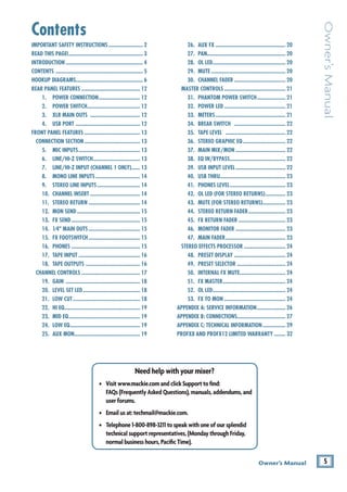
For hybrid channels (mic input and
stereo line input), the gain control just
affects the microphone input.
For stereo channels (no mic input) the
gain control just affects the line-level
inputs, with 20 dB of gain, and 20 dB of
attenuation. There is no level set LED.
20. LEVEL SET LED
These LEDs are used with the gain control [19] to set
the channel preamplifier gain just right for each source.
If one or more channels are distorting, check the level
set LEDs. If they are on continuously, turn down the
gain.
21. LOW CUT
Each channel with a mic input has a low cut switch
that cuts the bass frequencies below 100 Hz, at a rate of
18 dB per octave. All mic inputs are affected, as well as
the line inputs of the mono channels.
We recommend using low cut on
every microphone
application except kick drum, bass guitar, and bassy
synth patches. These aside, there isn’t much down there
that you want to hear, and filtering it out makes the low
stuff you do want much more crisp and tasty. Not only
that, low cut can help reduce the possibility of feedback
in live situations and help to conserve the amplifier
power.
19. GAIN
If you haven’t already, please read the gain-setting
procedure on page 3. The gain adjustment allows the
various source signals from the outside world to be
adjusted to the same optimal internal operating levels.
Setting the gain correctly will ensure that the pre-
amplifier’s gain is not too high, where distortion could
occur, and not too low, where the quieter, exquisitely-
delicate passages might be lost in background noise.
For mono channels (mic input with a
mono line input), the gain knob adjusts
the input sensitivity of the mic and line
inputs.
Adjust the gain control so the level set LEDs [20]
illuminate occasionally during the louder moments and
are off during the quieter moments.
If the signal comes through the mic XLR jack, there
will be 0 dB of gain (“U” for unity) with the knob fully
down, ramping to 50 dB of gain fully up.
Through the 1⁄4" mono input, there is 20 dB of
attenuation fully down and 30 dB of gain fully up,
with a “U” (unity gain) mark at 12:00. This 20 dB of
attenuation can be very handy when
inserting a very
hot signal, need to add a lot of EQ boost, or both.
Without this
“virtual pad,” this
scenario might lead
to channel clipping.
8K
4K
2K
1K
500
250
125
15
15
10
10
5
5
0
15
15
10
10
5
5
0
ST RETURN MAIN OUT PHONES
FOOTSWITCH
PHONES
STEREO GRAPHIC EQ
FX SEND
MID
2.5kHz
MID
2.5kHz
MID
2.5kHz
MID
2.5kHz
MID
2.5kHz
80Hz
LOW
U
+15
-15
U
+15
-15
U
+15
-15
LINE IN 4
INSERT
R
L
LOW CUT
100 Hz
U
GAIN
M
IC GAIN
U +50
-20dB +30dB
4
12kHz
HI
MID
2.5kHz
80Hz
LOW
U
+15
-15
U
+15
-15
U
+15
-15
12kHz
HI
MID
2.5kHz
80Hz
LOW
U
+15
-15
U
+15
-15
U
+15
-15
12kHz
HI
MID
2.5kHz
80Hz
LOW
U
+15
-15
U
+15
-15
U
+15
-15
12kHz
HI
PAN
AUX
U
+15
O
O
MON
FX
U
+15
O
O
R
L
PAN
AUX
U
+15
O
O
MON
FX
U
+15
O
O
R
L
PAN
AUX
U
+15
O
O
MON
FX
U
+15
O
O
R
L
PAN
AUX
U
+15
O
O
MON
FX
U
+15
O
O
80Hz
LOW
U
+15
-15
U
+15
-15
U
+15
-15
R
L
LOW CUT
100 Hz
12kHz
HI
PAN
AUX
U
+15
O
O
MON
FX
U
+15
O
O
80Hz
LOW
U
+15
-15
U
+15
-15
U
+15
-15
LINE IN 7
LINE IN 8
UNBAL LINE IN 9
R
L
LOW CUT
100 Hz
GAIN
7/8
5/6
12kHz
HI
PAN
AUX
U
+15
O
O
MON
FX
U
+15
O
O
80Hz
LOW
U
+15
-15
U
+15
-15
U
+15
-15
R
L
MIC GAIN
U +50
GAIN
MIC GAIN
U +50
9/10
12kHz
HI
LEVEL
SET
LEVEL
SET
LEVEL
SET
LOW CUT
100 Hz
U
GAIN
M
IC GAIN
U +50
-20dB +30dB
LEVEL
SET
LEVEL
SET
LEVEL
SET
LOW CUT
100 Hz
U
GAIN
M
IC GAIN
U +50
-20dB +30dB
LOW CUT
100 Hz
U
GAIN
M
IC GAIN
U +50
-20dB +30dB
PAN
AUX
U
+15
O
O
MON
FX
U
+15
O
O
GAIN
80Hz
LOW
U
+15
-15
U
+15
-15
U
+15
-15
U
+20
-20
GAIN
U
+20
-20
R
L
11/12 ST RTN FX RTN
EQ
EQ
EQ
EQ EQ EQ EQ EQ
12kHz
HI
PAN
AUX
U
+15
O
O
MON
FX
U
+15
O
O
U
+15
FX TO MON
FX MASTER
U
+15
O
O O
O
dB
30
20
10
10
O
O
40
50
5
5
U
60
dB
30
20
10
10
O
O
40
50
5
5
U
60
dB
30
20
10
10
O
O
40
50
5
5
U
60
dB
30
20
10
10
O
O
40
50
5
5
U
60
dB
30
20
10
10
O
O
40
50
5
5
U
60
dB
30
20
10
10
O
O
40
50
5
5
U
60
dB
30
20
10
10
O
O
40
50
5
5
U
60
dB
30
20
10
10
O
O
40
50
5
5
U
60
dB
30
20
10
10
O
O
40
50
5
5
U
60
dB
30
20
10
10
O
O
40
50
5
5
U
60
dB
30
20
10
10
O
O
40
50
5
5
U
60
dB
30
20
10
10
O
O
40
50
5
5
U
60
R
LINE IN 5
LINE IN 6
UNBAL
R
LINE IN 10
UNBAL
R
LINE IN 11
LINE IN 12
UNBAL
R
UNBAL
R
UNBAL
R
MON SEND
BAL /
UNBAL
PRESETS
FX PRESETS
01 BRIGHT ROOM
02 WARM LOUNGE
03 SMALL STAGE
04 WARM THEATER
05 WARM HALL
06 CONCERT HALL
13 DELAY 1 (300ms)
14 DELAY 2 (380ms)
15 DELAY 3 (480ms)
16 REVERB + DLY (250ms)
07 PLATE REVERB
08 CATHEDRAL
09 CHORUS
10 CHORUS + REV
11 DOUBLER
12 TAPE SLAP
MON MAIN
LINE IN 3
INSERT
3
LINE IN 2
INSERT
2
LINE/HI-Z IN 1
INSERT
0dB=0dBu
MAIN
METERS
OL
4
6
3
10
15
7
10
20
30
0
2
BREAK
(MUTES ALL CHANNELS)
PHANTOM
POWER
POWER
O
O +10
U
TAPE LEVEL
O
O +20
U
USB THRU
O
O MAX
1
OL OL OL OL OL OL OL OL OL
OL
MAIN MIX
MON
EQ IN
BYPASS
R
L
INPUT LEVEL
USB
MUTE
MUTE MUTE MUTE MUTE MUTE MUTE MUTE MUTE MUTE
48V
19
20
21
22
23
24
25
26
27
28
29
30
GAIN
MIC GAIN
U +50
LEVEL
SET
GAIN
U
+20
-20
GAIN
MIC GAIN
U +50
LEVEL
SET
GAIN
U
+20
-20
GAIN
MIC GAIN
U +50
LEVEL
SET
GAIN
U
+20
-20](https://image.slidesharecdn.com/profx812om-230216122837-d5649219/85/ProFX8_12_OM-pdf-18-320.jpg)
![19
Owner’s Manual
Owner’s
Manual
Another way to consider low cut’s function is that it
actually adds flexibility during live performances. With
the
addition of low cut, you may safely use low EQ on
vocals. Many times, bass shelving EQ can really
benefit voices. Trouble is, adding low EQ also boosts
stage rumble, mic handling clunks and breath pops.
Applying low cut
removes all those problems so you
can add low EQ without blowing the subwoofers.
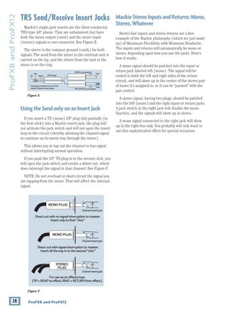
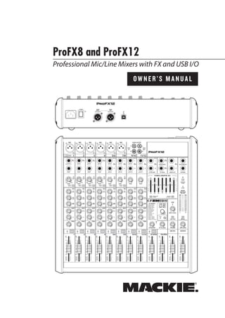
3-BAND EQ
The ProFX mixer has 3-band equalization at carefully
selected points — low shelving at 80 Hz, mid peaking at
2.5 kHz, and high shelving at 12 kHz. “Shelving” means
that the circuitry boosts or cuts all frequencies past the
specified frequency. For example, rotating the low EQ
knob 15 dB to the right boosts bass starting at 80 Hz and
continuing down to the lowest note you never heard.
“Peaking” means that certain
frequencies form a “hill”
around the center
frequency — 2.5 kHz in the case of
the mid EQ.
The following graphs of frequency vs. signal level
show the approximate overall effect of EQ adjustment
on the frequency range.
22. HI EQ
This control gives you
up to 15 dB boost or cut
above 12 kHz, and it is flat
(no boost or cut) at the
detent. Use it to add sizzle
to cymbals, and an overall
sense of transparency, or
edge to keyboards,
vocals,
guitar and bacon
frying. Turn
it down a little to reduce
sibilance, or to hide tape hiss.
23. MID EQ
Short for “midrange,”
this knob provides 15 dB
of boost or cut, centered at
2.5 kHz, also flat at the
center detent. Midrange
EQ is
often thought of as
the most dynamic, because
the frequencies that define
any particular sound are almost always found in this
range. You can create many interesting and useful EQ
changes by turning this knob down as well as up.
24. LOW EQ
This control gives you up
to 15 dB boost or cut below
80 Hz. The circuit is flat at
the center detent position.
This frequency represents
the punch in bass drums,
bass guitar, fat synth
patches, and some really
serious male singers.
Used in conjunction with
the low cut [21] switch,
you can boost the low EQ
without injecting a ton of
subsonic debris into the
mix.
MODERATION DURING EQ
With EQ, things may be upset royally. We’ve
designed a lot of boost and cut into each equalizer
circuit, because we know everyone will occasionally
need that. But if the EQs are maxed on every
channel, the resulting mix is mush. Equalize subtly
and use the left sides of the knobs (cut), as well as
the right (boost). Very few platinum-record-album
engineers ever use more than about 3 dB of EQ. If
more than that is necessary, there’s usually a better
way to get it, such as placing a mic differently (or
using a different kind of mic entirely).
25. AUX MON
These knobs tap a portion of each channel's signal
to set up a nice monitor mix feeding stage monitors,
independent of the main mix. Adjust these controls on
each channel until the band is happy with the stage
monitor mix.
The aux mon feed from hybrid and stereo channels is
a mono sum of the left and right sides of these channels.
The controls are off when turned fully down, deliver
unity gain at the center detent, and can provide up to
15 dB of gain turned fully up.
The channel fader [30], pan [27] and mute [29] do
not affect the monitor output, but the other channel
controls will. (The aux mon is pre-fader.)
The monitor signal from the monitor output jack [12]
is the sum (mix) of all the channels whose aux mon
control is set to more than minimum. The overall
output level may be adjusted with the monitor fader
[46] and its EQ tweaked with the graphic EQ [36]
if the main mix/mon switch [37] is pressed in.
Internal FX may also be added to the monitor mix
with the FX to mon knob [53].
20Hz 100Hz 1kHz 10kHz 20kHz
–15
–10
–5
0
+5
+10
+15
Mid EQ
20Hz 100Hz 1kHz 10kHz 20kHz
–15
–10
–5
0
+5
+10
+15
20Hz 100Hz 1kHz 10kHz 20kHz
–15
–10
–5
0
+5
+10
+15
Low EQ with Low Cut
Low EQ
20Hz 100Hz 1kHz 10kHz 20kHz
–15
–10
–5
0
+5
+10
+15
Hi EQ](https://image.slidesharecdn.com/profx812om-230216122837-d5649219/85/ProFX8_12_OM-pdf-19-320.jpg)
![20 ProFX8 and ProFX12
ProFX8
and
ProFX12
26. AUX FX
These knobs tap a portion of each channel's signal to
set up a nice FX mix feeding the internal FX processor,
and to feed external processors via the FX output [13].
The aux FX feed from hybrid and stereo channels is a
mono sum of the left and right sides of these channels.
The controls are off when turned fully down, deliver
unity gain at the center detent, and can provide up to
15 dB of gain turned fully up.
The channel fader [30], mute [29] and other channel
controls affect the FX output, but pan [27] does not.
(The aux FX is post-fader.)
The FX signal reaching the internal FX processor
and the FX send output jack, is the sum (mix) of all
the channels whose aux FX control is set to more than
minimum. The overall FX send level may be adjusted
with the FX master knob [51].
The FX signal from the internal FX processor is added
to the main mix using the FX return fader [45], and may
be added to the monitors with the FX to mon knob [53].
27. PAN
These knobs adjust the amount of channel signal sent
to the left versus the right outputs. On mono channels
these controls act as pan pots. On
hybrid and stereo
channels, they work like the balance control on a home
stereo. They do not affect the aux mon or FX mixes.
28. OL LED
This LED will light if the channel signal is too high,
and this may cause distortion due to overloading.
The OL LED comes before the channel fader [30] in
the signal path, so the fader has no effect in your efforts
to turn off the OL LED.
Overloading may occur if the gain [19] is set too high,
so check that the level set LED [20] is not turning on
frequently. Turn down the gain if it is.
Overloading may also occur if the channel EQ [22-24]
is set too high. Check that the EQ settings are moderate.
Use the low cut switches [21] if the overloading is due
to lower unwanted bass thumps and bangs.
29. MUTE
Press this switch in to mute the channel in the main
mix. The aux mon output of the channel is not muted,
but the FX output to the internal FX processor and FX
send jack [13] is.
30. CHANNEL FADER
These faders control the channel’s level from off, to
unity gain, on up to 10 dB of additional gain. The mono
channels have mono faders, and the hybrid and stereo
channels use stereo faders.
With the gain control [19] set correctly, the faders
should be set around unity gain (U).
8K
4K
2K
1K
500
250
125
15
15
10
10
5
5
0
15
15
10
10
5
5
0
ST RETURN MAIN OUT PHONES
FOOTSWITCH
PHONES
STEREO GRAPHIC EQ
FX SEND
MID
2.5kHz
MID
2.5kHz
MID
2.5kHz
MID
2.5kHz
MID
2.5kHz
80Hz
LOW
U
+15
-15
U
+15
-15
U
+15
-15
LINE IN 4
INSERT
R
L
LOW CUT
100 Hz
U
GAIN
M
IC GAIN
U +50
-20dB +30dB
4
12kHz
HI
MID
2.5kHz
80Hz
LOW
U
+15
-15
U
+15
-15
U
+15
-15
12kHz
HI
MID
2.5kHz
80Hz
LOW
U
+15
-15
U
+15
-15
U
+15
-15
12kHz
HI
MID
2.5kHz
80Hz
LOW
U
+15
-15
U
+15
-15
U
+15
-15
12kHz
HI
PAN
AUX
U
+15
O
O
MON
FX
U
+15
O
O
R
L
PAN
AUX
U
+15
O
O
MON
FX
U
+15
O
O
R
L
PAN
AUX
U
+15
O
O
MON
FX
U
+15
O
O
R
L
PAN
AUX
U
+15
O
O
MON
FX
U
+15
O
O
80Hz
LOW
U
+15
-15
U
+15
-15
U
+15
-15
R
L
LOW CUT
100 Hz
12kHz
HI
PAN
AUX
U
+15
O
O
MON
FX
U
+15
O
O
80Hz
LOW
U
+15
-15
U
+15
-15
U
+15
-15
LINE IN 7
LINE IN 8
UNBAL LINE IN 9
R
L
LOW CUT
100 Hz
GAIN
7/8
5/6
12kHz
HI
PAN
AUX
U
+15
O
O
MON
FX
U
+15
O
O
80Hz
LOW
U
+15
-15
U
+15
-15
U
+15
-15
R
L
MIC GAIN
U +50
GAIN
MIC GAIN
U +50
9/10
12kHz
HI
LEVEL
SET
LEVEL
SET
LEVEL
SET
LOW CUT
100 Hz
U
GAIN
M
IC GAIN
U +50
-20dB +30dB
LEVEL
SET
LEVEL
SET
LEVEL
SET
LOW CUT
100 Hz
U
GAIN
M
IC GAIN
U +50
-20dB +30dB
LOW CUT
100 Hz
U
GAIN
M
IC GAIN
U +50
-20dB +30dB
PAN
AUX
U
+15
O
O
MON
FX
U
+15
O
O
GAIN
80Hz
LOW
U
+15
-15
U
+15
-15
U
+15
-15
U
+20
-20
GAIN
U
+20
-20
R
L
11/12 ST RTN FX RTN
EQ
EQ
EQ
EQ EQ EQ EQ EQ
12kHz
HI
PAN
AUX
U
+15
O
O
MON
FX
U
+15
O
O
U
+15
FX TO MON
FX MASTER
U
+15
O
O O
O
dB
30
20
10
10
O
O
40
50
5
5
U
60
dB
30
20
10
10
O
O
40
50
5
5
U
60
dB
30
20
10
10
O
O
40
50
5
5
U
60
dB
30
20
10
10
O
O
40
50
5
5
U
60
dB
30
20
10
10
O
O
40
50
5
5
U
60
dB
30
20
10
10
O
O
40
50
5
5
U
60
dB
30
20
10
10
O
O
40
50
5
5
U
60
dB
30
20
10
10
O
O
40
50
5
5
U
60
dB
30
20
10
10
O
O
40
50
5
5
U
60
dB
30
20
10
10
O
O
40
50
5
5
U
60
dB
30
20
10
10
O
O
40
50
5
5
U
60
dB
30
20
10
10
O
O
40
50
5
5
U
60
R
LINE IN 5
LINE IN 6
UNBAL
R
LINE IN 10
UNBAL
R
LINE IN 11
LINE IN 12
UNBAL
R
UNBAL
R
UNBAL
R
MON SEND
BAL /
UNBAL
PRESETS
FX PRESETS
01 BRIGHT ROOM
02 WARM LOUNGE
03 SMALL STAGE
04 WARM THEATER
05 WARM HALL
06 CONCERT HALL
13 DELAY 1 (300ms)
14 DELAY 2 (380ms)
15 DELAY 3 (480ms)
16 REVERB + DLY (250ms)
07 PLATE REVERB
08 CATHEDRAL
09 CHORUS
10 CHORUS + REV
11 DOUBLER
12 TAPE SLAP
MON MAIN
LINE IN 3
INSERT
3
LINE IN 2
INSERT
2
LINE/HI-Z IN 1
INSERT
0dB=0dBu
MAIN
METERS
OL
4
6
3
10
15
7
10
20
30
0
2
BREAK
(MUTES ALL CHANNELS)
PHANTOM
POWER
POWER
O
O +10
U
TAPE LEVEL
O
O +20
U
USB THRU
O
O MAX
1
OL OL OL OL OL OL OL OL OL
OL
MAIN MIX
MON
EQ IN
BYPASS
R
L
INPUT LEVEL
USB
MUTE
MUTE MUTE MUTE MUTE MUTE MUTE MUTE MUTE MUTE
48V
19
20
21
22
23
24
25
26
27
28
29
30](https://image.slidesharecdn.com/profx812om-230216122837-d5649219/85/ProFX8_12_OM-pdf-20-320.jpg)
![21
Owner’s Manual
Owner’s
Manual
Master Controls
31. PHANTOM POWER SWITCH
If the microphones need phantom power, press
in this switch to add phantom power to all the XLR
microphone inputs of the mixer. This lets the mixer
send low-current DC voltage to the mic’s electronics
through the same wires that carry audio. The LED will
turn on as a reminder that phantom power is engaged.
Most modern professional condenser mics require
phantom power. Semi-pro condenser mics often have
batteries to accomplish the same thing. “Phantom” owes
its name to an ability to be “unseen” by dynamic mics
(Shure SM57/SM58, for instance), which don’t need
external power and aren’t affected by it anyway.
Never plug
single-ended (unbalanced)
micro
phones, or ribbon microphones into the
mic input jacks if phantom power is on. Do
not plug instrument outputs into the mic input jacks
with phantom power on,
unless you know for certain it
is safe to do so.
32. POWER LED
This LED comes on when the mixer is plugged into
the AC mains supply, and the rear panel power switch
[2] is on.
If the LED does not turn on, make sure the
AC power is live, both ends of the power cord are
correctly inserted, the electricity bill has been
paid and the lights in town are on.
33. METERS
These meters have 2 columns of 12 LEDs each,
with dB markings from –30 to +15, and OL (overload
at +20 dBu). They indicate the stereo signal strength
of the main mix after the main fader [47].
Typically, these meters should be bouncing between
the “0” and the “+3” LEDs. It is okay if the OL LEDs light
occasionally, but if they light frequently or continuously,
turn down the main fader until they blink occasionally
or not at all.
Remember, audio meters are just tools to help
assure
that the levels are “in the ballpark.” You don’t have to
stare at them (unless you want to).
8K
4K
2K
1K
500
250
125
15
15
10
10
5
5
0
15
15
10
10
5
5
0
ST RETURN MAIN OUT PHONES
PHONES
STEREO GRAPHIC EQ
FX SEND
MID
2.5kHz
GAIN
80Hz
LOW
U
+15
-15
U
+15
-15
U
+15
-15
U
+20
-20
R
L
11/12 ST RTN FX RTN
EQ
12kHz
HI
PAN
AUX
U
+15
O
O
MON
FX
U
+15
O
O
U
+15
FX TO MON
FX MASTER
U
+15
O
O O
O
dB
30
20
10
10
O
40
50
5
5
U
60
dB
30
20
10
10
O
O
40
50
5
5
U
60
dB
30
20
10
10
O
O
40
50
5
5
U
60
dB
30
20
10
10
O
O
40
50
5
5
U
60
dB
30
20
10
10
O
O
40
50
5
5
U
60
LINE IN 12
R R R
BAL /
UNBAL
PRESETS
FX PRESETS
01 BRIGHT ROOM
02 WARM LOUNGE
03 SMALL STAGE
04 WARM THEATER
05 WARM HALL
06 CONCERT HALL
13 DELAY 1 (300ms)
14 DELAY 2 (380ms)
15 DELAY 3 (480ms)
16 REVERB + DLY (250ms)
07 PLATE REVERB
08 CATHEDRAL
09 CHORUS
10 CHORUS + REV
11 DOUBLER
12 TAPE SLAP
MON MAIN
0dB=0dBu
MAIN
METERS
OL
4
6
3
10
15
7
10
20
30
0
2
BREAK
(MUTES ALL CHANNELS)
PHANTOM
POWER
POWER
O
O +10
U
TAPE LEVEL
O
O +20
U
USB THRU
O
O MAX
OL OL
OL
MAIN MIX
MON
EQ IN
BYPASS
R
L
INPUT LEVEL
USB
MUTE
MUTE MUTE
48V
36
37 38
31
32
33
34
35
41
53
51
49
48
50
39
40
44 45 46 47
42 43
52](https://image.slidesharecdn.com/profx812om-230216122837-d5649219/85/ProFX8_12_OM-pdf-21-320.jpg)
![22 ProFX8 and ProFX12
ProFX8
and
ProFX12
34. BREAK SWITCH
This important “take-a-break” switch quickly mutes
all the microphones and line-level inputs when the band
is between sets. This will prevent protestors or rogue
karaoke singers from storming the stage at the interval.
The monitor send [12] and FX send [13] are not
affected. Check this switch first if you are having trouble
with no sound in the system.
You can still play the stereo RCA tape inputs [17] in
the main stereo mix, and play audio coming in from your
computer via the USB inputs. For example, you could
play a soothing CD while the band is off stage.
35. TAPE LEVEL
This knob controls the input level of signals entering
the tape inputs. It is conveniently located close to the
break switch [34] so all channels may be quickly muted
while bringing up the background music while the band
is taking a break.
36. STEREO GRAPHIC EQ
This 7-band graphic equalizer adjusts the main mix
output. It affects the line-level outputs [3, 14], but not
the tape outputs [18], headphones [16], or the USB
output [4]. This EQ may be used for the monitor mix
instead of the main mix, if the main mix/mon switch
[37] is engaged. It may also be quickly bypassed using
the EQ in/bypass switch [38].
Each slider adjusts the level of its frequency band,
with up to 15 dB of boost or cut, and no change in level
at the center (0 dB) position. The frequency bands are:
125, 250, 500, 1k, 2k, 4k, and 8kHz.
The EQ section comes before the main fader [47]
and meters [33]. As with the channel EQ, just take it
easy. There is a large amount of adjustment, and if you
are not careful, you can upset the delicate balance of
nature. Although it may not seem cool to actually turn
down controls, with EQ it is often your best option. Turn
down the offending frequency range, rather than boost
the wanted range. Use it to reduce the level of some
frequency bands where feedback occurs.
37. MAIN MIX/MON
Use this switch to choose if the stereo graphic
EQ [36] is used for the stereo left and right main
mix or if it is used for the monitors. For example,
there may be times when the graphic EQ may be
used wisely in the monitor mix to reduce feedback
in the monitors from nearby microphones.
38. EQ IN/BYPASS
Use this switch to quickly engage or disengage the
stereo graphic EQ. This may be used for quick checks
of EQ settings or to shorten the signal path if not using
the EQ.
39. USB INPUT LEVEL
This control adjusts the signal level of the two chan-
nels coming in from the computer, via the USB port,
relative to the mix of the other channels. Adjust it care-
fully to achieve the desired mix with the other channels.
The USB input from audio software such as Tracktion,
could be individual instrument tracks, a mix of tracks,
or processed tracks.
8K
4K
2K
1K
500
250
125
15
15
10
10
5
5
0
15
15
10
10
5
5
0
ST RETURN MAIN OUT PHONES
PHONES
STEREO GRAPHIC EQ
FX SEND
MID
2.5kHz
GAIN
80Hz
LOW
U
+15
-15
U
+15
-15
U
+15
-15
U
+20
-20
R
L
11/12 ST RTN FX RTN
EQ
12kHz
HI
PAN
AUX
U
+15
O
O
MON
FX
U
+15
O
O
U
+15
FX TO MON
FX MASTER
U
+15
O
O O
O
dB
30
20
10
10
O
O
40
50
5
5
U
60
dB
30
20
10
10
O
O
40
50
5
5
U
60
dB
30
20
10
10
O
O
40
50
5
5
U
60
dB
30
20
10
10
O
O
40
50
5
5
U
60
dB
30
20
10
10
O
O
40
50
5
5
U
60
LINE IN 12
R R R
BAL /
UNBAL
PRESETS
FX PRESETS
01 BRIGHT ROOM
02 WARM LOUNGE
03 SMALL STAGE
04 WARM THEATER
05 WARM HALL
06 CONCERT HALL
13 DELAY 1 (300ms)
14 DELAY 2 (380ms)
15 DELAY 3 (480ms)
16 REVERB + DLY (250ms)
07 PLATE REVERB
08 CATHEDRAL
09 CHORUS
10 CHORUS + REV
11 DOUBLER
12 TAPE SLAP
MON MAIN
0dB=0dBu
MAIN
METERS
OL
4
6
3
10
15
7
10
20
30
0
2
BREAK
(MUTES ALL CHANNELS)
PHANTOM
POWER
POWER
O
O +10
U
TAPE LEVEL
O
O +20
U
USB THRU
O
O MAX
OL OL
OL
MAIN MIX
MON
EQ IN
BYPASS
R
L
INPUT LEVEL
USB
MUTE
MUTE MUTE
48V
36
37 38
31
32
33
34
35
41
53
51
49
48
50
39
40
44 45 46 47
42 43
52](https://image.slidesharecdn.com/profx812om-230216122837-d5649219/85/ProFX8_12_OM-pdf-22-320.jpg)
![23
Owner’s Manual
Owner’s
Manual
40. USB THRU
In addition to a mix of the other channels, the USB
output to the computer may contain any input from
the computer if this switch is down. (This switch only
affects the output to the computer, not the headphones
or main mix.)
• If disengaged (out), the USB output to the
computer will just be the main mix. This is a
good position for overdubbing, as any playback
from the computer may be played through the
main speakers and headphones, while playing
along with a guitar and recording only the
guitar via USB. This is also good for live
recording as a safeguard against feedback.
Here, the USB level knob should also be down.
• If pressed in, the USB output to the computer
will be the main mix, including any audio
coming in from the computer. This is a good
position to record live performances where
playback of audio from the computer is also
part of the performance.
41. PHONES LEVEL
This controls the volume of the headphones output
from off to maximum gain.
Warning: The headphone amplifier is
designed to drive any standard headphones
to a very loud level. It can cause permanent
hearing damage. Even intermediate levels may be
painfully loud with some headphones. Be careful!
Always start with the phones level control turned all
the way down before connecting headphones or making
any connections. Keep it down until you’ve put on the
headphones, and turn it down first whenever you play a
new source or instrument.
42. OL LED (for stereo returns)
This LED will light if the signal coming into the
stereo return inputs [11] is too high, and this may
cause distortion due to overloading.
The OL LED comes before the stereo return fader
[44], so the fader has no effect in your efforts to turn
off the OL LED.
Check external processors and other devices, and
turn down their levels until the OL LED does not come
on.
43. MUTE (for stereo returns)
Press this switch in to mute the signals coming into
the stereo return inputs [11].
44. STEREO RETURN FADER
Use this fader to lovingly adjust the level of any audio
coming into the stereo return inputs [11] from external
processors or other equipment. The audio is added to
the main mix and it may also be muted with the stereo
return mute switch [43].
Typically, this fader can just live at the unity “U” mark,
and the external device’s output control set at whatever
they call unity gain (check the manual of the effects
unit, CD player, drum machine, or whatever). If that
turns out to be too loud or too quiet, adjust the external
device’s outputs, not the mixer. That way, the mixer’s
faders are easy to relocate at the unity “U” mark. The
range is off to +10 dB.
45. FX RETURN FADER
Use this fader to gently adjust the level of the stereo
output from the internal FX processor being added to
the main mix. The range is off to +10 dB with unity at
“U”.
46. MONITOR FADER
This fader controls the overall level of
the monitor
send signal sent out to the stage monitors.
Adjust it carefully and check that the band is happy
with the levels. The fader does not affect the main mix
level.
The monitor send signals are off with the fader
fully down, the “U” marking is unity gain, and fully
up provides 10 dB of additional gain.
47. MAIN FADER
This fader controls the level of
the main mix and
affects the meters [33] and main line-level outputs
[3, 14]. The level adjustment occurs after the stereo
graphic EQ [36] in the signal path.
This gives you ultimate control over the audience.
Adjust it carefully, with a good eye on the meters to
check against overloading and a good ear on the levels
to make sure the audience is happy.
The control does not affect the monitor send [12],
tape output [18], headphones [16], or USB output [4].
The main mix signals are off with the fader fully down,
the “U” marking is unity gain and fully up provides
10 dB of additional gain. This additional gain will
typically never be needed, but once again, it’s nice to
know it’s there. The level control is stereo, as it affects
both the left and right of the main mix equally. This is
the control to turn down at the end of the song when
you want “The Great Fade-Out.”](https://image.slidesharecdn.com/profx812om-230216122837-d5649219/85/ProFX8_12_OM-pdf-23-320.jpg)
![24 ProFX8 and ProFX12
ProFX8
and
ProFX12
Stereo Effects Processor
The Mackie Running-Man 32-bit internal effects
processor is a mono-in, stereo-out effects processor,
with 16 presets. It is fed by adjusting the aux FX control
[26] on each channel. The FX master knob [51] adjusts
the overall level entering the FX processor and the
OL LED [52] shows if the level is too high.
The output from the processor may be added to
the main mix by adjusting the FX return fader [45].
Its output may also be added to the monitor mix by
adjusting the FX to mon knob [53].
48. PRESET DISPLAY
This display shows the number of the currently
selected effects preset, as shown in the list of presets
silkscreened to the left of the display.
49. PRESET SELECTOR
Rotate this knob to increase or decrease the number
of the preset. The available presets are shown in the
table on the next page and are marked on the panel
silkscreen. (Only one preset may be selected at a time.)
50. INTERNAL FX MUTE and LED
When engaged, the internal effects processor is
muted. Its output will not appear in the main mix or
monitors, and the adjacent LED will come on. The
footswitch connection [15] becomes disabled and the
footswitch cannot be used to mute or un-mute the
effects.
If this switch is not engaged, then the internal effects
may be muted or un-muted with a footswitch.
51. FX MASTER
Use this knob to control the level of
the signals going
into the internal effects processor. Adjust it carefully,
with an inner magical eye on the adjacent OL LED [52]
to prevent overloading the effects processor.
Fully down is off, 12 o'clock is unity gain, and fully up
is 15 dB of gain.
It also affects the level going out of the FX send
output [13].
52. OL LED
This LED illuminates when the effects processor is
being overloaded with too strong a signal (OL). Turn
down the FX master [51] if it is.
The signals going into the processor are affected by
the channel aux FX controls [26], and the channel
faders [30]. Check the LED if these controls have been
altered.
53. FX TO MON
This knob adds the output of the internal FX
processor to the stage monitor mix. Fully down is off,
12 o'clock is unity gain, and fully up is 15 dB of gain.
8K
4K
2K
1K
500
250
125
15
15
10
10
5
5
0
15
15
10
10
5
5
0
ST RETURN MAIN OUT PHONES
PHONES
STEREO GRAPHIC EQ
FX SEND
MID
2.5kHz
GAIN
80Hz
LOW
U
+15
-15
U
+15
-15
U
+15
-15
U
+20
-20
R
L
11/12 ST RTN FX RTN
EQ
12kHz
HI
PAN
AUX
U
+15
O
O
MON
FX
U
+15
O
O
U
+15
FX TO MON
FX MASTER
U
+15
O
O O
O
dB
30
20
10
10
O
O
40
50
5
5
U
60
dB
30
20
10
10
O
O
40
50
5
5
U
60
dB
30
20
10
10
O
O
40
50
5
5
U
60
dB
30
20
10
10
O
O
40
50
5
5
U
60
dB
30
20
10
10
O
O
40
50
5
5
U
60
LINE IN 12
R R R
UNBAL
PRESETS
FX PRESETS
01 BRIGHT ROOM
02 WARM LOUNGE
03 SMALL STAGE
04 WARM THEATER
05 WARM HALL
06 CONCERT HALL
13 DELAY 1 (300ms)
14 DELAY 2 (380ms)
15 DELAY 3 (480ms)
16 REVERB + DLY (250ms)
07 PLATE REVERB
08 CATHEDRAL
09 CHORUS
10 CHORUS + REV
11 DOUBLER
12 TAPE SLAP
MON MAIN
0dB=0dBu
MAIN
METERS
OL
4
6
3
10
15
7
10
20
30
0
2
BREAK
(MUTES ALL CHANNELS)
PHANTOM
POWER
POWER
O
O +10
U
TAPE LEVEL
O
O +20
U
USB THRU
O
O MAX
OL OL
OL
MAIN MIX
MON
EQ IN
BYPASS
R
L
INPUT LEVEL
USB
MUTE
MUTE MUTE
48V
53
51
49
48
50
52](https://image.slidesharecdn.com/profx812om-230216122837-d5649219/85/ProFX8_12_OM-pdf-24-320.jpg)