This document provides an owner's manual and precautions for a product. It contains 3 sections - FCC information noting the product meets FCC requirements when installed as indicated, important safety information warning of fire and electric shock hazards if not installed properly, and precautions for correct and safe operation of the product.


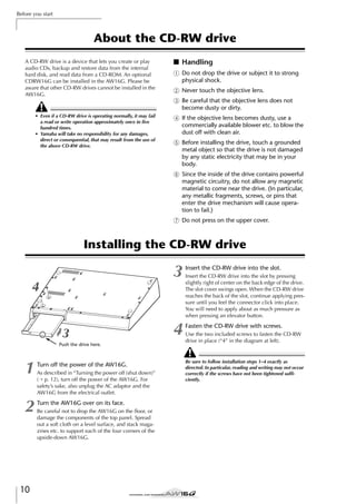
![Before you start
Connecting the AC adaptor
When connecting the included AC adaptor (PA-300), you
must first connect it to the DC IN jack of the AW16G,
and then to the AC wall outlet. After connecting the AC
adaptor to the AW16G, wrap the cable around the hook
as shown in the diagram. This will prevent the cable from
being accidentally pulled out, causing the AW16G to
unexpectedly lose power.
DC IN
Turning the power on/off
1
In the work navigate section located in the
upper left of the top panel, press the [SONG]
key several times to access the following
SHUTDOWN page.
2
Press the [ENTER] key located in the middle
right of the top panel.
3
Using the CURSOR [ ]/[ ] keys located in
the upper right of the top panel, move the
cursor (the blinking area in the screen) to the
YES button if you want to save the current
song, or to the NO button if you do not want
to save it. Then press the [ENTER] key.
4
You must use the following procedure to switch the
power of the AW16G between ON and STANDBY. If you
fail to follow this procedure, the internal hard disk or
your external monitor system may be damaged.
When the “Now safe to turn off...” message
appears, turn off the [POWER] switch located
on the rear panel.
■ Turning the power on
In a system that includes the AW16G, turn the power of
each device on in the following order.
1 External devices such as audio sources and
effect processors connected to the input/output jacks of the AW16G
B The AW16G itself
C The monitor system connected to the
AW16G’s output jacks
Before you turn on the power, make sure that the AC
adaptor is firmly connected to the AW16G and to the AC
outlet. If the power is disconnected while the AW16G is
being used, the AW16G itself or the hard disk may be
damaged.
When you turn on the power of the AW16G, an opening
screen will appear, and then the following screen will
appear.
A popup window will ask you whether you want to
save the current song.
■ Turning the power off (shut down)
In a system that includes the AW16G, turn the power of
each device off in the following order.
1 The monitor system connected to the
AW16G’s output jacks
B The AW16G itself
C External devices such as audio sources and
effect processors connected to the input/output jacks of the AW16G
When turning off the power of the AW16G, you must
perform the following “shut-down” procedure.
12
If you turn off the power of the AW16G without performing the above shutdown procedure, not only will any
unsaved changes be lost, but you also risk damaging the
data on the hard disk, and damaging or drastically shortening the lifespan of the hard disk itself and the internal
CD-RW drive. Please use caution.
Tip!
A small amount of electrical current is flowing even when
the power is in STANDBY mode. If you will not be using
the AW16G for an extended period of time, be sure to
disconnect the AC adaptor from your AC outlet.](https://image.slidesharecdn.com/aw16ge-131126034127-phpapp02/85/Aw16-ge-12-320.jpg)


![Introducing the AW16G
■ Input/output section
3
1
2
1 [GAIN] knobs 1–8
C [MONITOR/PHONES] knob
These adjust the sensitivity of the signals that are
input from the rear panel MIC/LINE INPUT jacks 1–8.
B [INPUT SEL] keys 1–8
This knob adjusts the level of the signal that is output from the MONITOR OUT jacks and the
PHONES jack.
These keys select the mixer input channel that you
will operate.
■ Work Navigate section
B [MONITOR] key
1
2
3
4
5
This key accesses the MONITOR screen, where you
can quickly select the signal to be monitored, or
switch the stereo track playback on/off.
6
■ Display
1
2
1 [SONG] key
This key accesses the SONG screen, where you can
save or load songs, and perform the shut-down procedure.
B [CD] key
This key accesses the CD screen, where you can
write or play an audio CD, and backup or restore
data.
C [TRACK] key
This key accesses the TRACK screen, where you can
check whether each track contains data, and switch
the virtual tracks that will be used for recording and
playback.
D [EDIT] key
This key accesses the EDIT screen, where you can
copy or erase tracks.
This is a backlit liquid crystal display that indicates the
current operating status or the settings of the various
parameters. The screens that are displayed will depend
on the front panel keys and knobs that are operated.
1 Access indicator
This indicator indicates the access status of the
internal hard disk. When the hard disk is being read
or written, this indicator will light.
Never turn off the power of the AW16G when the access
indicator is lit. Doing so will not only damage the data on
the internal hard disk, but may also damage the hard disk
itself. When you want to turn off the power of the AW16G,
you must perform the shutdown procedure (→ p. 12).
B Contrast
Adjusts the brightness of the display.
E [REMOTE] key
This key accesses the REMOTE screen, where you
can use the front panel faders and [TRACK SEL]
keys to control an external MIDI device or
sequencer software on your computer.
■ Quick Loop Sampler section
F [UTILITY] key
This key accesses the UTILITY screen, where you
can make MIDI, oscillator, and digital input settings, and format the hard disk.
2
3
1 [PAD SEL] key
■ Quick Navigate section
1
1
Hold down this key and press a pad 1–4 to select a
pad for operations.
2
B Pads 1–4
Each of these pads plays back the sample that has
been assigned to it.
1 [RECORD] key
This key accesses the RECORD screen, where you
can quickly assign the signal to be recorded to the
input of each track, and make settings for recording.
18
C [SAMPLE EDIT] key
This key accesses the SAMPLE screen, where you
can make settings and perform operations for the
quick loop sampler.](https://image.slidesharecdn.com/aw16ge-131126034127-phpapp02/85/Aw16-ge-18-320.jpg)
![■ Mixer section
2
1
3
2
Introducing the AW16G
4
5
1 [TRACK SEL] keys 1–8
B [TRACK SEL] keys 9/10–15/16
C [STEREO SEL] key
6
D Faders 1–8
E Faders 9/10–15/16
Normally, these faders adjust the playback level of
each recorder track. By changing the internal settings, you can also use these faders to control the
input levels of input channels 1–8 and pads 1–4.
Use these keys to select the mixer track channels or
recorder tracks that you want to control.
F [STEREO] fader
This adjusts the output level of the stereo bus.
■ Selected Channel section
1
6
2
7
3
8
4
9
5
C [EFF 1] knob
D [EFF 2] knob
J
Turning these knobs will adjust the amount of signal
that is sent from the currently selected channel to
the internal effects 1 and 2 (i.e., effect send levels 1
and 2). You can press these knobs to access the
EFF1 or EFF2 screens, where you can adjust the
parameters of the internal effects.
E [PAN/BAL] knob
Turning this knob will adjust the pan of the currently selected channel (or the balance of the stereo
output channel). You can press this knob to access
the PAN screen, where you can adjust pan for multiple channels.
1 [EQ] knob
Turning this knob will adjust the EQ (equalizer) gain
for the currently selected channel. You can press
this knob to access the EQ screen, where you can
adjust all of the EQ settings.
B [DYN] knob
Turning this knob will adjust the dynamics depth for
the currently selected channel. You can press this
knob to access the DYN screen, where you can
adjust all of the dynamics settings.
F
G
H
I
[HIGH] key
[HI-MID] key
[LO-MID] key
[LOW] key
These keys select one of the four EQ bands (HIGH,
HI-MID, LO-MID, LOW) to be adjusted.
J [VIEW] key
This key accesses the VIEW screen, where you can
check the level of each channel, or perform onscreen adjustments to the faders and other mix
parameters of each channel.
19](https://image.slidesharecdn.com/aw16ge-131126034127-phpapp02/85/Aw16-ge-19-320.jpg)
![Introducing the AW16G
■ Data entry/control section
■ Locate section
4
1
4
7
8
3
3
1
2
2
9
5
5
6
6
1 [SOUND CLIP] key
This key accesses the CLIP screen, where you can
record or play sound clips.
1 [UNDO/REDO] key
This key cancels the results of a recording or track
editing operation (Undo), or re-executes a cancelled operation (Redo).
B [AUTO PUNCH] key
Tip!
C [REPEAT] key
• This key will light if Undo can be performed.
• If you press and hold this key, the UNDO LIST screen
will appear. Here you can turn the [DATA/JOG] dial to
revert as many as the last fifteen operations (→ p. 61).
B [SCENE] key
This key accesses the SCENE screen, where you can
save or recall scene memories.
C [JOG ON] key
This key is an on/off switch for the Nudge function
(→ p. 71) which uses the [DATA/JOG] dial (5).
When this function is on, the key will light.
D [CURSOR] keys ([
]/[
]/[
]/[
] keys)
These keys move the cursor in the screen (the blinking frame) to select a specific item.
E [DATA/JOG] dial
Use this dial to change the value of a parameter. If
the [JOG ON] key (3) is on, this dial operates the
Nudge function.
F [ENTER] key
Use this key to operate a button displayed in the
screen, or to execute a specific function.
This key switches the audio punch-in/out function
on/off, letting you automate recording.
This key switches the A-B repeat function on/off, letting you repeatedly play a specified region.
D MARK SEARCH [
]/[
] keys
These keys search for markers placed within the
song.
E [IN]/[OUT] keys
These keys specify the points at which auto punchin/out recording will begin (the In point) and end
(the Out point). These keys can also be used as
locate keys to move directly to the In point or Out
point.
F [A]/[B] keys
These keys specify the points at which the Repeat
function will begin (point A) and end (point B).
These keys can also be used as locate keys to move
directly to point A or point B.
G [MARK] key
This key places a mark at the current location of the
song.
H [SET] key
Use this key in conjunction with the [IN]/[OUT]
keys or the [A]/[B] keys to register the current location as a locater.
I [CANCEL] key
Use this key in conjunction with the [IN]/[OUT]
keys or the [A]/[B] keys to cancel a locater that you
registered.
20](https://image.slidesharecdn.com/aw16ge-131126034127-phpapp02/85/Aw16-ge-20-320.jpg)
![■ Transport section
1
C FF [
2
] key
This key fast-forwards the current location. Each
time you press this key, you will alternate between
8x speed and 16x speed.
3
D STOP [■] key
E PLAY [
4
1 RTZ [
5
6
] key
This key moves directly to the relative zero time
location. Used in conjunction with the [SET] key,
this registers the current location as the relative zero
time.
F REC [●] key
If you hold down this key and press the PLAY [ ]
key while the recorder is stopped, recording will
begin.
If you hold down this key and press the PLAY [ ]
key during playback, you will switch from playback
to recording (“punch-in”).
Tip!
Broadly speaking, the times displayed in the AW16G’s
counter can be either absolute time (ABS) or relative
time (REL). The absolute time zero location is fixed, but
the relative time zero location can be freely specified.
B REW [
] key
If you press this key while the recorder is stopped,
playback will begin.
If you press this key during fast-forward or rewind,
normal-speed playback will begin.
If you press this key during recording, recording
will stop and playback will resume (“punch-out”).
] key
This key rewinds the current location. Each time
you press this key, you will alternate between 8x
speed and 16x speed.
Rear panel
6
N
5
M L
4
K
1 MIC/LINE INPUT (XLR) jacks 1/2
These are XLR-3-31 type balanced input jacks. The
nominal input level is –46 to +4 dB. Mics, direct
boxes, or line level devices with balanced output
jacks can be connected here. The pin configuration
is shown below.
Male XLR connector
1 (ground)
3 (cold)
2 (hot)
B MIC/LINE INPUT (TRS phone) jacks 3–8
These are TRS phone type 1/4" input jacks (balanced). The nominal input level is –46 to +4 dB.
Devices such as synthesizers or rhythm machines
with unbalanced outputs can also be connected
here. The pin configuration is shown below.
1/4" TRS phone plug
Ring (cold)
Tip (hot)
3
J
2
9
8
1
7
C MIC/LINE INPUT jack 8 (Hi-Z)
This is a high impedance 1/4" phone input jack
(unbalanced). The nominal input level is –46 to +4
dB. An instrument with high output impedance
such as an electric guitar or bass with passive-type
pickups can be connected here.
D STEREO/AUX OUT jacks
These are 1/4" phone output jacks (unbalanced) that
output the signals of the stereo bus or AUX bus 1/2.
E MONITOR OUT jacks
These are 1/4" phone output jacks (unbalanced) for
connection to your monitor setup, such as a stereo
system or powered speakers.
F PHONES jack
This is a 1/4" TRS phone output jack for connecting
your headphones for monitoring.
Sleeve (ground)
21
2
Introducing the AW16G
This key stops playback, recording, fast-forward, or
rewind.](https://image.slidesharecdn.com/aw16ge-131126034127-phpapp02/85/Aw16-ge-21-320.jpg)

![Basic operation on the AW16G
The display of the AW16G shows the following information.
2
3
4
● Knob/fader/parameter display area
The knob/fader/parameter display area within the
display is used to edit the value of the corresponding parameter.
5
Knob
1 Screen name
fader
parameter display
area
● Page display area
Most screens are divided by function into two or more “pages.” The
page display area lists the pages
that can be selected within that
screen. The name of the currently
selected page is highlighted.
This is the name of the currently selected screen.
B Selected channel
This indicates the mixer channel that is selected for
operations. The display has the following significance.
TRACK 1–8 ...........................Track channels 1–8
TRACK 9/10–15/16...............Track channels 9/10–15/16
INPUT 1–8............................Input channels 1–8
STEREO.................................Stereo output channel
PAD 1–4................................Pad channels 1–4
Operating the knobs or keys of the Selected Channel section will edit the parameters of the channel
that is selected here.
C Counter (left side)
This indicates the current location within the song.
When the AW16G is in the default state, this
counter will indicate the absolute time (the time
from where you began recording the song) in units
of hours/minutes/seconds/milliseconds. At the left
of this value is displayed the locate point or marker
that was passed most recently.
D Counter (right side)
This indicates the current location within the song
in units of measures/beats. The measures/beats are
calculated according to the tempo and time signature specified in the tempo map for the song. The
current tempo and time signature are displayed at
the left of this value.
E Main screen
Accessing a screen/page/channel
When you want to edit an internal setting of the AW16G,
or to edit a parameter that cannot be operated by a fader
or knob shown in the display, you will need to access the
desired screen and page.
1
Press the key or knob for the desired screen.
The keys and knobs of various sections listed below
have their own screens, and the corresponding
screen will be displayed when you press a key or
knob.
• All keys in the Work Navigate section
• All keys in the Quick Navigate section
• The [VIEW] key of the Selected Channel section
• All knobs of the Selected Channel section
• The [SAMPLE EDIT] key of the Quick Loop Sampler section
Tip!
When you switch screens, the page that was last used in
that screen will be displayed.
The information displayed in this area will depend
on the key that was last pressed. The following types
of object are displayed in the main screen.
● Cursor
The blinking frame within the display is
called the “cursor.” When an object in the
screen is enclosed by the cursor, that
object is selected for operations.
23
Introducing the AW16G
Viewing the display
1
2
● Buttons
Buttons in the display are used to
switch a parameter on/off, to select
one of multiple choices, or to execute a specific function. A button
that is currently on will be displayed in black with white text. A
button that is currently off will be
displayed in white with black text.
This section explains basic operations on the AW16G.](https://image.slidesharecdn.com/aw16ge-131126034127-phpapp02/85/Aw16-ge-23-320.jpg)
![Introducing the AW16G
2
To switch pages within a screen, you can
either repeatedly press the same key as in
step 1, or hold down the same key as in step
1 and use the CURSOR [ ]/[ ] keys.
If there are more pages than can
be shown in one screen, an
arrow like the following will
appear in the page display area.
This arrow means that one or
more additional hidden pages
exist in that direction.
To access a hidden page, hold down the same key
as in step 1, and press the [CURSOR] key of the
same direction as the arrow.
In pages that display a list of parameters for multiple
channels, the screen may be divided into a page for
the input channels/pad channels and a page for the
track channels, since not all of the parameters can
be shown in a single screen. In this case, use the
[INPUT SEL] keys, pads 1–4, or [TRACK SEL] keys
to select the channels that you want to view.
Inputting text
When you create a new song or save a scene memory or
library setting, a popup window will appear, allowing
you to assign a name for the song or setting.
2
1
5
1
2
This box lets you input characters, numerals, and
symbols. When you save the data for the first time,
the box will contain a default name.
You can input a scene/library name or song name of
up to twelve characters.
24
B Text palette
This displays the characters, numerals, and symbols
that can be input in the text input box.
C CANCEL button
Press the [ENTER] key.
D OK button
The button will be switched on/
off.
If you move the cursor to a button that executes a specific
function and then press the
[ENTER] key, that function will
be executed.
E
Here’s how to edit the value of a fader, knob, or parameter shown in the display.
2
7
1 Text input box
Use the [CURSOR] keys to
move the cursor to the
desired button in the
screen.
Editing a value in the display
1
6
This popup window contains the following items and
functions.
Switching a button on/off
Here’s how to switch a button in the screen on/off.
3
4
Use the [CURSOR]
keys to move the cursor to the desired
fader, knob, or parameter value.
Turn the [DATA/JOG]
dial to edit the value.
If you move the cursor to this button and press the
[ENTER] key, you will return to the previous screen
without changing the name.
If you move the cursor to this button and press the
[ENTER] key, the scene/library will be saved or the
new song will be created.
button
If you move the cursor to this button and press the
[ENTER] key, the character that is currently selected
in the text input box will be switched between
uppercase and lowercase.
F INS button
When you move the cursor to this button and press
the [ENTER] key, a space will be inserted at the
location of the currently selected character (underlined), and subsequent characters will move one
character backward.
G DEL button
When you move the cursor to this button and press
the [ENTER] key, the currently selected character
(underlined) will be deleted, and subsequent characters will move one character forward.
To assign a new name, use the [CURSOR] keys to
move the cursor in the text input box to the character that you want to change, and turn the [DATA/
JOG] dial to select a character.
When you have finished inputting the name, move
the cursor to the OK button and press the [ENTER]
key to apply the new name.](https://image.slidesharecdn.com/aw16ge-131126034127-phpapp02/85/Aw16-ge-24-320.jpg)
![Using the Selected Channel section
Note
You can use the knobs and keys of the Selected Channel
section to directly operate the mix parameters (EQ,
dynamics, pan, etc.) of the currently selected channel.
1
Use the [TRACK SEL] keys, [INPUT SEL] keys,
[STEREO SEL] keys, or pads 1–4 to select the
channel that you want to operate.
When using the
Selected Channel
section, you must
first select the
channel that you
want to operate. The currently selected channel is
indicated in the upper left of the screen.
The channels correspond to each key or pad as follows.
[TRACK SEL] keys 1–8 ...........Track channels 1–8
[TRACK SEL] keys
9/10–15/16...........................Track channels 9/10–15/16
[INPUT SEL] keys 1–8 ...........Input channels 1–8
[STEREO SEL] key..................Stereo output channel
Pads 1–4................................Pad channels 1–4
2
According to the parameter you want to edit,
turn the five knobs of the Selected Channel
section.
3
If you want to access the screen for a parameter and edit it in greater detail, press one of
the five knobs or the [VIEW] button.
Pressing each knob or button will access the following screens.
Press the [EQ] knob
The EQ screen will appear.
Press the [DYN] knob
The DYN screen will appear.
Press the [EFF 1] knob
The EFF 1 screen will appear.
Press the [EFF 2] knob
The EFF 2 screen will appear.
Press the [PAN/BAL] knob
The PAN screen will appear.
Press the [VIEW] key
The VIEW screen will appear.
The following items will change when you turn
each knob.
● EQ screen EDIT page
Turn the [EQ] knob
This changes the amount of boost/cut for the selected
EQ band. To select the EQ band, use the [HIGH], [HIMID], [LO-MID], and [LOW] keys located at the right.
Turn the [DYN] knob
This changes the depth of dynamics processing.
Turn the [EFF 1] knob
This adjusts the level of the signal
that is sent from that channel to
internal effect 1. (If the stereo output
channel is selected, this adjusts the
return level from internal effect 1.)
Turn the [EFF 2] knob
This adjusts the level of the signal
that is sent from that channel to
internal effect 2. (If the stereo output
channel is selected, this adjusts the
return level from internal effect 2.)
4
Move the cursor in the screen to the desired
parameter, and use the [DATA/JOG] dial or
the [ENTER] key to operate the parameter.
Note
• If you change individual parameters in the DYN screen,
the parameter that you operate last will be assigned to
the [DYN] knob.
• If you want to return to the state in which turning the
[DYN] knob will adjust multiple parameters simultaneously, you must once again recall the library containing the dynamics settings you recalled prior to editing
in the DYN screen.
Turn the [PAN/BAL] knob
This adjusts the pan of the signal that is sent from that
channel to the stereo bus. (If the stereo output channel is selected, this adjusts the balance of the left and
right channels.)
25
2
Introducing the AW16G
• Simply turning the knobs of the Selected Channel section will not cause the screen to change.
• If you turn the [DYN] knob immediately after recalling
a preset library that includes dynamics settings, multiple dynamics parameters will change simultaneously,
affecting the way in which dynamics processing is
applied. The depth of this change will depend on the
library that is recalled.](https://image.slidesharecdn.com/aw16ge-131126034127-phpapp02/85/Aw16-ge-25-320.jpg)


![Listening to the demo song
Loading the demo song
Here’s how to load the demo song from the hard disk.
1
In the work navigate section, press the [SONG] key.
The SONG screen will appear,
where you can save or load
songs.
5
Move the cursor to either YES (save the current song) or NO (don’t save the current
song), and press the [ENTER] key.
The song data will be loaded, and “Ride with me”
will become the current song.
Note
If you select NO, any changes that you made to the current song since you last saved it will be lost.
2
Either press the [SONG] key repeatedly or
hold down the [SONG] key and use the CURSOR [ ]/[ ] keys to access the LIST page.
In this page, you can select a song on the hard disk,
and load or delete it.
2
1
1 List
This area lists the songs that are saved on the hard
disk. The line enclosed by the dotted frame in the
center of the list indicates the song that is selected
for operations. The highlighted line indicates the
song that is currently loaded into the AW16G. (This
is called the “current song.”)
B SORT field
These three buttons let you select how the songs in
the list will be sorted. Choose the NAME button
(sort alphabetically), OLD button (sort by save date),
or SIZE button (sort by size).
3
Turn the [DATA/JOG] dial to select the song
“Ride with me.”
4
Move the cursor to the LOAD
button in the screen, and press
the [ENTER] key.
A popup window like the following
will appear. This window asks you
whether you want to save the current
song.
28](https://image.slidesharecdn.com/aw16ge-131126034127-phpapp02/85/Aw16-ge-28-320.jpg)
![Playing the demo song
Here’s how to play back the demo song you loaded, and
adjust the monitor level.
1
4
Either press the [VIEW] key repeatedly or hold
down the [VIEW] key and use the CURSOR
[ ]/[ ] keys to access the VIEW screen
METER page.
To adjust the monitor level appropriately, use
the AW16G’s [MONITOR PHONES] knob and
the volume control of your monitor system.
Tip!
5
To stop the song, press the STOP [■] key.
The VIEW screen METER page contains meters that
show the input level of each channel and the output
level of the stereo output channel. It is convenient
to display this page when you want to check the
level of each track.
Note
Make sure that the selected channel area at the upper left
of the METER page indicates either TRACK 1–8 or TRACK
9/10–15/16. If neither of these are displayed, press either
the [TRACK SEL] key 1–8 or 9/10–15/16.
2
Lower the AW16G’s [STEREO] fader to the infinity position. Also make sure that the
AW16G’s [MONITOR PHONES] knob and the
volume of your monitor system are turned
down.
3
Press the PLAY [
] key.
The demo song will begin playing, and the level of
each track channel will be displayed in the METER
page of the VIEW screen.
29
3
Listening to the demo song
The demo song uses the Scene function to switch the settings of the mixer. This means that playback will occur
using the pre-specified balance — you do not need to
operate the faders.](https://image.slidesharecdn.com/aw16ge-131126034127-phpapp02/85/Aw16-ge-29-320.jpg)
![Listening to the demo song
Mixing the demo song
When you play back a song, tracks 1–16 of the recorder
are directly connected to track channels 1–8 and 9/10–
15/16 of the mixer. The signals that pass through track
channels 1–8 and 9/10–15/16 are sent to the stereo bus,
routed through the stereo output channel, and sent from
the STEREO/AUX OUT jacks or the MONITOR OUT
jacks.
● Signal flow during song playback
Recorder section
Track 1
Track 2
Track 3
Track 4
Track 5
Track 6
Track 7
Track 8
Track 9
Track 10
Track 11
Track 12
Track 13
Track 14
Track 15
Track 16
Track
channels
Stereo output
channel
Stereo bus
Mixer section
Track channels 1–8 and 9/10–15/16 are directly controlled by the faders and [TRACK SELECT] keys of the
panel. Here’s how you can adjust the mix level of each
track channel and switch it on/off while the song plays
back.
30](https://image.slidesharecdn.com/aw16ge-131126034127-phpapp02/85/Aw16-ge-30-320.jpg)
![1
Press the RTZ [
] key.
Note
The demo song will be rewound to the beginning.
4
The demo song will begin playing.
While listening to the demo song, try operating faders 1–8 and 9/10–15/16.
Notice that the level of the corresponding track will
change. Operating the [STEREO] fader will change
the overall level of the song.
6
7
To mute the playback of a
specific track, access the
MONITOR screen ON/
OFF page, either by
repeatedly pressing the
[MONITOR] key or by
holding down the [MONITOR] key and using
the CURSOR [ ]/[ ] keys.
The MONITOR screen ON/OFF page lets you
switch each channel on/off. A channel that is
switched off in this page will not be sent to the stereo bus or AUX bus, and will be muted.
5
In this page, pressing the [STEREO SEL] key will have no
effect.
] button.
To cancel the muted state, press the same
[TRACK SEL] key you pressed in step 5, to
make the indicator light green.
If you want to monitor the playback of just a
specific track, access the MONITOR screen
SOLO page by either repeatedly pressing the
[MONITOR] key or by holding down the
[MONITOR] key and using the CURSOR [ ]/
[ ] keys.
The SOLO page of the MONITOR screen lets you
mute all other channels while listening to only a
specific channel. (This is called the “solo” function.)
When you sol a channel in this page, the signals of
the remaining channels will be muted, and will no
longer be sent to the stereo bus or AUX buses.
8
Press the [TRACK SEL] key of the track channel that you want to solo.
Press the [TRACK SEL] key(s) for the track
channel(s) that you want to mute. (You may
select more than one channel.)
For example if you press [TRACK SEL] key 3, the
screen will change as follows, and channels other
than track channel 3 will be muted. At this time,
[TRACK SEL] key 3 will light orange, and the other
[TRACK SEL] keys and [INPUT SEL] keys will go
dark.
For example if you press [TRACK SEL] keys 1 and 3,
the screen will change as follows, and track channels 1 and 3 will be muted. At this time, [TRACK
SEL] keys 1 and 3 will go dark. The graphic in the
display will also indicate this.
Note
The [TRACK SEL] key you press last will always light
orange regardless of the mute status. This indicates that
this channel is the “selected channel” (→ p. 25).
Note
Only one channel can be soloed at a time.
9
To cancel soloing, press the currently
selected [TRACK SEL] key (lit orange) once
again.
Note
While playing the demo song, the level or the on/off status of a channel you adjusted manually may return to its
previous setting. This is because the Scene function has
switched the state of the mixer settings, and is not a malfunction (→ p. 142). You can use the Recall Safe function
to temporarily prevent scenes from being recalled. (→
p. 80)
31
3
Listening to the demo song
2
3
Press the PLAY [](https://image.slidesharecdn.com/aw16ge-131126034127-phpapp02/85/Aw16-ge-31-320.jpg)

![Recording to a sound clip
Adjusting the input level
The signals that are input from MIC/LINE INPUT jacks 1–
8 are sent to input channels 1–8 respectively. Here's how
to adjust the input level of the input channel, and make
settings so that you can hear the sound from your monitor system via the stereo bus.
1
Press and hold the [INPUT SEL] key for the
jack to which your instrument/mic is connected.
When you press and hold an [INPUT SEL] key, the
INPUT SETTING popup window will appear, allowing you to make settings for the corresponding input
channel. The following diagram is an example of
the screen that will appear if you press and hold
[INPUT SEL] key 1.
While you watch the level meter in the
popup window, produce sound on your
instrument, and turn the [GAIN] knob to
adjust the input level.
As you turn the [GAIN] knob toward the right, the
level meter in the popup window will move more
widely. (However, you will not yet hear anything
from your monitor system.)
For the best audio quality, adjust the level as high as
possible without allowing the meter to clip when
the loudest volume occurs.
Lower the [STEREO] fader to the –∞ position.
Also turn down the [GAIN] knob for the MIC/
LINE INPUT jack to which your instrument/
mic is connected.
2
3
4
While you play your
instrument, raise the
[STEREO] fader to the
0 dB position.
The LR meters at the right
of the screen will now
move. As you turn the
[MONITOR/PHONES] knob toward the right, you
should begin to hear sound from your monitor system.
2
Note
4
1
3
1 INPUT LEVEL knob
Move the cursor to this knob and turn the [DATA/
JOG] dial to adjust the level of the input channel.
Normally you will leave this at the default setting of
0 dB. The current level is shown by the value (dB
units) above the knob.
B Stereo bus assign switch
When you move the cursor to this knob and press
the [ENTER] key, the signal that is sent from the corresponding input channel to the stereo bus will be
switched on/off.
C Level meter
This indicates the input level of the input channel.
The
symbol in the window indicates the location at which the level is detected.
D EXIT button
Move the cursor to this button and press the
[ENTER] key to close the popup window and return
to the previous screen.
34
If you still do not hear sound after raising the [STEREO]
fader, check the INPUT SETTING popup window to make
sure that the stereo bus assign switch is turned on, and
that the INPUT LEVEL knob value has not been set below
0.0 dB.
5
To exit the INPUT SETTING popup window,
move the cursor to the EXIT button and press
the [ENTER] key.
You will return to the previous screen.
Tip!
The level settings described above are the basic settings
for any type of recording --- not just for a sound clip. By
using the [GAIN] knob to raise the level as far as possible
without allowing distortion to occur, you can ensure that
the input signal is converted into digital form with the
highest possible quality before it is input to the mixer section. If the [GAIN] knob is not raised sufficiently, you
may not be taking full advantage of the available dynamic
range of the mixer section and recorder section. When
the input LEVEL knob and [STEREO] fader are set to the
0 dB position, the input level will be output without
change to the recorder and monitor.](https://image.slidesharecdn.com/aw16ge-131126034127-phpapp02/85/Aw16-ge-34-320.jpg)
![Recording to a sound clip
■ Recording a sound clip
1
In the Locate section, press the [SOUND
CLIP] key.
5
Tip!
The CLIP screen will appear, where you can record
and play sound clips.
1
2
3 4
• The metronome sound will not be recorded in the
sound clip. If necessary, you can move the cursor to the
metronome knob and turn the [DATA/JOG] dial to
adjust the volume level of the metronome sound.
• In addition to an instrument connected to the MIC/
LINE INPUT jacks, your performance on the quick loop
sampler pads can also be recorded.
• The knobs/keys of the selected channel are active even
while the CLIP screen is displayed. If necessary, you can
record the signal processed by EQ and dynamics (→
p. 50).
5
1 Metronome button
Switches the metronome on/off.
B Metronome knob
Play your instrument in time with the metronome.
6
To stop recording, press the STOP [■] key.
The display will show S and E symbols to indicate
the start point and end point.
Adjusts the volume level of the metronome. The
value shown above the knob shows the current setting in dB units.
C START button
Specifies the current location as the start point of
the sound clip (the location at which playback will
begin). The current location is shown in minutes/
seconds/milliseconds at the left.
D END button
Specifies the current location as the end point of the
sound clip (the location at which playback will
end). The current location is shown in minutes/seconds/milliseconds at the left.
E CLIP button
When you turn this button on, the START button
(3) and END button (4) settings will be enabled.
Note
Recording and playback in the Recorder section cannot
be performed while the CLIP screen is displayed.
2
If you want to use the metronome, move the
cursor to the metronome button and press
the [ENTER] key.
The time signature and tempo used by the metronome are displayed above the metronome button.
3
To change the tempo of the metronome,
move the cursor to the tempo value and turn
the [DATA/JOG] dial.
Note
The time signature of the metronome is determined by
the tempo map setting immediately prior to accessing the
CLIP screen. Please be aware that the setting cannot be
edited from this screen. (For details on tempo map settings → p. 142)
4
36
In the Transport section, hold down the REC
[●] key and press the PLAY [ ] key.
The metronome will begin sounding, and the
counter display will advance. The counter in the
CLIP screen always starts from 0, and indicates the
current time in minutes/seconds/milliseconds. This
counter is separate from the counter of a conventional song.
Tip!
• With the default settings of the AW16G, a maximum of
30 seconds can be recorded in a sound clip. If you continue recording for longer than 30 seconds, the last 30
seconds of your playing before you stopped recording
will be recorded. (However, the counter display during
recording will continue to advance.)
• In the UTILITY screen PREFER page, you can specify up
to 180 seconds as the maximum length that can be
recorded in a sound clip. You are free to make this setting before creating a new song, but this cannot be
changed once the song has been created. (→ p. 162)](https://image.slidesharecdn.com/aw16ge-131126034127-phpapp02/85/Aw16-ge-36-320.jpg)
![■ Playing a sound clip
1
To hear the content that you recorded in the
sound clip, press the PLAY [ ] key.
The region from where you began recording to
where you stopped recording will play repeatedly.
To stop, press the STOP [■] key. If you record again,
the previous data will be overwritten.
In the CLIP screen, the keys of the Transport section
will have the following functions.
Key
RTZ [
] key
Returns to the location at which
you began recording. If the CLIP
button is on, this returns to the
Start point.
] key
Rewinds the current location
toward the beginning. You will
stop when you reach the location
at which you began recording or
the Start point.
] key
Fast-forwards the current location. You will stop when you reach
the location at which you stopped
recording or the End point.
STOP [■] key
A popup window will ask you for confirmation.
Move the cursor to the OK button to exit the CLIP
screen or to the CANCEL button to cancel, and
press the [ENTER] key.
When you exit the CLIP screen, you will return to
the TRACK screen VIEW page. However you can
press the [SOUND CLIP] key at any time to play
back the previously recorded content or record a
new performance.
Note
When you record a sound clip, the previous recording
will be lost. Please be aware that the Undo function cannot be used to recover a deleted sound clip.
Tip!
• A popup window will also ask you to confirm that you
want to exit the CLIP screen if you press a key in the
Work Navigate section or Quick Navigate section while
playback is stopped in the CLIP screen.
• The recorded contents of the sound clip are stored for
each song.
Stops playback, recording, rewind,
or fast-forward.
PLAY [
To execute the CLIP screen, press the
[SOUND CLIP] key.
Starts playback. Pressing this key
during playback does nothing.
FF [
] key
REC [●] key
If you hold down this key while
stopped and press the PLAY [
]
key, recording will begin. Pressing
this key during playback does
nothing.
Tip!
You will not hear the metronome and pads 1–4 while a
sound clip is playing. However, you can still monitor the
signals of input channels 1–8.
2
If you want to change the playback region of
the sound clip, stop at the location that you
want to specify as the Start point, move the
cursor to the START button, and press the
[ENTER] key.
The current location will be registered as the Start
point.
3
In the same way, stop at the location that
you want to specify as the End point, move
the cursor to the END button, and press the
[ENTER] key.
4
Stop playback, move the cursor to the CLIP
button, and press the [ENTER] key.
The CLIP button will turn on, and the specified Start
point and End point will be enabled.
Note
The START button, END button, and CLIP button are disabled while the sound clip is playing.
Tip!
The region of data between the specified Start point and
End point can be copied to an audio track of the
Recorder section by using the EDIT screen COPY command (→ p. 128).
37
4
Recording to a sound clip
REW [
Function
5](https://image.slidesharecdn.com/aw16ge-131126034127-phpapp02/85/Aw16-ge-37-320.jpg)

![Chapter 5
Track recording
This chapter explains how to create a new song, and record the
audio signal from an instrument or mic connected to the AW16G
onto the first track of your song.
Creating a new song
In order to begin recording on the AW16G, you must first
create a new song.
For example if you have saved effect settings in a
library for the current song and would like to use
these settings for the new song as well, you would
turn on the LIBRARY button.
Tip!
When you start up the AW16G for the first time, an
empty song will be loaded automatically. If you use this
automatically-loaded song, the procedure described here
is not necessary.
1
2
4
In the Work Navigate section, either press the
[SONG] key repeatedly or hold down the
[SONG] key and use the CURSOR [ ]/[ ]
keys to access the LIST page.
Move the cursor to the NEW button and
press the [ENTER] key.
A popup window will ask you whether you want to
save the current song.
Use the buttons to choose the items that will
be carried over from the current song. Then
move the cursor to the OK button and press
the [ENTER] key.
The TITLE EDIT popup window will appear, allowing you to assign a name to the song.
5
6
Assign a name to the song (for details on
assigning a name → p. 24).
To create the new song, move the cursor to
the OK button and press the [ENTER] key.
A new song will be created, and you will return to
the SONG screen LIST page.
Tip!
3
Move the cursor to either YES (if you want to
save the current song) or NO (if you do not
want to save the current song), and press the
[ENTER] key.
• If you move the cursor to the CANCEL button (instead
of the OK button) and press the [ENTER] key, you will
return to the SONG screen LIST page without creating
a new song.
• You may also edit the song name later (→ p. 138).
Next, a popup window will appear, allowing you to
specify the items whose settings will be carried over
from the current song.
You may choose one or more of the following items
if desired.
SCENE button ............ Scene memories
LIBRARY button......... EQ, dynamics, effects, and channel
libraries
TEMPO button ........... Tempo map
39](https://image.slidesharecdn.com/aw16ge-131126034127-phpapp02/85/Aw16-ge-39-320.jpg)


![Track recording
Assigning input signals to tracks
(Direct recording)
1
2
3
Lower the [STEREO] fader to the –∞ position.
Connect instruments/mics to MIC/LINE
INPUT jacks 1–8.
In the Quick Navigate section, either press the
[RECORD] key repeatedly or
hold down the [RECORD]
key and use the CURSOR
[ ]/[ ] keys to access the
DIRECT page of the RECORD screen.
The [INPUT SEL] keys and [TRACK SEL] keys will
blink red.
C 1-8 button
If you move the cursor to this button and press the
[ENTER] key, input channels 1–8 will be connected
to tracks 1–8.
D 9-16 button
If you move the cursor to this button and press the
[ENTER] key, input channels 1–8 will be connected
to tracks 9–16.
E SAFE button
If you move the cursor to this button and press the
[ENTER] key, all connections will be cancelled.
4
Press the [INPUT SEL] key for the input channel to which your instrument/mic is connected.
The corresponding [INPUT SEL] key will light red,
and the remaining [INPUT SEL] keys will go dark. If
this input channel is not yet assigned to a track, all
[TRACK SEL] keys will blink red. This blinking indicates that the tracks can be selected as the recording destination.
The screen will indicate how input channels are
connected to tracks.
1
In the screen, the
symbol
for that input channel will be
highlighted.
3 45 2
1 INPUT
Indicates the connection status of input channels 1–
8.
If you move the cursor to numbers 1–8 and press
the [ENTER] key, the INPUT SETTING popup window will appear, allowing you to make settings for
the corresponding input channel.
If you move the cursor to the
symbol and press
the [ENTER] key, the symbol will be highlighted,
and the corresponding input channel will be
selected as a recording source.
B TRACK
Indicates the connection status of tracks 1–16.
If you move the cursor to the
symbol and press
the [ENTER] key, the symbol will be highlighted,
and the corresponding track will be selected as a
recording destination.
42
Tip!
• You can also select an input channel by moving the cursor to the
symbol of the desired input channel and
pressing the [ENTER] key.
• If you select an input channel to which a track is
already assigned, only the corresponding [TRACK SEL]
key will blink red.
• If you press and hold the [INPUT SEL] key of an input
channel, the INPUT SETTING popup window will
appear, allowing you to make settings for the corresponding input channel. To exit this window and return
to the previous screen, move the cursor to the EXIT button and press the [ENTER] key.](https://image.slidesharecdn.com/aw16ge-131126034127-phpapp02/85/Aw16-ge-42-320.jpg)
![5
Press the [TRACK SEL] key of the track on
which you want to record.
The selected input channel and track will be connected internally. At this time, only the selected
[INPUT SEL] key and [TRACK SEL] key will be
blinking red. The blinking [TRACK SEL] key indicates that the corresponding track is in record-ready
mode.
7
Press and hold the [INPUT SEL] key for the
recording-source input channel, to access the
INPUT SETTING popup window.
Tip!
You can also access the INPUT SETTING popup window
by moving the cursor to an input channel number in the
RECORD screen DIRECT page, and pressing the [ENTER]
key.
8
Use the [GAIN] knob to adjust the input level
of the signal.
For details on adjusting the input level, refer to
“Recording to a sound clip” (→ p. 33).
5
If an input channel is connected to a recording-destination, that recording-destination and the METER
button will be added to the display in the INPUT
SETTING popup window.
By moving the cursor to the METER button and
pressing the [ENTER] key, you can switch the location at which the level is detected between “prefader” (default setting; immediately after A/D) and
“post-fader” (after the signal has passed through EQ,
dynamics, and the level knob). Check that the
increase in level after passing through EQ and
dynamics does not cause the signal to clip.
Tip!
• You can also select a track by moving the cursor to the
symbol of the desired track and pressing the
[ENTER] key.
• The input channel and track will be internally connected even if you first press the [TRACK SEL] key and
then press the [INPUT SEL] key afterward.
• When an input channel is selected as a recording
source, its assignment to the stereo bus will automatically be turned off, and it will be connected to allow
monitoring via the track channel.
• EQ and dynamics settings will be flat for a track channel that is selected as the recording destination.
6
If you want to record more than one instrument or mic simultaneously, assign other
input channels to tracks in the same way.
Tip!
• To cancel a connection that you made, press the
[INPUT SEL] key to make it light red, and then press the
[TRACK SEL] key of the track that is selected as the
recording destination. To cancel all connections, move
the cursor to the SAFE button and press the [ENTER]
key.
• To change the recording destination, press the [INPUT
SEL] key to make it light red, and then press the [TRACK
SEL] key of a different track.
• If both the recording-source inputs and the recordingdestination tracks are paired, two adjacent odd-numbered/even-numbered channels will be simultaneously
assigned to two adjacent odd-numbered/even-numbered tracks.
9
Raise the [STEREO] fader to the 0 dB position.
10
To monitor the signal that you are recording,
raise the fader of the track channel that you
selected as the recording destination.
Normally when recording, you do not monitor the
input channel signal before it is recorded, but rather
the signal after passing through the recorder, via the
track channel. This lets you monitor the signal that
is actually being recorded, and also lets you adjust
the volume and tone of the monitor signal without
affecting the signal that is being recorded.
If the track channel fader for the recording-destination track is set to the 0 dB position, the monitor
level during recording will be the same as the playback level after recording.
43
Track recording
In the screen, a line will be
drawn to indicate the connection.](https://image.slidesharecdn.com/aw16ge-131126034127-phpapp02/85/Aw16-ge-43-320.jpg)
![Track recording
● Monitor signal flow during recording
Recorder section
Track 1
Track 2
Track 3
Track 4
Track 5
Track 6
Track 7
Track 8
from the input
channels
Stereo output channel
Track
channels
Stereo bus
Mixer section
11
To adjust the pan of the
monitor signal, press the
[TRACK SEL] key for the
corresponding track
channel, and turn the
[PAN/BAL] knob of the
Selected Channel section.
Note
The pan setting of an input channel will have no effect if
that input channel is assigned to a track by direct recording.
44](https://image.slidesharecdn.com/aw16ge-131126034127-phpapp02/85/Aw16-ge-44-320.jpg)
![Assigning input signals to tracks
(Bus recording)
1
2
3
The current setting [INPUT SEL] key will light
orange, and that input channel will be selected for
operations.
Lower the [STEREO] fader to the –∞ position.
Connect instruments/mics to MIC/LINE
INPUT jacks 1–8.
In the Quick Navigate section, either press
the [RECORD] key repeatedly or hold down
the [RECORD] key and use the CURSOR [ ]/
[ ] keys to access the MIXED page of the
RECORD screen.
2
Track recording
In the MIXED page of the RECORD screen, you can
assign the input channel signals to any one or two
tracks via the L/R bus.
1
5
In the screen, the
symbol
for the corresponding input
channel will be highlighted,
and a line will appear, indicating that this channel is connected to the bus.
Tip!
• You can also select an input channel by moving the cursor to the
symbol for the desired input channel and
pressing the [ENTER] key.
• If you press and hold the [INPUT SEL] key of an input
channel, the INPUT SETTING popup window will
appear, allowing you to make settings for the corresponding input channel. To close this popup window
and return to the previous screen, move the cursor to
the EXIT button and press the [ENTER] key.
54 3
1 INPUT
Selects the record-source input channel.
B L/R bus
The two horizontal lines indicate the bus L/R signal
route. You can check the on/off status of the signal
that is sent from the record-source input channel(s)
to bus L or R, and check the tracks that will be the
record-destination of the L/R bus.
C TRACK
5
Repeatedly press the same
[INPUT SEL] key as in step
4, and the signal sent
from that input channel to
the L/R bus will be
switched on/off.
Each time you press the
[INPUT SEL] key, the screen
will change as follows.
Selects the track(s) that will be the record-destination of the L/R bus signal.
D SAFE button
To cancel all record-sources and record-destinations, move the cursor to this button and press the
[ENTER] key.
E BUS button
When you move the cursor to this button and press
the [ENTER] key, a dedicated fader and level meter
for the L/R bus will appear in the right of the screen.
You can use this to adjust the master level of the L/R
bus.
4
Press the [INPUT SEL] key for the input channel to which you connected your instrument
or mic.
Tip!
For an input channel that is selected as a record-source,
the assignment to the stereo bus will automatically be
turned off, and connections will be made so that the signal can be monitored via the track channel.
45](https://image.slidesharecdn.com/aw16ge-131126034127-phpapp02/85/Aw16-ge-45-320.jpg)
![Track recording
6
7
As necessary, use the same procedure to
specify other input channels as recordingsources.
12
Press the [TRACK SEL] key(s) for the recorddestination track(s).
To adjust the volume balance of each input
channel, repeatedly press the [VIEW] key in
the Selected Channel section to access the
FADER page.
When you want to set the volume balance of the
input channels, it is convenient to use the FADER
page of the VIEW screen. Here you can adjust the
on/off status and input levels for the input channels,
pad channels, and track channels — all in one
page.
You can select up to two tracks as the record-destination.
If you select track 1, 3, 5, or 7, the signal will be
connected to bus L. If you select track 2, 4, 6, or 8,
the signal will be connected to bus R. If you select
tracks 9/10–15/16, odd-numbered tracks will be
connected to bus L, and even-numbered tracks will
be connected to bus R.
The screen will display lines to indicate how the
signals are connected to the track(s).
13
While producing sound on your instruments,
use the [INPUT SEL] keys or CURSOR [ ]/
[ ] keys to move the cursor to the input
channel that you want to control, and turn
the [DATA/JOG] dial to adjust the volume
balance.
Tip!
• EQ and dynamics settings will be flat for a track channel whose track has been selected as a record-destination.
• If a single track is selected, the pan of the track channel
will be centered. If a paired track (→ p. 49) is selected,
the odd-numbered/even-numbered track channels will
be panned to left and right respectively.
• The connection will be cancelled if you once again
press the [TRACK SEL] key of a currently selected track.
8
For each input channel to which you connected an instrument or mic, press and hold
the [INPUT SEL] key to access the INPUT SETTING popup window, and use the [GAIN]
knob to adjust the input level of the signal.
For details on adjusting the input level, refer to
“Recording to a sound clip” (→ p. 33).
9
Raise the [STEREO] fader to the 0 dB position.
10
Raise the track channel fader for the recorddestination track, so that the monitor level is
appropriate.
Now you will be able to monitor the signal that is
being sent to the track(s) via the L/R bus.
11
To set the pan of each input channel, use the
[INPUT SEL] key to select a channel, and turn
the [PAN/BAL] knob of the Selected Channel
section.
When you use bus recording, it will not be possible
to adjust the pan or volume balance for individual
instruments after they have been recorded on the
track(s). This means that you must finalize the pan
and volume balance when you send the signals
from the input channels to the L/R bus.
46
Note
We recommend that you not use the [GAIN] knob to
adjust the volume balance of the input channels. This will
degrade the S/N ratio, and may cause the sound to distort.
Tip!
• You can also use the INPUT LEVEL knob in the INPUT
SETTING popup window to adjust the volume balance
of the input channels.
• Normally, the panel faders are dedicated to the track
channels. However by changing an internal setting, you
can use the faders to control the input levels of the
input channels. (→ p. 162)](https://image.slidesharecdn.com/aw16ge-131126034127-phpapp02/85/Aw16-ge-46-320.jpg)
![Enabling the metronome
Before you begin recording, set the tempo and volume of
the metronome. If you will not be using the metronome
while recording, you can skip the following procedure.
1
In the Work Navigate section, repeatedly
press the [TRACK] key or hold down the
[TRACK] key and use the CURSOR [ ]/[ ]
keys to access the VIEW page.
5
Move the cursor to the TEMPO field of the
event, and turn the [DATA/JOG] dial to set
the tempo value.
You can set a tempo in a range of 30–250 (BPM).
6
If necessary, move the cursor to the METER
field and turn the [DATA/JOG] dial to change
the time signature.
You can set a time signature in a range of 1/4–8/4.
Tip!
2
1 Metronome button
Switches the metronome on/off.
B Metronome knob
Adjusts the metronome volume level. The current
value is shown above the knob in dB units.
2
Move the cursor to the metronome button
and press the [ENTER] key.
3
When you press the [PLAY] key to begin playback, the metronome will begin sounding. As
necessary, move the cursor to the metronome knob and turn the [DATA/JOG] dial to
adjust the metronome level.
The metronome will be turned on.
If you want to change the tempo or time signature,
press the [STOP] key to stop playback, and perform
the following procedure.
4
In the Work Navigate section, repeatedly
press the [SONG] key or hold down the
[SONG] key and use the CURSOR [ ]/[ ]
keys to access the TEMPO page.
The TEMPO page lets you create a tempo map that
specifies the tempo and time signature of the song.
The tempo and time signature that you specify here
will be the basis for the measure/beat display
counter, the internal metronome, and the MIDI
clock messages generated by the AW16G.
1
1 Tempo map events
These are the events recorded in the tempo map.
When you create a new song, a tempo map event of
time signature = 4/4 and tempo = 120 will be created at the beginning of the song (measure 1, beat
1).
47
5
Track recording
1
• It is also possible to change the tempo or time signature
during a song. For details, refer to “Song management”
(→ p. 137).
• It is also possible to use the Quick Loop Sampler as a
rhythm machine, instead of the metronome. For details,
refer to “Using sample libraries” (→ p. 109).](https://image.slidesharecdn.com/aw16ge-131126034127-phpapp02/85/Aw16-ge-47-320.jpg)
![Track recording
Recording on a track
Now that you have completed your preparations, let’s
record on a track.
1
In the Work Navigate section, repeatedly
press the [TRACK] key or hold down the
[TRACK] key and use the CURSOR [ ]/[ ]
keys to access the VIEW screen.
2
3
4 5
1
6
3
Play your instrument in time with the metronome.
4
To stop recording, press the STOP [■] key.
5
To hear the recorded content from the
beginning, press the RTZ [
] key to return
the counter display to zero, and press the
PLAY [ ] key.
6
If you want to redo the recording, press the
[UNDO/REDO] key.
7
When you finish recording, press the Quick
Navigate Section [RECORD] key once again,
move the cursor to the SAFE button, and
press the [ENTER] key.
1 Track view
Graphically indicates the presence of data and
markers in tracks 1–16, pad tracks 1–4, and the stereo track.
B TRACK field
Selects the track that you want to operate in the
screen. You can select 1–16 (audio track 1–16), ST
(stereo track), or PAD 1–4 (pad track 1–4).
Note
Changing the track here will not change the track to be
recorded.
If you selected 1–16 or ST in the TRACK field, this
area will indicate the number of the currently
selected virtual track.
D Track name
E WAVE button
When you move the cursor to this button and press
the [ENTER] key, the waveform of the currently
selected track will be displayed. This button will
appear only if you have selected 1–16 or ST in the
TRACK field.
F NAME button
When you move the cursor to this button and press
the [ENTER] key, the TITLE EDIT popup window
will appear, allowing you to assign a name to the
track.
2
48
In the Transport section, hold down the REC
[●] key and press the PLAY [ ] key.
The metronome will begin sounding, and the
counter display will advance.
In the track view within the screen, the vertical line
that indicates the current location will advance
toward the right.
I (In point) and O (Out point) symbols will appear in
the track view of the VIEW page, indicating the
location of the most recent recording operation.
The [UNDO/REDO] key of the data entry/control
section will light. This indicates that you can press
the [UNDO/REDO] key to execute the Undo function.
The [UNDO/REDO] key will go dark, and you will
return to the state prior to recording. Repeat steps
2–5.
A popup window will ask you for confirmation, so
move the cursor to the OK button and press the
[ENTER] key. Assignments of the input signals to
tracks will be cancelled. It will no longer be possible to press the [REC] key, and this will prevent
recording from occurring accidentally.
C V.TR field
Displays the name that has been assigned to the virtual track. If nothing has been recorded, a name of
“-NO REC-” will be assigned.
The metronome sound will not be recorded on the
track. If necessary, move the cursor to the metronome knob and turn the [DATA/JOG] dial to adjust
the metronome volume level.
8
If you are satisfied with the recorded content,
save the song. (For details on saving → p. 63)
Please be aware that the recorded content will be
lost if you turn off the power of the AW16G before
saving the song.](https://image.slidesharecdn.com/aw16ge-131126034127-phpapp02/85/Aw16-ge-48-320.jpg)
![Pairing input channels/track channels
Pad tracks 1–4 and track channels 9/10–15/16 are permanently paired.
However, you may also specify pairing for adjacent oddnumbered/even-numbered input channels (1/2, 3/4, 5/6,
7/8) or track channels (1/2, 3/4, 5/6, 7/8). When two
channels are paired, most of their parameters will be
linked, so that operating one of the channels will cause
the same setting to occur on the other channel as well.
This is convenient when you are recording a stereo audio
source, or when you want to play back two bus-recorded
tracks as a single stereo track.
1
4
To cancel pairing, press the OK button. If you
decide not to cancel pairing, move the cursor
to the CANCEL button and press the [ENTER]
key.
Tip!
In the case of paired channels, setting the pan to far left
or far right will produce nominal level. (The levels before
and after passing through Pan will be the same.) In the
case of paired channels, setting the pan to center will
produce nominal level.
5
Track recording
Hold down the [INPUT SEL] key (or [TRACK
SEL] key) of one channel that you want to
pair, and then press the other [INPUT SEL]
key (or [TRACK SEL] key).
A popup window will appear, asking you to confirm
the pairing.
2
Move the cursor to one of the following buttons and press the [ENTER] key.
INPUT (TRACK) x → y (x= odd number,
y= even number)........ Copy the settings of input (track)
channel x to y, and pair them.
INPUT (TRACK) y → x (x= odd number,
y= even number)........ Copy the settings of input (track)
channel y to x, and pair them.
RESET BOTH .............. Initialize both input (track) channels, and pair them.
CANCEL..................... Cancel pairing.
When input channels are paired, all mix parameters
other than the [GAIN] knob and phase/pan settings
will be linked.
When track channels are paired, all mix parameters
other than the phase/pan settings will be paired.
Operating just the odd-numbered fader will adjust
the level of both odd-numbered/even-numbered
channels. (While channels are paired, the evennumbered fader has no effect.)
3
To defeat pairing, hold down the [INPUT SEL]
key (or [TRACK SEL] key) of one of the channels, and press the other [INPUT SEL] key (or
[TRACK SEL] key).
A popup window will ask you to confirm that you
want to cancel pairing.
49](https://image.slidesharecdn.com/aw16ge-131126034127-phpapp02/85/Aw16-ge-49-320.jpg)
![Track recording
Using the input library
The input library is a library of settings used to apply
internal effects, EQ, or dynamics settings to the input signal when you want to record the processed signal. Here’s
how to apply input library settings to the signal of an
input channel.
1
4
Turn the [DATA/JOG] dial to select the
desired input library data.
The input library data is organized into the following categories.
Number Abbreviation
Press and hold the [INPUT SEL] key of the
input channel for which you want to use the
input library. The INPUT SETTING popup
window will appear.
Category
Data for initializing the
input channel
00
EG
Data suitable for electric
guitar.
AG
Data suitable for acoustic
guitar.
31–35
BA
Data suitable for bass.
36–40
VO
Data suitable for vocals
01–25
26–30
2
Note
When you use the input library, internal effect 1 or 2 will
be disconnected from the send/return of the mixer, and
patched to a specific input channel. For this reason, you
can use the internal effects on a maximum of two channels.
Move the cursor to the EFF1 button or EFF2
button, and press the [ENTER] key.
The INPUT LIBRARY popup window will appear,
allowing you to select an input library.
1
2
3
1 List
This is the library list. The line surrounded by a dotted line in the middle of the list is the data that is
selected for loading. When you turn the [DATA/
JOG] dial, the data in the list will scroll upward or
downward.
B RECALL button
Move the cursor to this button and press the
[ENTER] key to load the currently selected data.
C EXIT button
Move the cursor to this button and press the
[ENTER] key to close the popup window.
50
All input library data is read-only.
5
The following popup window will appear.
In this popup window, you can select whether the
internal effect 1 or 2 will be patched to the input
channel.
3
Note
Move the cursor to the LIBRARY button, and
press the [ENTER] key.
Select the desired data, and press the
[ENTER] key.
6
Move the cursor to the OK button and press
the [ENTER] key.
A popup window will ask you to confirm the recall
operation.
The data of the selected library will be loaded, and
the internal effect, EQ (or speaker simulator), and
dynamics effect will be applied to the input signal.](https://image.slidesharecdn.com/aw16ge-131126034127-phpapp02/85/Aw16-ge-50-320.jpg)
![Input library
MIC/LINE
INPUT jack
Speaker
simulator
Internal effect
to the bus
Dynamics
EQ
5
INPUT LEVEL
Input channel
Track recording
Note
If the input channel is paired, the same settings will be
applied to both channels.
7
If you want to adjust the effect, use the
[INPUT SEL] key to select the input channel.
While you produce sound on your instrument, adjust the [EQ] knob, [DYN] knob, or
[EFF 1]/[EFF 2] knobs of the Selected Channel
section.
Immediately after you select an input library, turning the knobs of the Selected Channel section will
control the following items.
Turning the [EQ] knob ......Adjusts the amount of boost/
cut for each EQ band. To select
the band that will be adjusted,
use the [HIGH] key, [HI-MID]
key, [LO-MID] key, or [LOW]
key located at the right.
Turning the [DYN] knob....Simultaneously adjusts multiple dynamics parameters to
adjust the dynamics effect. The
result will depend on the
library that you selected.
Turning the [EFF 1] knob...Adjusts the balance of direct
sound and processed sound
for internal effect 1.
Turning the [EFF 2] knob...Adjusts the balance of direct
sound and processed sound
for internal effect 2.
Note
Depending on the input library you select, the level of
the input channel may change. Re-adjust the volume balance using the INPUT LEVEL knob in the INPUT SETTING popup window.
Tip!
If turning the [EQ] knob or [DYN] knob does not produce
the desired result, you can reload new settings from the
EQ library or dynamics library (→ p. 77, 78).
8
In the same way, select input library settings
for the other input channels.
However, a maximum of two input channels can
use the internal effects at the same time.
51](https://image.slidesharecdn.com/aw16ge-131126034127-phpapp02/85/Aw16-ge-51-320.jpg)
![Track recording
Using the EQ library
The EQ library contains EQ settings appropriate for a
variety of instruments. Use these when you want to apply
EQ to an input channel while you record, or when you
want to modify the EQ settings after recalling an input
library.
1
Press and hold the [INPUT SEL] key of the
input channel for which you want to use the
input library, to access the INPUT SETTING
popup window.
5
6
Move the cursor to the EXIT button and press
the [ENTER] key.
If you want to adjust the EQ settings, press
the [HIGH] key, [HI-MID] key, [LO-MID] key,
or [LOW] key of the Selected Channel section
to select the band, and turn the EQ knob to
adjust the amount of boost/cut.
Note
If turning the EQ knob does not change the tone, check
whether EQ may have been turned off for that channel
(→ p. 92).
Tip!
2
Move the cursor to the EQ button in the
screen, and press the [ENTER] key.
The EQ library will appear.
1
2
3
1 List
This is the library list. The line surrounded by a dotted line in the middle of the list is the data that is
selected for loading. When you turn the [DATA/
JOG] dial, the data in the list will scroll upward or
downward.
B RECALL button
Move the cursor to this button and press the
[ENTER] key to load the currently selected data.
C EXIT button
Move the cursor to this button and press the
[ENTER] key to close the popup window.
Tip!
You can also access the EQ library by pressing the [EQ]
knob of the Selected Channel section. For details, refer to
“Using libraries and scene memories” (→ p. 73).
3
Turn the [DATA/JOG] dial to select the library
that you want to use, and press the [ENTER]
key.
A popup window will ask you to confirm the library
recall operation.
4
52
Move the cursor to the OK button and press
the [ENTER] key.
The selected library will be loaded.
If necessary, you can also adjust the frequency and Q
parameters of each band. For details, refer to “Using
libraries and scene memories” (→ p. 73).](https://image.slidesharecdn.com/aw16ge-131126034127-phpapp02/85/Aw16-ge-52-320.jpg)
![Using the dynamics library
The dynamics library contains dynamics settings suitable
for a variety of instruments. As for the EQ library, you can
use this to apply dynamics processing to an input channel while you record, or when you want to modify the
dynamics settings after recalling an input library.
1
Press and hold the [INPUT SEL] key of the
input channel for which you want to use the
dynamics library, to access the INPUT SETTING popup window.
5
6
Move the cursor to the EXIT button and press
the [ENTER] key.
If you want to adjust the dynamics settings,
turn the [DYN] knob of the Selected Channel
section.
Turning the [DYN] knob immediately after a library
has been recalled will simultaneously adjust multiple dynamics parameters to control the dynamics
effect. (The result will depend on the library that
you select.)
5
Note
2
Move the cursor to the DYN button in the
screen, and press the [ENTER] key.
The dynamics library will appear.
Tip!
If necessary, you can also make detailed adjustments to
the individual dynamics parameters. For details, refer to
“Using libraries and scene memories” (→ p. 73).
1
2
3
1 List
This is the library list. The line surrounded by a dotted line in the middle of the list is the data that is
selected for loading. When you turn the [DATA/
JOG] dial, the data in the list will scroll upward or
downward.
B RECALL button
Move the cursor to this button and press the
[ENTER] key to load the currently selected data.
C EXIT button
Move the cursor to this button and press the
[ENTER] key to close the popup window.
Tip!
You can also access the dynamics library by pressing the
[DYN] knob of the Selected Channel section. For details,
refer to “Using libraries and scene memories” (→ p. 73).
3
Turn the [DATA/JOG] dial to select the library
that you want to use, and press the [ENTER]
key.
A popup window will ask you to confirm the library
recall operation.
4
Move the cursor to the OK button and press
the [ENTER] key.
The selected dynamics library will be loaded.
53
Track recording
If turning the [DYN] knob does not change the tone,
check whether dynamics may have been turned off for
that channel (→ p. 93).](https://image.slidesharecdn.com/aw16ge-131126034127-phpapp02/85/Aw16-ge-53-320.jpg)


![Overdubbing
Assigning the input signal to a track
In order to overdub, you must first assign the mic or
instrument to a new track. The basic procedure is the
same as when recording the first track.
1
2
3
4
Assign the input channel to which your
instrument/mic is connected to a new track,
and adjust the level.
For details on this step, refer to “Track recording” (→
p. 39). The diagram below shows an example of
when input channel 1 is assigned to track 5.
Lower the [STEREO] fader to the –∞ position.
Connect your instrument or mic to a MIC/
LINE INPUT jack.
In the Work Navigate Section, repeatedly
press the [RECORD] key or hold down the
[RECORD] key and use the CURSOR [ ]/[ ]
keys to access the DIRECT page of the
RECORD screen.
Tip!
The [INPUT SEL] key and [TRACK SEL] key will
blink red.
In this example we will use “direct recording,” in which
one input channel is assigned to one track. However, you
may also use “bus recording,” in which multiple input
channels are sent to the L/R bus and recorded on one or
two tracks.
Instantly recalling an EQ library
The chapter entitled “Track recording” explained how to
access the LIBRARY page of the EQ screen and load an
EQ library to change the EQ. This section explains how
you can instantly recall an EQ library.
1
Press the [INPUT SEL] key of the input channel for which you want to use a library.
2
In the Selected Channel section, press down
the [EQ] knob and turn it.
The corresponding input channel will be selected
for operations.
Turn the [DATA/JOG] dial to select an EQ
library. Then move the cursor to the RECALL
button and press the [ENTER] key.
The selected library will be loaded.
4
If you want to adjust the EQ settings, use the
[HIGH] key, [HI-MID] key, [LO-MID] key, and
[LOW] key of the Selected Channel section to
select the EQ band, and turn the [EQ] knob
to adjust the amount of boost or cut.
Tip!
Turn while pressing
When you turn the [EQ] knob to left or right while
pressing it, the LIBRARY page of the EQ screen will
appear.
56
3
If necessary, you can make detailed adjustments to EQ
parameters such as the center frequency and Q (→ p. 92).](https://image.slidesharecdn.com/aw16ge-131126034127-phpapp02/85/Aw16-ge-56-320.jpg)
![Instantly recalling a dynamics library
A dynamics library can be instantly recalled in the same
way as an EQ library.
1
2
In the Selected Channel section, press down
the [DYN] knob and turn it.
Turn the [DATA/JOG] dial to select a DYN
library. Then move the cursor to the RECALL
button and press the [ENTER] key.
The selected library will be loaded.
3
Turn while pressing
If you want to adjust the dynamics effect,
turn the [DYN] knob in the Selected Channel
section.
Tip!
• In the same way, you can press and turn the [EFF1] knob
or [EFF2] knob in the Selected Channel to recall an
effect library.
• If necessary, you can make detailed adjustments to the
dynamics parameters (→ p. 93).
6
Overdubbing
When you turn the [DYN] knob to left or right while
pressing it, the LIBRARY page of the DYN screen
will appear.
Setting the mix balance and pan
Here’s how to set the volume balance and pan for the
previously-recorded tracks and the tracks that you now
will be overdubbing.
1
2
While you play back the song, raise the track
channel faders for the previously-recorded
tracks to an appropriate monitoring level.
3
Stop the recorder, and while producing
sound on your instrument, adjust the fader of
the recording-destination track channel so
that the monitoring level is appropriate.
Press the track channel [TRACK SEL] key for a
previously-recorded track, and use the [PAN/
BAL] knob of the Selected Channel section to
set the pan.
4
Press the [TRACK SEL] key for the recordingdestination track channel, and use the [PAN/
BAL] knob of the Selected Channel section to
set the pan.
In the same way as for the input channel signal, you
can also use EQ and dynamics to process the track
channel. To do this, press the [TRACK SEL] key to
select the track channel, and use the [EQ] knob or
[DYN] knob of the Selected Channel section to
recall a library and adjust the settings. This procedure will not affect the signal that is recorded on the
track.
The track channel for the recording-destination
track will send the input signal to the stereo bus
while recording or stopped, and will send the track
playback signal to the stereo bus during playback.
This means that in order to monitor the input signal,
you must stop the recorder.
Tip!
The position of the track channel faders will not affect
the recording level. However if you set the faders to 0 dB,
the playback volume will be the same as when you
recorded the tracks.
57](https://image.slidesharecdn.com/aw16ge-131126034127-phpapp02/85/Aw16-ge-57-320.jpg)
![Overdubbing
Overdubbing
Now you can overdub onto the track that you selected as
the recording-destination.
1
In the Work Navigate section, repeatedly
press the [TRACK] key or hold down the
[TRACK] key and use the CURSOR [ ]/[ ]
keys to access the VIEW page.
2
Move the cursor to the metronome button,
and press the [ENTER] key to switch the setting on or off as desired.
You can perform overdubbing whether the metronome is on or off.
3
In the transport section, hold down the REC
[●] key and press the PLAY [ ] key.
4
5
6
While monitoring the previously-recorded
tracks, play the instrument that you want to
overdub.
The metronome will begin sounding, and the
counter display will advance.
To stop recording, press the STOP [■] key.
The [UNDO/REDO] key in the data entry / control
section will light.
To listen to the recorded performance from
the beginning, press the RTZ [
] key to
return the counter display to zero, and press
the PLAY [ ] key.
Tip!
If you recorded from the middle of the song, you can
press the [IN] key to move to the location at which you
began recording.
7
If you are satisfied with the recorded performance, save the song. (For details on saving
→ p. 63)
If you decide to re-do the recording, press the
[UNDO/REDO] key to cancel the recording, and
repeat steps 3–7.
58](https://image.slidesharecdn.com/aw16ge-131126034127-phpapp02/85/Aw16-ge-58-320.jpg)
![Punch-in/out
6
If you make a mistake while overdubbing, you can rerecord just the region in which you made the mistake.
This process is called “punch-in/out.”
Punch-in/out can be performed either as “manual punchin/out” in which you switch between recording and playback manually, or as “auto punch-in/out” in which
recording and playback will switch automatically when
you reach the locations you specify beforehand.
Manual punch-in/out
Here’s how to perform punch-in/out using the keys of the
transport section or a foot switch.
If you want to perform punch-in/out using a
foot switch, connect a separately sold foot
switch (Yamaha FC5 or equivalent) to the
rear panel FOOT SW jack.
2
Access the DIRECT page of the RECORD
screen, and make sure that your instrument/
mic is assigned to the track on which you
want to punch-in.
At this time, the [INPUT SEL] key of the recordingsource and the [TRACK SEL] key of the recordingdestination will blink red.
3
4
5
The recording-destination track will switch from
recording back to playback (“punch-out”).
7
8
9
In the transport section, press the PLAY [
key. (Alternatively, press the foot switch.)
]
The song will begin playing. At this time, the track
playback sound of the recording-destination track
channel will be sent to the stereo bus, so you will
not be able to monitor the input signal.
At the point where you want to begin
recording, hold down the PLAY [ ] key and
press the REC [●] key (or press the foot
switch once again), and begin playing your
instrument.
The recording-destination track will switch from
playback to recording (“punch-in”).
The recording-source [INPUT SEL] key and the
recording-destination [TRACK SEL] key will light
red, and the signal of the corresponding track channel will switch from the track playback to the input
signal.
To listen to the newly-recorded content,
locate to a point just before the punch-in
point, and press the PLAY [ ] key.
If you are satisfied with the newly-recorded
content, save the song. (For details on saving
→ p. 63)
If you decide to re-do the recording, press the
[UNDO/REDO] key to cancel the recording, and
repeat steps 4–9.
The following diagram shows the manual punch-in/
out procedure.
1
2
3
4
5
16
play
Locate to a point earlier than where you want
to punch-in.
You may find it convenient to register a marker at a
location one or two measures earlier than the point
at which you want to punch-in, so you can quickly
return to that point. (For details on registering a
marker → p. 67)
To stop playback, press the STOP [■] key (or
press the foot switch).
record
punch-in
play
punch-out
Auto punch-in/out
Auto punch-in/out is a function that performs the punchin and punch-out operations automatically. In order to
use this function, you must first specify the punch-in
location (the In point) and the punch-out location (the
Out point).
1
Access the DIRECT page of the RECORD
screen, and make sure that your instrument/
mic is assigned to the track on which you
want to punch-in.
The recording-source [INPUT SEL] key and the
recording-destination [TRACK SEL] key will blink
red.
59
6
Overdubbing
1
At the point where you want to stop recording, press the PLAY [ ] key (or press the foot
switch).](https://image.slidesharecdn.com/aw16ge-131126034127-phpapp02/85/Aw16-ge-59-320.jpg)
![Overdubbing
2
3
4
5
Locate to the point at which you want to
punch-in.
8
In the Locate section, hold down the [SET]
key and press the [IN] key.
To perform the actual auto punch-in/out,
stop the recorder, then hold down the REC
[●] key and press the PLAY [ ] key.
1 Only the PLAY [
] key will light, and playback will begin from the pre-roll point.
The current location will be registered as the In
point.
B When you reach the auto punch-in point, the
REC [●] key will light, and recording will begin
(“punch-in”).
Locate to the point at which you want to
punch-out.
C When you reach the auto punch-out point, the
In the Locate section, hold down the [SET]
key and press the [OUT] key.
REC [●] key will go dark, recording will stop,
and you will return to playback mode
(“punch-out”).
The current location will be registered as the Out
point.
D When you reach the post-roll point, you will
return to the pre-roll point and stop.
Tip!
• If you want to set the In and Out points more precisely,
you can use the Nudge function (→ p. 71) which repeatedly plays a short region before or after the current
location, or use the WAVE DISPLAY popup window (→
p. 72) which lets you view the contents of the track as a
waveform.
• The In point and Out point will be updated each time
you record. The location at which you last started
recording will be registered as the In point, and the
location at which you last stopped recording will be
registered as the Out point.
6
7
9
To check the newly-recorded content, press
the [AUTO PUNCH] key to make it go dark,
and then press the PLAY [ ] key.
10
If you are satisfied with the newly-recorded
content, save the song. (For the Save procedure → p. 63)
If you decide to re-do the recording, press the
[UNDO/REDO] key to discard the newly-recorded
content, and repeat steps 6–9.
The following diagram shows the auto punch-in/out
procedure.
In the Locate section, press the [AUTO
PUNCH] key.
The [AUTO PUNCH] key will light, and the Auto
Punch-in/out function will be enabled. You will
automatically locate to a point a specific distance
(the “pre-roll time”) ahead of the In point. This point
is called the “pre-roll point.”
To rehearse the auto punch-in/out, press the
PLAY [ ] key.
Auto
punch-in
point
Pre-roll
point
Auto
punch-out
point
1
2
3
4
5
16
locate
play
rehearsal
play
1 The PLAY [
] key will light, and playback will
begin from the pre-roll point.
B When you reach the auto punch-in point, the
REC [●] key will begin blinking, and the signal
that you are monitoring from the recordingdestination track channel will switch from the
track playback to the input signal (recordingsource). (However, recording will not actually
occur.)
rehearsal
punch-in
C When you reach the auto punch-out point, the
REC [●] key will go dark, and the signal that
you are monitoring from the recording-destination track channel will return to the track
playback.
D When you reach a point that is a specific distance (the “post-roll time”) after the Out point
(this point is called the “post-roll point”), you
will return to the pre-roll point and stop.
Tip!
• If you turn the Locate section [REPEAT] key on before
step 7, operations 1–4 of step 7 will be repeated up
to fifteen times. (The A-B Repeat function is disabled
during this time.) If you want to stop repeating the
rehearsal, press the [REPEAT] key once again or press
the STOP [■] key.
• With the initial settings of the AW16G, the pre-roll and
post-roll times are each set to four seconds. You can
adjust these values in a range of 0–5 seconds (→ p. 162).
60
actual recording
punch-out
Post-roll
point](https://image.slidesharecdn.com/aw16ge-131126034127-phpapp02/85/Aw16-ge-60-320.jpg)
![Using the Undo List
By using the AW16G’s Undo function, you can not only
cancel the most recent recording or editing operation,
but can even backtrack through your work for as many as
fifteen previous steps. This is convenient when, for example, after performing several overdubs, you decide that
you would rather go back to the state immediately after
you had recorded the third solo.
1
Press and hold the [UNDO/REDO] key.
The UNDO LIST popup window will appear.
1
6
1 Undo list
2
3
Turn the [DATA/JOG] dial to select a step
number.
4
Overdubbing
This is a list of the previously-performed recording
and editing operations.
From the left, the list shows a step number that indicates the order in which the operations were performed, the content of the operation, and the track/
virtual track that was affected by the recording or
editing operation.
The current song is now in the state of the step that
is highlighted.
The step enclosed by a dotted frame indicates the
step to which the Undo function will return the
song.
Move the cursor to the EXIT button and press
the [ENTER] key.
Move the cursor to the OK button and press
the [ENTER] key.
The current song will revert to the state of the step
you selected.
The popup window will close, and you will return
to the previous screen.
Note
Please note that if you perform recording or editing after
“undoing” back to a certain step, the undo/redo data
subsequent to that step will be erased. For example if you
“undo” the previous three steps, and then perform a
recording or editing operation, the undo/redo data for
the previous steps 1 and 2 will be erased.
61](https://image.slidesharecdn.com/aw16ge-131126034127-phpapp02/85/Aw16-ge-61-320.jpg)
![Overdubbing
Switching virtual tracks
Each audio track 1–16 contains eight virtual tracks. After
overdubbing a solo part, you can switch the virtual track
for that track, and record a different take while preserving the previously-recorded content. Here’s how to
switch the virtual track that is selected for a track.
1
5
6
Move the cursor to the TRACK field, and turn
the [DATA/JOG] dial to select a track number.
7
Assign a new name to the virtual track.
In the Work Navigate section, repeatedly
press the [TRACK] key or hold down the
[TRACK] key and use the CURSOR [ ]/[ ]
keys to access the V.TR page.
Move the cursor to the NAME button and
press the [ENTER] key.
The TITLE EDIT popup window will appear, allowing you to assign a name to the virtual track.
In the V.TR page you can switch the virtual track (1–
8) that will be used for recording/playback by each
audio track 1–16.
1
2
1 TRACK
Indicates the track number 1–16.
B V.TR
Indicates the status of virtual tracks 1–8. The virtual
track that is currently selected for each track is indicated by a “●” symbol. Of the virtual tracks that are
currently not selected, those that have been
recorded are indicated by “❍”, and those that have
not yet been recorded are indicated as “-”.
2
3
Use the CURSOR [ ]/[ ]/[ ]/[ ] keys to
select the virtual track number that you want
to assign to the desired track.
4
If you want to assign a name to each virtual
track, repeatedly press the Work Navigate
[TRACK] key or hold down the [TRACK] key
and use the CURSOR [ ]/[ ] keys to access
the VIEW page.
62
Press the [ENTER] key.
The “●” symbol will be displayed at the position of
the newly-selected virtual track. This virtual track
will now be used for recording/playback.
For details on how to assign a name, refer to page
24.](https://image.slidesharecdn.com/aw16ge-131126034127-phpapp02/85/Aw16-ge-62-320.jpg)
![Saving the current song
This section explains how to save the current song to the
hard disk. If you accidentally turn off the power of the
AW16G without saving the song, all recordings or operations that you performed since last saving the song will
be lost. You should make a habit of saving the song at
appropriate breaks in your work.
1
In the Work Navigate section, repeatedly
press the [SONG] key or hold down the
[SONG] key and use the CURSOR [ ]/[ ]
keys to access the LIST page.
In this page you can select a song on the hard disk,
and load or delete it.
2
1
To save the song, move the cursor to the OK
button and press the [ENTER] key.
If you move the cursor to the CANCEL button
(instead of the OK button) and press the [ENTER]
key, the Save operation will be cancelled.
Note
• The song save operation always saves the current song,
regardless of the song that is selected in the list.
• You cannot save a song that is protected. If for example
you have edited the mixer settings and need to save the
song, you must disable the protect setting and then save
the song. (Making various settings for a song → p. 139)
Tip!
• If necessary, you can change the name of the song
before you save it (→ p. 138).
• In the following situations, a popup window will ask
whether you want to save the current song; when you
load an existing song from the hard disk, when you create a new song, or when you shut-down the AW16G.
• However, we recommend that you frequently save the
song you are working on, as a safeguard against accidents such as the AW16G’s power cable being accidentally disconnected.
1 List
This is a list of the songs saved on the hard disk. The
line enclosed by a dotted frame in the center of the
list is the song to which your operation you perform
will apply. The highlighted line is the song that is
currently loaded into the AW16G. (This is referred
to as the “current song.”)
B SORT field
Use these three buttons to select how the songs in
the list will be sorted. You can choose NAME (sort
alphabetically), OLD (sort by date of saving), or
SIZE (sort by size).
C SAVE button
When you move the cursor to this button and press
the [ENTER] key, the current song will be saved.
2
Move the cursor to the SAVE button and
press the [ENTER] key.
A popup window will ask you to confirm that you
want to save the current song.
63
6
Overdubbing
3
3](https://image.slidesharecdn.com/aw16ge-131126034127-phpapp02/85/Aw16-ge-63-320.jpg)
![Overdubbing
Loading an existing song
Here’s how to load an existing song from the hard disk.
1
In the Work Navigate section, repeatedly
press the [SONG] key or hold down the
[SONG] key and use the CURSOR [ ]/[ ]
keys to access the LIST page.
2
Turn the [DATA/JOG] dial to select a song.
3
Move the cursor to the LOAD button in the
screen, and press the [ENTER] key.
4
Move the cursor to either YES (if you want to
save the current song) or NO (if you do not
want to save the current song), and press the
[ENTER] key.
A popup window will ask you whether you want to
save the current song.
The song you selected will be loaded.
Note
If you select NO, all changes you made after last saving
the current song will be lost.
64](https://image.slidesharecdn.com/aw16ge-131126034127-phpapp02/85/Aw16-ge-64-320.jpg)
![Chapter 7
Various types of playback
This chapter explains how to use the locator and marker functions,
and various other playback methods provided by the AW16G.
Using the locator
“Locate points” are locations you specify within a song
in order to execute functions such as auto punch-in/out
and A-B repeat. You can use this function to “locate”
(move the current location of the song) to one of these
points just by pressing a single key. On the AW16G, you
can use the following locate points.
● In/out points
These locate points are used to specify the region for
auto punch-in/out (→ p. 59). Normally, the beginning
and end of the recording you last performed will be
automatically set as the In point and Out point. However, you may change these points as desired.
● A/B points
These locate points are used to specify the region for
the A-B Repeat function (→ p. 70). The A point and B
point can be set to any point in a song, either by
pressing a key or by operations in the screen.
● Start/end points
These locate points normally correspond to the
beginning and end of the song. When you create a
new song, the Start point will initially be set to absolute time 00:00:00.000. When you record, the end of
the song will automatically be set as the End point. If
you record past the previously-set End point, the End
point will automatically move back.
If you select SEC or T.C. as the counter display format,
the Start point will be the basis (the zero point) of the
time and time code that are displayed. This means
that if you change the Start point, the display will
change as follows, depending on the counter display
format.
Tip!
When you create an audio CD, the Start and End points
can be used to specify the region of the stereo track that
will be written to the audio CD (→ p. 98).
Start point = 00:00:00:00.00
Counter
display format
ABS 00:00:00:00.00
00:00:05:00.00
00:00:10:00.00
SEC 00:00:00:00.00
00:00:05:00.00
00:00:10:00.00
T.C 00:00:00:00.00
00:00:05:00.00
00:00:10:00.00
S
Start point = 00:00:05:00.00
Counter
display format
ABS 00:00:00:00.00
00:00:05:00.00
00:00:10:00.00
SEC –00:00:05:00.00
00:00:00:00.00
00:00:05:00.00
T.C 23:59:55:00.00
00:00:00:00.00
00:00:05:00.00
S
Tip!
When the AW16G transmits MTC to an external device,
the Start point will be the basis (the zero point) of the
time code that is generated. The Start point will also be
the basis (measure 1 beat 1) for the measures displayed in
the counter.
● Relative zero point
This locate point stores the relative zero position.
When you press the RTZ [
] key in the transport
section, you will move to this location. If the song is
in the initial state, the relative zero point will be the
same as absolute time 00:00:00.000, but you can
change this if desired by using key operations or
operations in the screen.
If you select REL as the counter display format, the
current location will be displayed with the Relative
Zero point as 0.
65](https://image.slidesharecdn.com/aw16ge-131126034127-phpapp02/85/Aw16-ge-65-320.jpg)
![Various types of playback
The following procedure shows how to register the
current location in one of the locate points, and then
move the song to that locate point.
1
2
Move the song to the point that you want to
register as a locate point.
You can set a locate point whether the song is playing or stopped.
3
To move to a locate point you registered,
press the corresponding key while the song is
stopped or playing.
The song will move to that location, and an icon
will appear at the left side of the counter to indicate
the currently selected locate point.
Locator icon
Hold down the [SET] key and press the key
for the desired locate point.
This icon will remain visible until you play or
rewind/fast-forward past the previous or next locate
point or marker location.
Locate points that you register are displayed in the
TRACK screen VIEW page or PAD page as shown
below.
The locate points correspond to the following keys.
In point
Out point
Locator icon
A point
B point
Relative Zero
point
[IN] key...................... In point
[OUT] key .................. Out point
[A] key ....................... A point
[B] key........................ B point
RTZ [
] key ......... Relative Zero point
Note
• If you want to change the Start point or End point, use
the SONG screen POINT page. These points cannot be
set by key operations.
• The In point and Out point will be updated automatically when you perform a recording operation.
66
Tip!
• Locate point settings are stored on the hard disk as part
of the song.
• Locate points can be adjusted as desired (→ p. 68).
Locate points other than the Start point and End point
may also be erased (→ p. 69).](https://image.slidesharecdn.com/aw16ge-131126034127-phpapp02/85/Aw16-ge-66-320.jpg)
![Using markers
“Markers” are symbols that you assign at desired locations in a song, so that you can move quickly to a desired
point. You can assign up to 99 markers in each song. Use
the [
]/[
] keys to find and move to markers.
1
Press the [ ] key to locate to the previous
marker, or press the [ ] key to locate to the
next marker.
Move to the position in the song at which
you want to assign a marker.
2
3
Press the [MARK] key.
You can assign a marker whether the song is playing
or stopped.
The song will move to that location, and an icon
will appear at the left of the counter to indicate the
currently selected marker number.
Marker icon
This icon will remain visible until you play or
rewind/fast-forward past the previous or next locate
point or marker location.
Markers that you register are displayed in the
TRACK screen VIEW page or PAD page as shown
below.
Register a new marker
Marker icon
Note
Tip!
• Marker settings are stored on the hard disk as part of
the song.
• Markers can be deleted (→ p. 69) or moved (→ p. 68) as
desired.
• If you press the [MARK] key at a location in which a
marker has already been registered, the display will
indicate “CANNOT SET MARK,” and a new marker will
not be created.
Markers other than the marker displayed at the left of the
counter are shown as icons without a number, and indicate their approximate location.
Tip!
When creating an audio CD, you can use markers to
divide the stereo track into the tracks that will be written
to the audio CD (→ p. 98).
67
7
Various types of playback
The top line of the display will briefly indicate
“MARK POINT SET.” This indicates that a marker
has been set. A new marker will be added each
time you press the [MARK] key.
Markers are automatically numbered 1–99 starting
at the beginning of the song. If you register a new
marker between two existing markers, subsequent
markers will be automatically renumbered upward.](https://image.slidesharecdn.com/aw16ge-131126034127-phpapp02/85/Aw16-ge-67-320.jpg)
![Various types of playback
Adjusting the position of a locate point or
marker
The format in which the position is displayed will
depend on the locate point. The following table
shows the display format for each locate point.
Here’s how you can adjust the position of a previouslyregistered locate point or marker.
1
In the Work Navigate section, repeatedly
press the [SONG] key or hold down the
[SONG] key and use the CURSOR [ ]/[ ]
keys to access the POINT page.
Locate
point
POSITION field
MEAS field
REL.ZERO
END
Measure/beat
Counter display format
Measure/beat
Counter display format
Measure/beat
B
Counter display format
Measure/beat
Measure/beat
Tip!
3
If a locate point has not been registered, the numerical
field will indicate “–”.
1 LOCATOR button
B MARKER button
These buttons select whether the screen will show
locate points or markers. The button that is currently
turned on will be highlighted.
3
This area shows a list of the locate points or markers, depending on whether you have selected the
LOCATOR button or the MARKER button.
Note
If you want to adjust the position of a locate
point, make sure that the LOCATE button is
turned on (highlighted) in the display.
Changing the Start point will mean that locations already
recorded in a track will move relative to the measure
lines defined by the tempo map. Please be aware of this if
you are using measure display for the metronome or for
the quick loop sampler.
When the LOCATOR button is on, the POINT page
will display the positions of each locate point.
3
Move the cursor to the locate point value
that you want to adjust, and turn the [DATA/
JOG] dial to change the value.
Only in the case of the Start point, a “Change
START Position?” popup window will ask you for
confirmation when you attempt to change the
value. Move the cursor to the OK button and press
the [ENTER] key, and then change the value.
C Locator point/marker display area
2
Measure/beat
Counter display format
A
1
Time code
OUT
2
Time code
IN
1 2
Time code
START
In the POINT page you can adjust the time location
of each locate point and marker.
4
To adjust the location of a marker, move the
cursor to the MARKER button in the display
and press the [ENTER] key.
When the MARKER button is on, the POINT page
will list the markers that have been registered.
2
3
4
1 Locate points
Shows the type of locate point and its abbreviation.
5
1
B POSITION
Shows the position of each locate point as time
code or the counter display format.
C MEAS
Shows the position of each locate point as measures/beats. This value is calculated according to
the tempo and time signature of the tempo map (→
p. 142).
1 List
Lists the markers that have been registered. The line
that is enclosed by a dotted frame is selected for
operations.
B MARKER
These are the marker numbers 01–99.
C POSITION
Shows the position of each marker, in the counter
display format.
68](https://image.slidesharecdn.com/aw16ge-131126034127-phpapp02/85/Aw16-ge-68-320.jpg)
![D MEAS
Shows the position of each marker, in measure/beat
units.
E DELETE button
To delete the currently selected marker, move the
cursor to this button and press the [ENTER] key.
5
Move the cursor to the MARKER area, and
turn the [DATA/JOG] dial to scroll the list so
that the dotted frame encloses the marker
number that you want to edit.
6
Move the cursor to the value that you want
to edit, and turn the [DATA/JOG] dial to edit
the value.
Note
You cannot change the location beyond the next or previous marker.
Erasing a locate point or marker
Note
A locate point that you erase cannot be recovered.
■ Erasing a locate point
To erase a locate point, hold down the [CANCEL] key in
the Locate section, and press the corresponding locate
key ([IN]/[OUT] key, [A]/[B] key). That locate point will
be erased, and a message of “LOCATE POINT ERASED”
will be displayed for a time.
■ Erasing a marker
Various types of playback
If necessary, you can erase a previously-registered locate
point (except for the Relative Zero, Start, and End points)
or marker.
7
You can erase a marker in one of two ways; using key
operations, or in the screen.
To erase a marker using key operations, locate to the
marker that you want to erase. Then hold down the
[CANCEL] key of the Locate section and press the
[MARK] key. The corresponding marker will be erased,
and a message of “MARK POINT ERASED” will be displayed for a time.
To erase a marker by operations in the screen, access the
list of markers in the POINT page of the SONG screen,
select the marker that you want to erase, move the cursor
to the DELETE button and press the [ENTER] key.
69](https://image.slidesharecdn.com/aw16ge-131126034127-phpapp02/85/Aw16-ge-69-320.jpg)
![Various types of playback
Repeatedly playing a specific region
(the A-B Repeat function)
The AW16G provides an “A-B Repeat” function that
repeatedly plays the region between the A point and B
point. This is useful when you want to repeatedly play
back a certain region of the song while you adjust the
mix.
1
Register the A point and B point to the locations at which you want the repeated playback to start and end.
For details on how to set the A point and B point,
refer to “Using markers” (→ p. 67).
Tip!
If you set the B point earlier than the A point, the B -> A
region will play repeatedly.
2
While the transport is stopped, press the
[REPEAT] key.
The [REPEAT] key will light, and the A-B Repeat
function will be on. The song will automatically
locate to the A point.
Note
The A and B points must be at least one second apart. If
they are closer than this, a message of “REPEAT POINTS
TOO CLOSE” will appear when you press the [REPEAT]
key, and repeat playback will not be possible.
3
To begin repeat playback, press the PLAY
[ ] key.
Playback will begin from the A point. When you
reach the B point, you will automatically return to
the A point and continue playback.
Tip!
• Playback will stop automatically when the A/B region
has been repeated 99 times.
• If you press the [REPEAT] key while the song is playing,
repeat playback between the A and B points will begin
automatically, regardless of the current position.
4
To stop playback, press the STOP [■] key.
5
To cancel repeat playback, press the [REPEAT]
key.
Playback will stop, but the A-B Repeat function will
remain turned on.
When the A-B Repeat function is on, pressing the
PLAY [ ] key will immediately resume repeat
playback, regardless of the current position.
The [REPEAT] key will go dark, and the A-B Repeat
function will be cancelled. If you cancel the A-B
Repeat function during repeat playback, normal
playback will occur from that point.
Tip!
If you perform a recording operation while the A-B
Repeat function is on, the A-B Repeat function will be
temporarily disabled.
70](https://image.slidesharecdn.com/aw16ge-131126034127-phpapp02/85/Aw16-ge-70-320.jpg)
![Finding a location while you listen to the
sound (the Nudge function)
“Nudge” is a function that repeatedly plays a short region
before or after the current location. By using the Nudge
function, you can find a precise location while listening
to the playback. This is useful when you need to specify a
location precisely, such as when specifying the auto
punch-in/out points, or when editing the contents of a
track.
1
2
3
5
12
Locate to the vicinity of the point you want
to find.
With the transport stopped, press the [JOG
ON] key.
The [JOG ON] key will light, and the Nudge function will be turned on. A fixed region (referred to as
the “nudge time”) starting at the current location
will play repeatedly.
1 NUDGE MODE
Specifies the region of sound (before or after the
current location) that will be played by the Nudge
function.
B NUDGE TIME
Specifies the duration of the region that will be
played by the Nudge function.
6
Current
location
You can set the nudge time in a range of 25 ms –
800 ms. (Default = 500 ms).
7
Song
track
Nudge time
Tip!
Even while using the Nudge function, you can use locate
points or markers to change the location, or register
locate points or markers (→ p. 65).
To turn off the Nudge function, press the
[JOG ON] key or the transport section STOP
[■] key.
To change the playback duration (nudge
time), move the cursor to the value of the
NUDGE TIME field, and use the [DATA/JOG]
dial to set the nudge time.
To change the playback position (nudge
mode), move the cursor to the NUDGE
MODE button, and press the [ENTER] key to
switch between the following two nudge
modes.
● AFTER
Repeatedly play for the duration of the nudge time,
starting at the current location (default).
● BEFORE
Repeatedly play for the duration of the nudge time,
ending at the current location.
NUDGE MODE: BEFORE
Current location
NUDGE MODE: AFTER
Current location
The [JOG ON] key will go dark, and the Nudge
function will be turned off.
Note
You cannot change the nudge time or nudge mode while
using the Nudge function. You must turn off the Nudge
function, and change these settings while the [JOG ON]
key is dark.
71
7
Various types of playback
To move the current location forward, turn
the [DATA/JOG] dial toward the right. To
move the current location backward, turn
the [DATA/JOG] dial toward the left.
If time display is selected as the counter display format, you can move the current location forward or
backward in millisecond units. If time code display
is selected, you can move in sub-frame units.
4
If you want to change the playback duration
or the playback mode, repeatedly press the
Work Navigate section [UTILITY] key or hold
down the [UTILITY] key and use the CURSOR
[ ]/[ ] keys to access the PREFER page of
the UTILITY screen.](https://image.slidesharecdn.com/aw16ge-131126034127-phpapp02/85/Aw16-ge-71-320.jpg)
![Various types of playback
Finding a location while you view the
waveform
The AW16G lets you find a location while viewing the
waveform of the sound recorded on the track.
1
2
3
4
D AMP
By moving the cursor to this area and turning the
[DATA/JOG] dial, you can expand or shrink the
waveform display in the amplitude axis. The value
of this field indicates the level range of the waveform displayed in the WAVE DISPLAY popup window. If you select 0 dB, the top and bottom edges of
the screen will correspond to the maximum level.
Locate to the vicinity of the point you want
to find.
Repeatedly press the Work Navigate section
[TRACK] key or hold down the [TRACK] key
and use the CURSOR[ ]/[ ] keys to access
the VIEW page of the TRACK screen.
Move the cursor to the TRACK field, and turn
the [DATA/JOG] dial to select the number of
the track whose waveform you want to view.
E LISTEN button
If you move the cursor to this button and press the
[ENTER] key, the waveform in the display area of
the WAVE DISPLAY popup window will be played
once. During playback, the vertical line (pointer)
that indicates the current location will move, and
the counter value will also change.
You cannot perform conventional transport operations when playing back by pressing the LISTEN
button.
F EXIT button
If you move the cursor to this button and press the
[ENTER] key, you will exit the WAVE DISPLAY
popup window and return to the previous VIEW
page.
Move the cursor to the WAVE button and
press the [ENTER] key.
The WAVE DISPLAY popup window will appear.
This popup window displays the waveform of the
audio data recorded in the current track of the track
(1–16) you selected in step 3.
1 2
Tip!
Even after displaying the WAVE DISPLAY popup window,
you can use the [TRACK SEL] keys to switch the track for
viewing.
3
5
5 6 4
As necessary, move the cursor to the TIME/
AMP fields and turn the [DATA/JOG] dial to
adjust the vertical and horizontal scale of the
waveform display.
6
To specify a location within the popup window, move the cursor to the counter and
turn the [DATA/JOG] dial.
1 TRACK
Turning the dial toward the right will move the
pointer forward, and turning the dial toward the left
will move it backward. If necessary, you can use the
LISTEN button to play the waveform region shown
in the WAVE DISPLAY popup window, and check
the location by listening.
Indicates the currently selected track number. You
can also move the cursor to this field and turn the
[DATA/JOG] dial to switch tracks.
B Counter
Displays the location of the vertical line (pointer)
indicating the current location in the WAVE DISPLAY popup window. You can move the cursor to
this field and turn the [DATA/JOG] dial to move the
current location forward or backward.
Tip!
• You can also change the pointer position by using the
locate points or markers that are registered in the song
(→ p. 65, 67).
• The position displayed in the counter can be registered
as a locate point or marker (→ p. 65, 67).
C TIME
By moving the cursor to this area and turning the
[DATA/JOG] dial, you can expand or shrink the
waveform display in the time axis. The value of this
field indicates the length of time displayed in the
WAVE DISPLAY popup window.
If you select 1SEC, the distance from the left edge to
the right edge of the screen will correspond to one
second. Selecting SAMPLE will produce the highest
magnification, and each horizontal pixel will correspond to one sample (1/44,100 second).
72
7
When you have finished specifying the location, move the cursor to the EXIT button and
press the [ENTER] key.
You will return to the previous VIEW page, and the
location that you specified in the popup window
will remain the current location. As desired, register
the location as a locate point or marker.](https://image.slidesharecdn.com/aw16ge-131126034127-phpapp02/85/Aw16-ge-72-320.jpg)

![Using libraries and scene memories
Basic operation for libraries and scene
memories
Here are the basic procedures for recalling and storing a
library or scene.
2
Regardless of where the cursor is located, turning
the [DATA/JOG] dial will scroll the list.
Storing library or scene data
Here’s how to store the current settings in a library or
scene memory.
Turn the [DATA/JOG] dial to scroll the list so
that the dotted frame encloses the library or
scene to which you want to store the data.
3
Note
Move the cursor to the STORE button and
press the [ENTER] key.
The TITLE EDIT popup window will appear, allowing you to assign a name to the data.
The input library and mastering library, and the EQ,
dynamics, or effect libraries accessed from the INPUT
SETTING popup window are all read-only, and therefore
have no STORE button.
1
Access the desired library page or the scene
memory page.
For details on how to access each library or scene
memory page, refer to the explanations on page 77
and following. The illustration below shows an
example of when you have selected the LIBRARY
page of the EQ screen.
Note
• If you selected read-only data (indicated by a “lock”
icon) in step 2, a message of “Read Only” will appear,
and it will not be possible to execute the Store operation.
• Scene number 00 is read-only data used to initialize the
current scene. Scene numbers 01–96 are writable data.
4
4 5
3 2
1
1 List
This area lists the data stored in the library or scene
memory. The line enclosed by the dotted frame
indicates the data that is selected for operations.
Read-only data is indicated by a “lock” icon.
B RECALL button
Recalls the library data or scene that is selected in
the list.
C STORE button
Stores the current settings into the location selected
in the list.
D CLEAR button
Deletes the library or scene that is selected in the
list.
E TITLE button
Accesses the TITLE EDIT popup window, where you
can edit the name of the library or scene selected in
the list.
Tip!
For some libraries or scene memories, buttons other than
those listed here may appear, or some of these buttons
may not appear. For details, refer to the explanations on
page 77 and following.
74
Assign a name to the data as desired. Then
move the cursor to the OK button and press
the [ENTER] key. (For details on how to
assign a name → p. 24)
The library or scene will be stored.
Tip!
You have the option of making settings so that the TITLE
EDIT popup window does not appear when you perform
the Store operation. For details, refer to “Overall settings
for the AW16G” (→ p. 162).](https://image.slidesharecdn.com/aw16ge-131126034127-phpapp02/85/Aw16-ge-74-320.jpg)
![Recalling library or scene data
Deleting library or scene data
Here’s how to recall (load) settings from a library or
scene.
Here’s how you can delete unwanted library or scene
memory data.
1
Access the desired library or scene memory
page.
For details on how to access each library or scene
memory page, refer to the explanations on page 77
and following.
The illustration below shows an example of when
you have selected the LIBRARY page of the EQ
screen.
2
Turn the [DATA/JOG] dial to scroll the list so
that the library data or scene you want to
recall is enclosed by the dotted frame.
3
Move the cursor to the RECALL button, and
press the [ENTER] key.
The input library and mastering library, and the EQ,
dynamics, and effect libraries accessed from the INPUT
SETTING popup window are all read-only, and do not
have a CLEAR button.
1
Access the page for the desired library or
scene memory.
2
3
Turn the [DATA/JOG] dial to scroll the list so
that the library data or scene you want to
delete is enclosed by the dotted frame.
The illustration below shows an example of when
you have selected the LIBRARY page of the EQ
screen.
Move the cursor to the CLEAR button and
press the [ENTER] key.
A popup window will appear, asking you to confirm
the Delete operation.
To execute the recall, move the cursor to the
OK button and press the [ENTER] key.
The library or scene will be recalled.
Note
Tip!
You have the option of making settings so that the confirmation popup window does not appear when you perform the Recall operation. For details, refer to “Overall
settings for the AW16G” (→ p. 162).
If you selected read-only data (indicated by a “lock”
icon) in step 2, a message will indicate “Read Only,” and
the Delete operation will not be executed.
4
To execute the Delete operation, move the
cursor to the OK button and press the
[ENTER] key.
The library or scene will be deleted.
75
8
Using libraries and scene memories
4
A popup window will ask you to confirm the Recall
operation.
Note](https://image.slidesharecdn.com/aw16ge-131126034127-phpapp02/85/Aw16-ge-75-320.jpg)
![Using libraries and scene memories
Naming library or scene data
Here’s how you can assign a new name to existing
library or scene data.
Note
The input library and mastering library, and the EQ,
dynamics, or effect libraries accessed from the INPUT
SETTING popup window are all read-only, and therefore
have no TITLE button.
1
Access the page for the desired library or
scene memory.
2
3
Turn the [DATA/JOG] dial to scroll the list so
that the library data or scene you want to
rename is enclosed by the dotted frame.
The illustration below shows an example of when
you have selected the LIBRARY page of the EQ
screen.
Move the cursor to the TITLE button and
press the [ENTER] key.
The TITLE EDIT popup window will appear.
Note
If you selected read-only data (indicated by a “lock”
icon) in step 2, a message of “Read Only” will appear,
and you will be unable to edit the name.
4
Assign a name to the data. Then move the
cursor to the OK button and press the
[ENTER] key. (For details on assigning a name
→ p. 24)
The edited name will be finalized.
76](https://image.slidesharecdn.com/aw16ge-131126034127-phpapp02/85/Aw16-ge-76-320.jpg)
![Details on libraries and scene memory
This section explains how to access each type of library
or scene memory, and describes the functions that are
unique to each of these screens.
3
Input library
From this library you can recall EQ, dynamics, and internal effect settings to the currently selected input channel.
Use this when you want to apply EQ, dynamics, and
internal effects to the input signal that you are recording.
Library numbers 00–40 are all read-only, and 00 is data
for initializing an input channel.
1
Press and hold the [INPUT SEL] key for the
desired input channel.
The INPUT SETTING popup window will appear.
The corresponding insert effect will be inserted into
the input channel, and the INPUT LIBRARY popup
window will appear.
1
1 EXIT button
In order to use the input library, you will need to insert
internal effect 1 or 2 into that input channel.
■ Recalling input library data
Move the cursor to the EFF1 or EFF2 button
and press the [ENTER] key.
Closes the popup window and returns to the previous INPUT SETTING popup window.
EQ library
From this library you can recall EQ settings to the currently selected channel. Of library numbers 001–128,
numbers 001–040 are read-only, and 041–128 can be
written.
8
■ Recalling EQ library data
Move the cursor to the LIBRARY button and
press the [ENTER] key.
A popup window will ask you whether you want to
insert internal effect 1 or 2 into that input channel.
This popup window will change as follows,
depending on how internal effects 1/2 are being
used.
● If the song is in the default state
Use the [INPUT SEL] keys, [TRACK SEL] keys,
[STEREO SEL] key, or pads 1–4 to select the
channel into which you want to recall the EQ
settings.
2
Perform one of the following actions to
access the LIBRARY page of the EQ screen
• Press the [EQ] knob repeatedly
• Hold down the [EQ] knob and press the CURSOR [ ]/[ ] keys
• Hold down the [EQ] knob and turn it to left or
right
● If effect 1 is already inserted into a specific input
channel
You can also recall EQ library data into an input
channel directly from the INPUT SETTING popup
window. To do so, move the cursor to the EQ button
in the window and press the [ENTER] key.
● If effects 1 and 2 are already inserted into specific
input channels
Tip!
If an effect has already been inserted into that input
channel, the INPUT LIBRARY popup window will appear
immediately.
77
Using libraries and scene memories
2
1](https://image.slidesharecdn.com/aw16ge-131126034127-phpapp02/85/Aw16-ge-77-320.jpg)
![Using libraries and scene memories
Dynamics library
Note
• The [M] symbol indicates monaural input, and [S] indicates that stereo input is supported. If an effect indicated by [M] is inserted into paired channels (such as
the stereo output channel), the sense of stereo will be
lost.
• 019. HQ.Pitch cannot be recalled to effect 1.
From this library you can recall dynamics settings to the
currently selected channel. Of library numbers 001–128,
numbers 001–040 are read-only, and 041–128 can be
written.
■ Recalling dynamics library data
1
Use the [INPUT SEL] keys, [TRACK SEL] keys,
[STEREO SEL] key, or pads 1–4 to select the
channel into which you want to recall the
dynamics settings.
2
Perform one of the following actions to
access the LIBRARY page of the DYN screen
• Press the [DYN] knob repeatedly
• Hold down the [DNY] knob and press the CURSOR [ ]/[ ] keys
• Hold down the [DYN] knob and turn it to left or
right
Mastering library
This library contains settings used to apply EQ and
dynamics processing to the stereo output channel during
mixdown. It contains EQ and dynamics settings suitable
for processing the final mix. All library numbers 00–13
are read-only, and 00 is data for initializing the stereo
output channel.
■ Recalling mastering library data
Repeatedly press the [RECORD] key or hold
down the [RECORD] key and use the CURSOR [ ]/[ ] keys to access the MIXDOWN
page of the RECORD screen.
2
You can also recall dynamics library data into an
input channel directly from the INPUT SETTING
popup window. To do so, move the cursor to the
DYN button in the window and press the [ENTER]
key.
1
Move the cursor to the LIBRARY button in the
screen, and press the [ENTER] key.
The MASTERING LIBRARY popup window will
appear.
1
Effect library
1 EXIT button
This library is used by internal effects 1/2. Of library
numbers 001–128, numbers 001–041 are read-only, and
042–128 can be written.
■ Recalling effect library data
1
Perform one of the following actions to
access the LIBRARY page of the EFFECT 1/2
screen
• Press the [EFFECT 1] or [EFFECT 2] knob repeatedly
• Hold down the [EFFECT 1] or [EFFECT 2] knob
and press the CURSOR [ ]/[ ] keys
• Hold down the [EFFECT 1] or [EFFECT 2] knob
and turn it to left or right
You can also recall library data for an effect that has
been inserted in the input channel directly from the
INPUT SETTING popup window. To do so, move
the cursor to the EFF1 or EFF2 button in the window
and press the [ENTER] key.
78
Closes the popup window and returns to the previous MIXDOWN page.
Sample library
This library contains sets of up to sixteen samples for use
with the Quick Loop Sampler. Sets of drum loop or
sound-effect samples are saved on the hard disk as sample libraries. When you recall one of these, those samples will be assigned to the pads and sample banks, so
you can immediately play them from the pads.
Note
Unlike the other libraries, the sample library data is
shared by all songs.](https://image.slidesharecdn.com/aw16ge-131126034127-phpapp02/85/Aw16-ge-78-320.jpg)
![■ Recalling sample library data
■ Recalling channel library data
Repeatedly press the Quick Loop Sampler section [SAMPLE EDIT] key or hold down the [SAMPLE EDIT] key and
use the CURSOR [ ]/[ ] keys to access the LIBRARY
page of the SAMPLE screen.
Repeatedly press the Selected Channel section [VIEW]
key or hold down the [VIEW] key and use the CURSOR
[ ]/[ ] keys to access the CH LIB page of the VIEW
screen.
1
Tip!
23 4
5
1 SORT field
Use these three buttons to specify how the library
data in the list will be sorted. You can choose NAME
(sort alphabetically), OLD (sort by save date), or
SIZE (sort by size).
B LISTEN button
If you move the cursor to this button, press the
[ENTER] key, and then press a pad, the sample
assigned to sample bank A of the library will play.
C DELETE button
Deletes the selected library data from the hard disk.
When you move the cursor to this button and press
the [ENTER] key, the Protect setting will be
switched on/off for the library data selected in the
list. Library data for which Protect is turned on is
indicated by a “lock” icon, and cannot be edited or
deleted.
Scene memories
Scene memories recall the effect parameter and mix
parameter settings of all channels.
Scene number 00 is read-only data used to initialize the
current scene. Scene numbers 01–96 are writable data.
■ Recalling a scene memory
In the data entry/control section, repeatedly press the
[SCENE] key or hold down the [SCENE] key and use the
CURSOR [ ]/[ ] keys to access the LIBRARY page of
the SCENE screen.
E NEW button
Creates new library data on the hard disk.
Channel library
This library contains mix parameter settings that can be
loaded into a channel. It is convenient to use this library
when you want to use the settings of a specific channel
for another channel. Library numbers 00–01 are readonly data for initializing a channel, and 02–64 can be
written.
Channel library data contains the following parameters.
•
•
•
•
•
•
•
•
•
•
•
1
1 PROTECT button
When you move the cursor to this button and press
the [ENTER] key, the Protect setting will be
switched on/off for the scene selected in the list.
Scene data for which Protect is turned on is indicated by a “lock” icon, and cannot be edited or
deleted.
Channel on/off
Attenuator
EQ on/off
EQ parameter settings
Dynamics processor on/off
Dynamics processor parameter settings
Fader position
Aux buses 1/2 pre-fader/post-fader setting
Send levels to Aux buses 1/2
Effect buses 1/2 pre-fader/post-fader setting
Send levels to effect buses 1/2
79
8
Using libraries and scene memories
D PROTECT button
• Data for parameters that do not exist in the recall-destination channel will be ignored.
• If the recall-destination is the stereo output channel or
a paired channel, the parameters will be the same for
the L and R channels, with the exception of Phase and
Pan (phase and pan settings will not change).](https://image.slidesharecdn.com/aw16ge-131126034127-phpapp02/85/Aw16-ge-79-320.jpg)
![Using libraries and scene memories
Using the Recall Safe function
You can specify that specific faders or specific channels
will be excluded from Recall operations when the scene
is changed either manually or from an external MIDI
device. This function is called “Recall Safe.”
For example, this is convenient if you are performing a
mixdown while switching scenes, but want to control
specific channels manually.
1
In the data entry/control section, repeatedly
press the [SCENE] key or hold down the
[SCENE] key and use the CURSOR [ ]/[ ]
keys to access the RCL SAFE page of the
SCENE screen.
1
2
3
1 FADER RECALL SAFE
Here you can select the fader(s) for which recall
safe will be enabled. The fader(s) you select here
will not change even when another scene is
recalled. These buttons correspond to the faders as
follows.
PAD 1–4..................... Pad channel 1–4 faders
INPUT 1–8 ................. Input channel 1–8 faders
TRACK 1–8,
9-10–15-16 ................ Track channel 1–8 and 9/10–15/16
faders
B ENABLE/DISABLE button
This button switches Fader Recall Safe between
ENABLE and DISABLE states. Move the cursor to
this button and press the [ENTER] key to switch the
display between ENABLE and DISABLE.
C CH RECALL SAFE
Selects the channel(s) for which Recall Safe will be
enabled. Mix parameters of the selected channel(s)
will not change even when another scene is
recalled. The buttons correspond to the following
channels.
PAD............................ All pad channels
INPUT........................ All input channels
TRACK ....................... All track channels
RTN............................ Return channels 1/2
ST OUT ...................... Stereo output channel
80
2
3
Select the fader(s) or channel(s) that you
want to set to Recall Safe, and turn the corresponding button(s) on (highlighted).
If you selected a fader in step 2, move the
cursor to the ENABLE/DISABLE button and
press the [ENTER] key to switch the display to
ENABLE.
Fader or channel Recall Safe has now been
enabled. The selected fader(s) and/or channel(s) will
not be affected by scene recall operations until you
change this setting.
Tip!
The settings of the RCL SAFE page are shared by all
songs.](https://image.slidesharecdn.com/aw16ge-131126034127-phpapp02/85/Aw16-ge-80-320.jpg)
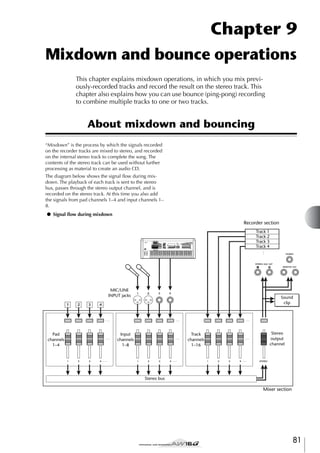

![Preparing for mixdown
To prepare for mixdown, select the track channels that
you will mix down, and adjust the balance and tone of
each track.
1
2
4
The MASTERING LIBRARY popup window will
appear. Turn the [DATA/JOG] dial to select the
desired library data, then move the cursor to the
RECALL button and press the [ENTER] key.
Lower the [STEREO] fader to the –∞ position.
In the Quick Navigate section, repeatedly
press the [RECORD] key or hold down the
[RECORD] key and use the CURSOR [ ]/[ ]
keys to access the MIXDOWN page of the
RECORD screen.
The MIXDOWN page is where you can perform
mixdown operations. In this page you can select the
channels that will be recorded via the stereo bus
onto the stereo track.
2
1
Tip!
The mastering library contains data for loading EQ/
dynamics settings into the stereo output channel. (For
details, refer to → p. 78)
3
5
4
If you want to use the mastering library,
move the cursor to the LIBRARY button and
press the [ENTER] key.
If you want to adjust the pan of each track
channel, repeatedly press the Selected Channel section [PAN/BAL] knob or hold down the
[PAN/BAL] knob and use the CURSOR [ ]/
[ ] keys to access the PAN page of the PAN
screen.
In this page you can set pairing, phase, and pan for
each channel.
1
1 REC button
Puts the stereo track in record-ready mode.
Defeats the record-ready state of the stereo track.
C LIBRARY button
Accesses the mastering library.
D Stereo bus
Indicates the on/off status of the channels being sent
to the stereo bus. The numbers within the screen
correspond to the following channels.
INPUT 1–8................. Input channels 1–8
P1–P4......................... Pad channels 1–4
TRACK 1–16 .............. Track channels 1–16
3
Use the [INPUT SEL] keys,
[TRACK SEL] keys, and pad
keys 1–4 to select the channels
that you want to send to the
stereo bus.
The screen will change as follows
each time you press a key or pad
repeatedly.
Tip!
• All channels will be turned on by default. However in
order to obtain the best S/N ratio, you should turn off
any channels that you are not using.
• You can also add the signals of the input channels or
pad channels to the mixdown (→ p. 89).
2
3
1 PAIR
Indicates the paired status of adjacent odd-numbered/even-numbered channels. A heart symbol
indicates channels that are paired, and a broken
heart symbol indicates channels that are not paired.
You can also set or defeat pairing in this page by
moving the cursor to a heart symbol and pressing
the [ENTER] key.
Note
Track channels 9/10–15/16 and pad channels 1–4 always
function as paired channels. Pairing cannot be defeated
for these channels.
B PHASE
Switches the phase of the signal of each channel
between normal and reversed. Move the cursor to
this location and press the [ENTER] key to switch
between N (Normal) and R (Reverse) phase.
C PAN
Adjusts the pan (the left/right position when the signal is sent to the stereo bus or L/R bus) of each
channel.
83
Mixdown and bounce operations
B SAFE button
9](https://image.slidesharecdn.com/aw16ge-131126034127-phpapp02/85/Aw16-ge-83-320.jpg)
![Mixdown and bounce operations
Note
• If the page is different than shown above, make sure
that you have selected track channels as the object of
operations. (This is indicated in the upper left of the
screen.) If input channels and pad channels are
selected, press any one of the [TRACK SEL] keys.
• Even if channels are paired, their phase and pan are not
linked. Set these parameters individually for each channel.
6
7
8
Raise the [STEREO] fader to the 0 dB position.
While you play back the song, raise the track
channel faders to an appropriate level. If necessary, adjust the EQ and dynamics of each
track channel.
You can adjust the track channel EQ/dynamics in a
similar way as for the input channels; press a
[TRACK SEL] key to select a track channel, and use
the Selected Channel section [EQ] knob and [DYN]
knob.
Move the cursor to the PAN knob of each
track channel, and turn the [DATA/JOG] dial
to adjust the pan setting.
Tip!
Another way of adjusting the pan is to press a [TRACK
SEL] key to select a track channel, and then turn the
[PAN/BAL] knob in the Selected Channel section. This
method is convenient when you want to adjust the pan
without displaying a different screen.
If you use the [PAN/BAL] knob to adjust the pan of track
channels 9/10–15/16, moving the knob will initially
cause only the pan value of one side to change. When
that pan value reaches the far right or left, the other pan
value will then begin to change.
Using the internal effects via send/return
You can use the internal effects via send/return to add
effects to the mixdown. As an example, here’s how to use
internal effect 1 in this way.
Tip!
If the page you see is different than shown above, make
sure that input channels are selected as the object of your
operations. (This is shown in the upper left of the screen.)
If track channels are selected, press one of the [INPUT
SEL] keys.
■ Internally connecting an internal
effect via send/return
The “Track recording” chapter explained how to insert an
internal effect into an input channel by using the input
library. If an insert effect has been inserted in a channel,
you must first “un-insert” that effect (cancel the insertion)
before you can use it in a send/return configuration.
1
2
Repeatedly press the [EFF1] knob or hold
down the [EFF1] knob and use the CURSOR
[ ]/[ ] keys to access the SEND page of the
EFF1 screen.
1
1 EFF INSERT
Inserts/cancels an insert effect for a specific channel. The display will indicate “on” for a channel into
which an effect is currently inserted.
Move the cursor to the EFF INSERT field of
the channel into which effect 1 is inserted,
and press the [ENTER] key.
A popup window will ask you to confirm that you
want to cancel (release) the effect insertion.
Press any [INPUT SEL] key to select an input
channel for operations.
The SEND page of the EFF1 screen will appear.
84
3
4
Move the cursor to the OK button and press
the [ENTER] key.
Insertion of insert effect 1 into that channel will be
cancelled, and now you are free to use this effect in
the mixer section via send/return.](https://image.slidesharecdn.com/aw16ge-131126034127-phpapp02/85/Aw16-ge-84-320.jpg)
![■ Adjusting the effect send level
Here’s how to load an effect library into internal effect 1,
and adjust the level (effect send level) of the signal that is
sent from each channel via effect bus 1 to internal effect
1.
1
Select the effect library that you want to use,
and load it into internal effect 1.
In this example, we will select a reverb-type library.
While you play back the song, move the cursor to the EFF knobs in the screen, and adjust
the level of the signal that is sent from each
channel to internal effect 1.
Tip!
Repeatedly press the [EFF1] knob or hold
down the [EFF1] knob and use the CURSOR
[ ]/[ ] keys to access the LIBRARY page of
the EFF1 screen.
2
5
Another way of adjusting the send level to internal effect
1 is to press a [TRACK SEL] key to select a track channel,
and then turn the [EFF1] knob of the Selected Channel
section. This method is convenient if you want to adjust
the effect level without displaying a different screen.
6
To adjust the master level of the effect send,
repeatedly press the Selected Channel section [VIEW] key or hold down the [VIEW] key
and use the CURSOR [ ]/[ ] keys to access
the BUS page of the VIEW screen.
The BUS page of the VIEW screen lets you use onscreen faders to adjust the master level of each bus.
3
Press the [EFF1] knob once to access the
SEND page of the EFF1 screen.
If insert effect 1 is connected via the mixer section
send/return, the following items will be added to
the SEND page of the EFF1 screen.
12
1
3
4
5
1 PEAK button
2
B PRE/POST button
This selects whether the level meters of the BUS
page will indicate the pre-fader level (PRE) or the
post-fader level (POST). This setting is independent
from the METER page of the VIEW screen.
1 EFF
Adjusts the send level of the signal that is sent from
each channel to insert effect 1.
B PRE/POST
Selects the location from which the signal from
each channel will be sent to insert effect 1. Move
the cursor to this area and press the [ENTER] key to
switch between the following two settings.
PRE (pre-fader) .......... The signal from immediately
before the fader will be sent.
POST (post-fader) ...... The signal from immediately after
the fader will be sent.
Note
If the page you see is different than shown above, make
sure that track channels are selected as the object of your
operations. (This is shown in the upper left of the screen.)
If input channels/pad channels are selected, press one of
the [TRACK SEL] keys.
4
Move the cursor to the PRE/POST field in the
screen, and press the [ENTER] key to specify
the location from which the signal will be
sent from each channel to internal effect 1.
C AUX
D EFF
E BUS
Use these faders to adjust the master levels of AUX
buses 1/2, effect buses 1/2, and the L/R bus. The
level of each bus is indicated by the level meters at
the right of each fader.
7
Move the cursor to the fader for effect bus 1,
and use the [DATA/JOG] dial to raise or lower
it.
Tip!
You can also adjust the level of the return signal that is
returned from the internal effect to the mixer section. For
details, refer to “Editing the parameters of an internal
effect” (→ p. 94).
Select POST if you want the volume of the effect
sound to be affected by the fader position. Select
PRE if you want to set the volume of the effect
sound independently of the fader position.
85
9
Mixdown and bounce operations
This is an on/off switch for the peak hold function of
the level meters. If this button is on, a peak indicator
will show the level meter peaks, and will
remain displayed. To reset this indicator, you can
temporarily switch the PEAK button off. This setting
is shared with the METER page of the VIEW screen.](https://image.slidesharecdn.com/aw16ge-131126034127-phpapp02/85/Aw16-ge-85-320.jpg)
![Mixdown and bounce operations
Recording on the stereo track
Here’s how to record the final mix on the stereo track.
1
In the Quick Navigate section, repeatedly
press the [RECORD] key or hold down the
[RECORD] key and use the CURSOR [ ]/[ ]
keys to access the MIXDOWN page of the
RECORD screen.
1 ST.TRACK ON/OFF button
Switches stereo track playback on/off.
B Virtual track
Selects the virtual track that is assigned to the stereo
track. The currently selected virtual track is indicated by a “●.” Of the other virtual tracks, those
that have already been recorded are indicated by
“O,” and the unrecorded tracks are indicated by “-”.
C Track view
In this area, markers and the presence or absence of
track data are displayed graphically.
D PRE/POST buttons
2
The panel [STEREO] key will blink red. This blinking indicates that the stereo track is in record-ready
mode.
3
These buttons select whether the level meter in the
ST.TRACK page will indicate the pre-fader level
(PRE) or the post-fader level (POST). This setting is
shared with the BUS page of the VIEW screen.
Move the cursor to the REC button of the
MIXDOWN page, and press the [ENTER] key
to turn the button on.
Press the RTZ [
] key to rewind the song.
Then hold down the REC [●] key and press
the PLAY [ ] key.
E Level meter
This indicates the output level of the stereo track.
6
The song will begin playing, and the playback will
be recorded on the stereo track.
Tip!
The data that is recorded here on the stereo track will be
the data that is used to create an audio CD. If you want
to precisely specify the beginning or end of the song, it is
convenient to use Auto Punch-in/out (→ p. 59).
4
5
To play back the stereo track, repeatedly
press the Quick Navigate section [MONITOR]
key or hold down the [MONITOR] key and
use the CURSOR [ ]/[ ] keys to access the
ST.TRACK page of the MONITOR screen.
1
2
4
86
3
5
When this button is on, the stereo track output will
be sent to a point directly before the [STEREO]
fader, and can be monitored from the STEREO/AUX
OUT jacks or the MONITOR OUT jacks. At this
time, the record-ready status of all tracks will be
cancelled.
Tip!
Even while the stereo track is playing, you can still monitor the signals from the input channels.
Note
When you reach the end of the song, move
the cursor to the SAFE button in the screen
and press the [ENTER] key.
A popup window will ask you to confirm that you
want to cancel record-ready mode. Move the cursor
to the OK button and press the [ENTER] key.
Switch the ST.TRACK ON/OFF button ON.
EQ and dynamics processing are applied to the playback
of the stereo track.
7
Press the RTZ [
] key to rewind the song,
and press the PLAY [ ] key.
The stereo track will be played back. Use the [STEREO] fader to adjust the monitor level.
When playback ends and you want to move to a
different screen, switch the ST.TRACK ON/OFF button OFF.
Tip!
If desired, you can use the [UNDO/REDO] button to cancel the recording that was made on the stereo track (→
p. 61), or use the ST.TRACK page to switch virtual tracks
and record another take (→ p. 62).](https://image.slidesharecdn.com/aw16ge-131126034127-phpapp02/85/Aw16-ge-86-320.jpg)
![Bounce (ping-pong) recording procedure
Here’s how to perform the bounce (ping-pong) recording
procedure, which lets you combine multiple tracks onto
one or two tracks.
1
2
3
Lower the [STEREO] fader to the –∞ position.
In the Quick Navigate section, repeatedly
press the [RECORD] key or hold down the
[RECORD] key and use the CURSOR [ ]/[ ]
keys to access the BOUNCE page of the
RECORD screen.
In the upper TRACK area,
select a bounce-source
track, move the cursor to
the symbol for that
track, and press the
[ENTER] key.
Each time you press the
[ENTER] key, the screen will
change as follows.
In the BOUNCE page you can select the bouncesource tracks, and record them via the L/R bus onto
one or two bounce-destination tracks.
51
2
Tip!
If a track channel is selected as a bounce-source, its
assignment to the stereo bus will automatically be turned
off.
43
1 TRACK (upper line)
Selects the bounce-source tracks.
The two horizontal lines indicate the L/R bus signal
route. This lets you see the on/off status of the signals that are sent from the bounce-source tracks,
and see the selected bounce-destination track(s).
C TRACK (lower line)
Select other bounce-source tracks in the
same way.
Use the [TRACK SEL] keys to select a bouncedestination track.
The [TRACK SEL] key will blink red, indicates that
the corresponding track is selected as the bouncedestination. A line will appear in the screen to indicate the connection to the track. (To cancel your
selection, press the same key once again.)
Here you can select the bounce-destination track(s).
D SAFE button
When you move the cursor to this button and press
the [ENTER] key, all bounce-source and bouncedestination assignments will be cancelled.
E BUS button
When you move the cursor to this button and press
the [ENTER] key, the right side of the screen will
show a fader for adjusting the output level of the L/R
bus, and a dedicated level meter for the L/R bus.
You can select up to two bounce-destination tracks.
If you select track 1, 3, 5, or 7, bus L will be connected. If you select track 2, 4, 6, or 8, bus R will be
connected. If you select track 9/10–15/16, bus L
will be connected to the odd-numbered track, and
bus R will be connected to the even-numbered
track.
Tip!
• If you move the cursor to the SAFE button and press the
[ENTER] key, all connections will be cancelled.
• EQ and dynamics settings will be “flat” for the track
channels of the tracks you select as the recording-destination.
• If you select an unpaired track, the pan of the track
channel will be at the center position. If you select
paired tracks, the pan of adjacent odd-numbered/evennumbered track channels will be spread to left and right
respectively.
87
9
Mixdown and bounce operations
B Bus L/R
4
5](https://image.slidesharecdn.com/aw16ge-131126034127-phpapp02/85/Aw16-ge-87-320.jpg)
![Mixdown and bounce operations
6
7
Raise the [STEREO] fader and the faders of
the track channel(s) you selected as the
bounce-destination to the 0 dB position.
While you play back the song, raise the faders of the bounce-source track channels to an
appropriate level. Adjust the pan, EQ, and
dynamics of each track channel as necessary.
Note
The bounce-destination faders will not affect the content
that is recorded. However, the bounce-source faders
specify the volume balance that will be recorded.
8
Press the RTZ [
] key to rewind the song.
Then hold down the REC [●] key and press
the PLAY [ ] key.
The song will begin playing back, and will be
recorded on the bounce-destination track(s).
9
When you reach the end of the song, stop
the song and press the RTZ [
] key to
rewind.
10
To check the recorded result, move the cursor to the SAFE button and press the [ENTER]
key to cancel the recording settings.
11
Access the ON/OFF page of the MONITOR
screen (→ p. 31), turn off all track channels
other than the bounce-destination, and press
the PLAY [ ] key.
Tip!
• If you attempt to change the screen or page without
using the SAFE button, a popup window asking “Clear
Current REC Setting?” will appear, asking you whether
it is ok to clear the current recording settings. Move the
cursor to the OK button and press the [ENTER] key.
• If desired, you can use the [UNDO/REDO] button to
cancel the bounce-recording operation (→ p. 61), or
switch the virtual track of the bounce-destination and
record another take (→ p. 62).
88](https://image.slidesharecdn.com/aw16ge-131126034127-phpapp02/85/Aw16-ge-88-320.jpg)
![Convenient functions during mixdown/
bounce operations
Here are some convenient functions that you can use
during mixdown or bounce operations.
5
Adding input signals or pad performances during mixdown
In the Selected Channel section, repeatedly
press the [VIEW] key or hold down the [VIEW]
key and use the CURSOR [ ]/[ ] keys to
access the FADER page of the VIEW screen.
In the FADER page of the VIEW screen, you can use
on-screen faders to adjust the faders (input level) of
each channel.
During mixdown, you can add signals from the input
channels or pad channels. For example, you could add a
performance from a workstation-type synthesizer (with
built-in sequencer) that is synchronized to the AW16G
song, or add sound effects that have been assigned to the
pads. To do this, perform the following steps after you
have completed “Preparing for mixdown” (→ p. 83).
1
2
Press the [INPUT SEL] key or pad that corresponds to the input channel or pad channel
you want to use, to add that channel as a
mixdown-source.
In the Selected Channel section, repeatedly
press the [PAN/BAL] knob or hold down the
[PAN/BAL] knob and use the CURSOR [ ]/
[ ] keys to access the PAN page of the PAN
screen.
2
1 ON/OFF buttons
These buttons switch each channel on/off.
B Faders
These faders adjust the input level of each channel.
6
While you play back the song, move the cursor to the on-screen faders and turn the
[DATA/JOG] dial to adjust the level of the
input channels/pad channels that you want
to use.
7
If necessary, adjust EQ, dynamics, and the
send level to the internal effects for each
input channel or pad channel.
Now you have completed the preparations for adding input channel or pad channel signals to the mixdown. Record the mixdown on the stereo channel
as described in “Recording on the stereo track” (→
p. 86).
Note
If the page you see is different than shown above, make
sure that input channels/pad channels are selected as the
object of your operations. (This is shown in the upper left
of the screen.) If track channels are selected, press one of
the [INPUT SEL] keys or pads.
4
Move the cursor to the PAN knob of the
channel you want to use, and turn the
[DATA/JOG] dial to adjust the pan setting.
89
9
Mixdown and bounce operations
3
In the Quick Navigate section, repeatedly
press the [RECORD] key or hold down the
[RECORD] key and use the CURSOR [ ]/[ ]
keys to access the MIXDOWN page of the
RECORD screen.
1](https://image.slidesharecdn.com/aw16ge-131126034127-phpapp02/85/Aw16-ge-89-320.jpg)
![Mixdown and bounce operations
Using meters to check the level
of each channel
Viewing all parameters for a certain channel
During mixdown or bouncing, you can watch meters
that indicate the input levels in a single screen. To do so,
repeatedly press the Selected Channel section [VIEW]
key or hold down the [VIEW] key and use the CURSOR
[ ]/[ ] keys to access the METER page of the VIEW
screen.
Sometimes you will want to see all mix parameters for a
certain channel in a single screen. To do this, repeatedly
press the Selected Channel section [VIEW] key or hold
down the [VIEW] key and use the CURSOR [ ]/[ ]
keys to access the CH VIEW page of the VIEW screen.
(Some items can also be edited from this page.)
In the METER page, the display will change depending
on the channel that is currently selected (shown in the
upper left of the screen). Press an [INPUT SEL] key to
view the meters for the input channels/pad channels, or
press a [TRACK SEL] key to view the meters for the track
channels.
The display in the CH VIEW page will change depending
on the currently selected channel (shown in the upper
left of the screen). Use the [INPUT SEL] keys, pads 1–4,
[TRACK SEL] keys, and [STEREO SEL] key to select the
channel that you want to view.
● If a track channel is selected
2 1
● If an input channel, pad channel, or track channel is
selected
1
3
● If an input channel/pad channel is selected
2 1
3
23 4 5 6 7 M KL
● If the stereo output channel is selected
1 PEAK button
This button switches the level meter peak hold function on/off. When this button is on, a
indicator
will show the peaks of the level meters, and this
indicator will be held. To reset the indicator, temporarily turn off the PEAK button. This setting is shared
with the BUS page of the VIEW screen.
B PRE/POST buttons
These buttons select whether the level meters in the
METER page will indicate the pre-fader levels (PRE)
or the post-fader levels (POST). This setting is independent from the BUS page of the VIEW screen.
C Level meters
These indicate the input level of each channel.
J 89
2
4 5 67 N L
1 Pairing
Indicates the pairing status of adjacent odd-numbered/even-numbered channels. Paired channels
are indicated by a heart-shaped symbol, and
unpaired channels are indicated by a broken heart.
Move the cursor here and press the [ENTER] key to
switch pairing on/off.
Note
Pairing cannot be switched off for track channels 9/10–
15/16, pad channels 1–4, and the stereo channel.
B ATT knob
Move the cursor to this knob and turn the [DATA/
JOG] dial to adjust the attenuation of the signal over
a range of 0 to –96 dB before it enters the EQ. This
is the same function as the ATT. knob in the EDIT
page of the EQ screen.
C Phase (except for the stereo output channel)
Move the cursor here and press the [ENTER] key to
switch the phase of the signal between N (Normal)
and R (Reverse).
90](https://image.slidesharecdn.com/aw16ge-131126034127-phpapp02/85/Aw16-ge-90-320.jpg)
![D Effect insert
N OUTPUT LEVEL (only for the stereo output
channel)
This lets you insert an internal effect into the channel. When you move the cursor here and press the
[ENTER] key, a popup window will appear, allowing you to select internal effect 1 or 2.
Move the cursor to this knob and turn the [DATA/
JOG] dial to adjust the output level of the signal that
is sent from the stereo output channel to the STEREO/AUX OUT jacks and MONITOR OUT jacks.
The range is –∞ to 0 dB.
E EQ
Move the cursor here and press the [ENTER] key to
switch EQ on/off.
Note
F DYN
The OUTPUT LEVEL knob will follow the operation of
the panel [STEREO FADER]. However, please note that if
you adjust the on-screen knob and then operate the panel
fader, the value will not change until the fader passes the
current value.
Move the cursor here and press the [ENTER] key to
switch dynamics on/off.
G ON/OFF
Move the cursor here and press the [ENTER] key to
switch the channel on/off.
H EFF1 (except for the stereo output channel)
I EFF2 (except for the stereo output channel)
J AUX1 (except for the stereo output channel)
K AUX2 (except for the stereo output channel)
Move the cursor to these knobs and turn the [DATA/
JOG] dial to adjust the send levels to effect buses 1/
2 and AUX buses 1/2.
By moving the cursor to the left of the knob and
pressing the [ENTER] key, you can switch between
pre-fader (send the pre-fader signal to the bus) and
post-fader (send the post-fader signal to the bus).
Initializing a channel
The mix parameters (EQ, dynamics, pan, etc.) of a channel can be reset to their default settings in a single operation. This function lets you start mixdown or bounce
operations with the track channels “zeroed,” and provides an easy way to reset the levels back to the nominal
setting if you can no longer hear any sound.
1
In the Quick Navigate section, repeatedly
press the [MONITOR] key or hold down the
[MONITOR] key and use the CURSOR [ ]/
[ ] keys to access the INIT page.
9
L PAN/BALANCE knob
In this page you can separately initialize the mix
parameters of input channels 1–8, pad channels 1–
4, or track channels 1–16.
M FADER knob (except for the stereo output
channel)
2
Move the cursor to this knob and turn the [DATA/
JOG] dial to adjust the level of the signal that is sent
from the channel to the stereo bus or L/R bus. The
range is –∞ to +6 dB.
Press the [INPUT SEL] key, pad, or [TRACK
SEL] key for the channel that you want to initialize.
When you press a key or pad, the upper line of the
screen will indicate “CH.PARAMETER INITIALIZED,” and the corresponding channel will be initialized. (Channel library 00 will be recalled.)
An initialized channel will have the following mix
parameter settings.
Note
The FADER knob of a track channel will follow the operation of the corresponding panel fader 1–8 or 9/10–15/16.
However, please note that if you adjust an on-screen
knob and then operate the panel fader, the value will not
change until the fader passes the current value.
Input channel
Pad channel
Track channel
Phase
no change
no change
no change
Attenuation
0 dB
0 dB
0 dB
EQ
ON
ON
ON
EQ parameters
flat
flat
flat
Dynamics on/off
OFF
OFF
OFF
Dynamics type
COMP
COMP
COMP
Dynamics
parameters
no effect
no effect
no effect
Pan
If paired: L channel = L16,
R channel = R16
If unpaired: center
L channel = L16
R channel = R16
If paired: L channel = L16,
R channel = R16
If unpaired: center
Fader
0 dB*
0 dB
no change*
* If FADER FLIP is set to TRACK in the UTILITY screen PREFER page.
91
Mixdown and bounce operations
Move the cursor to this knob and turn the [DATA/
JOG] dial to adjust the pan (or balance, in the case
of the stereo output channel) of the signal that is
sent from the channel to the stereo bus or L/R bus.](https://image.slidesharecdn.com/aw16ge-131126034127-phpapp02/85/Aw16-ge-91-320.jpg)
![Mixdown and bounce operations
Editing the EQ parameters
The chapters entitled “Track recording” and “Overdubbing” explained how to load an EQ library and use the
Selected Channel section [EQ] knob to make adjustments. Here’s how you can make more detailed adjustments to the EQ parameters.
1
If desired, load library data from the EQ
library.
Repeatedly press the Selected Channel section [EQ] knob or hold down the [EQ] knob
and use the CURSOR [ ]/[ ] keys to access
the EDIT page of the EQ screen.
The EDIT page of the EQ screen lets you edit all of
the EQ parameters.
6
2
3
4
To switch the HIGH band type, turn the
HIGH band Q knob all the way to the left.
7
To switch the EQ on/off, press the [ENTER]
key.
1 78
1 ON/OFF button
B Response curve
Graphically indicates the approximate response of
the EQ.
C FLAT button
Move the cursor to this button and press the
[ENTER] key to reset the boost/cut amount of all
bands to 0 dB.
D ATT. (Attenuation) knob
Attenuates the signal immediately before it is input
to the EQ, over a range of –96 to 0 dB. This is used
mainly to prevent the signal from clipping when
you use the EQ to boost a specific frequency region.
E Output meter
Indicates the level of the signal after it has passed
through the EQ.
F Q knobs
Specify the Q (steepness) at which each band
(HIGH, HI-MID, LO-MID, LOW) will be boosted or
cut. The range is 10–0.10, and higher settings will
produce a steeper curve.
G F (Frequency) knobs
Specify the center frequency of the boost/cut, over a
range of 21.2 Hz–20.0 kHz.
H G (Gain) knobs
Specify the amount of boost/cut, over a range of
–18.0 dB to +18.0 dB.
92
To switch the LOW band type, move the cursor to the LOW band Q knob and turn the
[DATA/JOG] dial toward the left.
6
5
Switches the EQ on/off.
Move the cursor to the parameter that you
want to edit, and use the [DATA/JOG] dial to
adjust the value.
With the default EQ settings, the LOW band is a
shelving type. (The value field for the Q knob will
indicate “L.SHL”.)
If you turn the Q knob toward the left, the Q knob
value field will change to a numerical value, and
will switch to the same boost/cut type as the HIMID and LO-MID bands.
If you continue turning the Q knob toward the left,
the Q knob value field will indicate “HPF,” and the
LOW band will function as a high-pass filter. If
“HPF” is selected, you can use the LOW band G
knob to switch the high-pass filter on/off.
Press an [INPUT SEL] key, a pad 1–4, a
[TRACK SEL] key, or the [STEREO SEL] key to
select the channel whose EQ you want to
adjust.
2
3
4
5
With the default EQ settings, the HIGH band is a
shelving type. (The value field for the Q knob will
indicate “H.SHL”.)
If you turn the Q knob toward the left, the Q knob
value field will change to a numerical value, and
will switch to the same boost/cut type as the HIMID and LO-MID bands.
If you continue turning the Q knob toward the left,
the Q knob value field will indicate “LPF,” and the
HIGH band will function as a low-pass filter. If
“LPF” is selected, you can use the HIGH band G
knob to switch the low-pass filter on/off.
In the EDIT page, you can press the [ENTER] key to
switch the EQ on/off (except when the cursor is
located at the FLAT button).
Tip!
• If the meter display clips because you boosted a certain
band, lower the ATT. knob to attenuate the signal.
• The [EQ] knob of the Selected Channel section will still
operate even while the EDIT page of the EQ screen is
displayed.](https://image.slidesharecdn.com/aw16ge-131126034127-phpapp02/85/Aw16-ge-92-320.jpg)
![Editing the dynamics parameters
Note
You can perform detailed editing of the dynamics parameters in the same way as for the EQ parameters.
You will not be able to select LEFT if you have selected
input channel 1, pad channel 1, track channel 1, or the
stereo output channel.
1
Press an [INPUT SEL] key, a pad 1–4, a
[TRACK SEL] key, or the [STEREO SEL] key to
select the channel whose dynamics parameters you want to edit.
2
3
From the dynamics library, recall the settings
that are closest to what you have in mind.
Repeatedly press the Selected Channel section [DYN] knob or hold down the [DYN]
knob and use the CURSOR [ ]/[ ] keys to
access the EDIT page of the DYN screen.
2
Tip!
Dynamics settings and operation are linked for paired
channels and for the stereo output channel. In this case,
dynamics processing will operate simultaneously for both
channels if either channel exceeds the threshold level.
E GR (Gain Reduction)
Indicates the amount of gain reduction produced by
the dynamics processor, in a range of –18 dB to
0 dB.
F Output meter
Indicates the level of the signal after it has passed
through the dynamics processor.
4
G Parameters
Here you can edit the parameters of the dynamics
processor. The type of parameters and their ranges
will differ depending on the dynamics processor
type. For details on the types of parameter and their
function, refer to the appendix.
1
3
7
56
1 ON/OFF button
Switches dynamics on/off.
B TYPE
COMP........................ Compressor
EXPAND..................... Expander
GATE.......................... Gate
COMPAND-H ............ Compander (hard)
COMPAND-S ............. Compander (soft)
DUCKING ................. Ducking
Move the cursor to the parameter that you
want to edit, and use the [DATA/JOG] dial to
edit the value.
To switch dynamics on/off, press the [ENTER]
key.
In the EDIT page, you can press the [ENTER] key to
switch dynamics on/off regardless of the cursor
location.
Please be aware that if you edit even one parameter
in the EDIT page of the DYN screen, the operation
of the Selected Channel section [DYN] knob will
change as follows for that channel.
Note
You cannot change the dynamics type in this page. If you
want to use a different type, you must recall library settings that use the desired type.
C Response curve
This graph indicates the approximate response of
dynamics settings. The horizontal axis of the graph
is the input level, and the vertical axis is the output
level.
D KEYIN SOURCE
Selects one of the following as the trigger signal
(key-in signal) that will control dynamics processing.
SELF ........................... The post-EQ signal of the currently
selected channel
LEFT ........................... The post-EQ signal of the adjacent
channel to the left
AUX1 ......................... The signal immediately before the
master send level of the AUX 1 bus
AUX2 ......................... The signal immediately before the
master send level of the AUX 2 bus
93
9
Mixdown and bounce operations
Indicates the currently selected dynamics type. The
displayed indication has the following meaning.
4
5](https://image.slidesharecdn.com/aw16ge-131126034127-phpapp02/85/Aw16-ge-93-320.jpg)
![Mixdown and bounce operations
1 Immediately after recalling a read-only library
that contains dynamics settings, turning the
[DYN] knob will simultaneously adjust multiple parameters to affect the dynamics processing. (The amount of change will depend
on the last-recalled library.)
Editing the parameters of an
internal effect
By using the EDIT page of the EFF1 screen or EFF2
screen, you can make detailed edits to the effect parameters of the internal effects 1 and 2.
If an effect is internally connected via send/return in the
mixer section, the parameters (EQ, pan, AUX send, etc.)
of the return channel that processes the return signal can
also be edited in this page.
As an example, here’s how you can edit the settings of
internal effect 1, internally connected via send/return.
1
For internal effect 1, recall an effect library
that uses the desired effect type.
2
In the Selected Channel section, repeatedly
press the [EFF1] knob or hold down the
[EFF1] knob and use the CURSOR [ ]/[ ]
keys to access the EDIT page of the EFF1
screen.
You cannot change the effect type (e.g., reverb,
delay) in the EDIT page. You must first recall library
settings that use the desired type.
The EDIT page lets you edit all of the effect parameters.
2
3
4
B For a channel for which you edited even one
parameter in the EDIT page of the DYN
screen, turning the [DYN] knob will adjust
only the last-edited parameter. (The lastedited parameter is remembered for each
channel.)
1
5
1 BYPASS ON/OFF button
Switches effect bypass on/off. The effect will not be
heard if this button is on.
B TYPE
Indicates the type of the currently selected effect.
Note
You cannot change the effect type in this page. If you
want to use a different type, you must recall library settings that use the desired effect type.
C STEREO/MONO
Indicates whether the effect is stereo or monaural. A
stereo-input effect is indicated by
, and a monaural-input effect is indicated by
.
D USED AS
C If you once again recall a read-only library
that contains dynamics settings, turning the
[DYN] knob will again simultaneously adjust
multiple parameters.
94
Indicates how this effect is being used. If the effect
is internally connected to the mixer section via
send/return, this will indicate “EFF1” or “EFF2.” If
the effect is inserted into a specific channel, this
will indicate the name of the channel into which
the effect is inserted (e.g., “INPUT 1”).](https://image.slidesharecdn.com/aw16ge-131126034127-phpapp02/85/Aw16-ge-94-320.jpg)
![E Parameter page/Return channel page
1 EFF2SEND
In this area you can edit the various effect parameters. The content and range of the parameters will
depend on the currently-used effect type.
If the effect is internally connected to the mixer section via send/return, this area will show the mix
parameters of the return channel, allowing you to
edit them.
3
Move the cursor to the effect parameter that
you want to edit, and turn the [DATA/JOG]
dial to edit the value.
Depending on the effect type, this area may be used
to show multiple parameter pages. In this case,
repeatedly press the CURSOR [ ] key to access
the parameter page that contains the parameter you
want to edit.
For example, the illustration below shows the
parameter pages for the STEREO DELAY effect type.
Adjusts the level at which the signal is sent from the
return channel to the other internal effect.
Note
You cannot send the signal from return channel 1 to
insert effect 1 (since this would mean sending the signal
back to the same effect itself). For this reason, the EDIT
page of the EFF1 screen has no send level to effect 1. For
the same reason, the EDIT page of the EFF2 screen has no
send level to effect 2.
B AUX1SEND
C AUX2SEND
These adjust the send level of the signal that is sent
from the return channel to AUX buses 1/2.
D EFF2 PRE/POST
Switches the signal that is sent from the return channel to the other effect bus between pre-fader and
post-fader.
E AUX1 PRE/POST
F AUX2 PRE/POST
These switch the signals that are sent from the
return channel to AUX buses 1/2 between pre-fader
and post-fader.
1
2
3
9
MIX BAL. parameter
Mixdown and bounce operations
Tip!
The parameter pages show the parameters that are specific to that effect type. However for all effect types, the
lower right of the last parameter page will have a MIX
BAL. parameter which sets the mix balance between the
effect sound and the original sound.
4
To edit the mix parameters of the return
channel, access the last parameter page, and
then press the CURSOR [ ] key once again.
If the effect is internally connected to the mixer section via send/return, you can repeatedly press the
CURSOR [ ] key to access the mix parameters of
the return channel. The following pages are the
same for all effect types.
1
4
2
5
3
4
1
B
C
D
E
F
5
6
EQ HIGH GAIN
EQ HIGH FREQ
EQ HIGH Q
EQ H-MID GAIN
EQ H-MID FREQ
EQ H-MID Q
These specify the gain, frequency, and Q for the
HIGH and HI-MID bands of the return channel EQ.
The range of each parameter is the same as in the
EDIT page of the EQ screen.
6
95](https://image.slidesharecdn.com/aw16ge-131126034127-phpapp02/85/Aw16-ge-95-320.jpg)
![Mixdown and bounce operations
2
1
3
Inserting an effect into a track
channel
The chapter “Track recording” explained how to insert an
internal effect into an input channel. In the same way,
you can also insert an effect into a track channel or pad
channel. As an example, here’s how to insert internal
effect 1 into a track channel for use during mixdown or
bouncing.
4
1
B
C
D
E
F
5
6
EQ L-MID GAIN
EQ L-MID FREQ
EQ L-MID Q
EQ LOW GAIN
EQ LOW FREQ
EQ LOW Q
1
In the Selected Channel section, repeatedly
press the [EFF1] knob or hold down the
[EFF1] knob and use the CURSOR [ ]/[ ]
keys to access the SEND page of the EFF1
screen.
These specify the gain, frequency, and Q for the LOMID and LOW bands of the return channel EQ. The
range of each parameter is the same as in the EDIT
page of the EQ screen.
Note
If the displayed page is different than shown above, make
sure that a track channel is selected as the object of operations. (This is indicated in the upper left of the screen.)
If an input channel/pad channel is selected, press any one
of the [TRACK SEL] keys.
1
2
3
2
1 PAN L
B PAN R
Move the cursor to the EFF INSERT field of
the track channel into which you want to
insert an effect, and press the [ENTER] key.
A popup window will appear, asking whether it is
ok to release internal effect 1 from the send/return
connection.
Independently specify the return channel panning
for the L and R channels.
C RETURN
Adjusts the input level for return channel 1.
5
6
Access the desired return channel page,
move the cursor to a parameter, and turn the
[DATA/JOG] dial.
To switch effect bypass on/off, press the
[ENTER] key.
In the EDIT page, you can press the [ENTER] key to
switch bypass on/off regardless of the current location.
3
4
5
6
Move the cursor to the OK button and press
the [ENTER] key.
Internal effect 1 will be inserted into the
selected track channel.
Press the [EFF1] knob twice to access the
LIBRARY page of the EFF1 screen.
Select the library that you want to use for
that channel.
Note
If you insert an internal effect into a channel, the SEND
page of the EFF1 screen will no longer show return channel pages 1–4. To adjust the balance between the original
sound and the effect sound, use the MIX BAL. parameter
that is shown in the last parameter page.
Tip!
You can also insert an effect by using the effect insert
field in the CH VIEW page of the VIEW screen (→ p. 91).
96](https://image.slidesharecdn.com/aw16ge-131126034127-phpapp02/85/Aw16-ge-96-320.jpg)
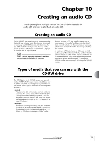

![Basic settings for the CD-RW drive
Before you actually write data to a CD, you will need to
make basic settings for the CD-RW drive.
1
2
In the Work Navigate section, repeatedly
press the [CD] key or hold down the [CD]
key and use the CURSOR [ ]/[ ] keys to
access the SETTING page of the CD screen.
1
2
4 5 3
6
You can select either x8 (eight times as fast as audio
playback) or x4 (four times as fast as audio playback). Normally you should use x8, and drop down
to x4 if errors occur during writing.
3
1 CD-RW MEDIA ERASE
Erases the data that was written to CD-RW media.
For details, refer to “Erasing CD-RW media” (→
p. 105).
Selects the speed at which audio data will be written to CD-R/RW media.
C TEST button
Specifies whether a writing test will be performed
when you execute writing.
D WRITE button
F DATA WRITE SPEED
This indicates the speed at which data other than
CD audio (e.g., backup data or WAV files) is written
to CD-R/RW media. Normally this will indicate x8.
This will indicate x4 if the media supports a maximum writing speed of x4. This field is for display
only, and cannot be edited.
G COMPARE button
4
If desired, set the UNDERRUN PROTECT button to ENABLE.
The CD-RW drive of the AW16G has a function to
prevent “buffer underrun” errors which can occur if
data transfer cannot keep up with the writing speed.
If you switch the UNDERRUN PROTECT button to
the “ENABLE” setting, this function will be enabled,
and buffer underruns will be prevented.
Note
If this button is set to ENABLE, the TEST button will automatically be turned off. Also, if the TEST button is turned
on, this button will automatically be set to DISABLE.
If this button is on, the original data will be compared with the backed-up data or the exported
WAV file after a backup or export operation is performed, to check whether any errors occurred while
writing the data.
H MOTOR ON ACCESS/DISC IN button
Selects one of the following two choices to specify
how the drive will operate when CD-R/RW media is
inserted.
ACCESS ...................... The drive will spin only when
access is required.
DISC IN ..................... The drive will spin whenever
media is inserted.
99
10
Creating an audio CD
Enables/disables the function that prevents buffer
underrun (an error that can occur when data transfer cannot keep up with writing speed).
The TEST button and WRITE button specify whether
a writing test and/or the actual writing operation
will be performed. The combination of buttons that
are on will determine the operation(s) that will
occur, as follows.
Depending on the media and the state of the hard
disk, it is possible that an error may occur while the
data is being written. (If you are using a CD-R, this
will make the media unusable.) Thus, you can turn
on the TEST button to check whether an error will
occur before you actually write the disc. If an error
occurs during the test, halt the procedure, and
either lower the writing speed or set the UNDERRUN PROTECT button to ENABLE.
B AUDIO WRITE SPEED
E UNDERRUN PROTECT button
Use the TEST button and WRITE button to
select the writing operation(s).
Only the TEST button on .........Only a writing test will be
performed.
Only the WRITE button on ......Writing will occur immediately.
Both the WRITE button and
TEST button on ...........First a writing test will be performed, and then the actual writing
will be performed.
8 7
Specifies whether the actual writing operation will
be performed.
Move the cursor to the AUDIO WRITE SPEED
field, and turn the [DATA/JOG] dial to select
the writing speed.](https://image.slidesharecdn.com/aw16ge-131126034127-phpapp02/85/Aw16-ge-99-320.jpg)
![Creating an audio CD
Writing audio data (Track At Once)
Here’s how to use the Track At Once method to write stereo tracks from songs saved on the hard disk to CD-R/RW
media. Use this method if you expect to be adding tracks
to the disc later, or if you want a two-second gap
between tracks.
1
3
A display like the following will appear.
3
Make sure that the appropriate virtual track is
selected for the stereo track of the song(s)
you want to write.
Only the virtual track that can be played by the stereo track (i.e., the “current track”) will be written to
disc. If the correct virtual track is not selected, load
that song, use the ST.TRACK page of the MONITOR
screen to switch to the correct virtual track, and
then save the song.
2
Insert CD-R/RW media in the drive, move the
cursor to the TRACK AT ONCE button, and
press the [ENTER] key.
Repeatedly press the [CD] key or hold down
the [CD] key and use the CURSOR [ ]/[ ]
keys to access the CD WRITE page of the CD
screen.
Immediately after you access this page, the
following two buttons will appear in the display.
2 6
1
54
1 Song list
This is a list of the songs containing stereo tracks
that will be written to the CD-R/RW media. The line
enclosed by a dotted frame is currently selected for
operations. If no songs have been registered, this
will indicate “-NO TRACK-”.
If audio data has already been written to the
inserted CD-R/RW media but the media has not yet
been finalized, a title of “--EXIST--” will be displayed for the already-written data.
12
B FINALIZE button
Finalizes the inserted media by writing track information to it.
C INS button
Inserts a new song in front of the song currently
selected in the list.
1 TRACK AT ONCE button
Creates an audio CD using the Track At Once
method.
D NEW button
Adds a song at the end of the song list.
B DISC AT ONCE button
Creates an audio CD using the Disc At Once
method.
E DEL button
Deletes the selected song from the list.
F EXECUTE button
Executes writing to the CD media.
Tip!
If you have inserted CD-RW media that contains data
written using other than the Track At Once method, a
popup window will appear immediately after step 3, asking whether you want to erase the data. If you want to
erase the entire media, move the cursor to the OK button. If you want to cancel creation of an audio CD, move
the cursor to the CANCEL button. Then press the
[ENTER] key.
4
100
Move the cursor to the NEW button, and
press the [ENTER] key.
The song list will show information (track number/
song name/size of the stereo track) for the song that
will be written to track 1 of the CD.](https://image.slidesharecdn.com/aw16ge-131126034127-phpapp02/85/Aw16-ge-100-320.jpg)
![5
Move the cursor to the dotted frame in the
song list, and turn the [DATA/JOG] dial to
select the song that will be written to track 1.
Note
• When you turn the [DATA/JOG] dial, you will see only
songs for which the current stereo track contains data.
• Songs with a stereo track shorter than four seconds will
not be displayed.
• Songs with a stereo track longer than 324 minutes will
not be displayed.
6
Repeat steps 4 and 5 to select the songs that
will be written to track 2 and following.
Tip!
• When you move the cursor to the NEW button and
press the [ENTER] key, a new song will be added at the
end of the existing songs.
• By using the INS button instead of the NEW button, you
can insert a new song immediately before the song that
is selected in the list.
• You can use the DEL button to delete the currently
selected song from the song list.
Note
When you add a song to the song list, the same song will
always be initially selected. Change this as desired.
7
Move the cursor to the EXECUTE button and
press the [ENTER] key.
8
To begin writing, move the cursor to the OK
button and press the [ENTER] key.
A popup window will ask you to confirm.
10
Creating an audio CD
While data is being written to the media, a popup
window will indicate “CD Writing...” When writing
is completed, a popup window will ask you
whether you want to finalize.
Note
• If an error message of “ATAPI Error!” appears while
writing, it is possible that a buffer underrun has
occurred. In this case, either decrease the writing speed
to 4x or set the UNDERRUN PROTECT button to the
ENABLE position. (→ p. 99)
• If you enabled the writing test in “Basic settings for the
CD-RW drive” (→ p. 99), a writing test will be performed before the data is actually written. If a problem
occurs during the writing test, an error message will
appear.
• Copy-prohibit data will automatically be written into
the CD that is created.
9
To finalize the disc, move the cursor to the
OK button and press the [ENTER] key.
If you do not want to finalize the disc, move the
cursor to the CANCEL button and press the [ENTER]
key.
This completes the writing process.
101](https://image.slidesharecdn.com/aw16ge-131126034127-phpapp02/85/Aw16-ge-101-320.jpg)
![Creating an audio CD
Writing audio data (Disc At Once)
Here’s how to use the Disc At Once method to write stereo tracks from songs saved on the hard disk to CD-R/RW
media. Use this method if you do not want to create
silence between each track of the CD, or if you want to
write a single song divided into multiple tracks on the
CD.
C INS button
1
2
E DEL button
3
4
Make sure that the appropriate virtual track is
selected for the stereo track of the song(s)
you want to write.
Inserts a new song in front of the song currently
selected in the list.
D NEW button
Adds a song at the end of the song list.
Deletes the selected song from the list.
F EXECUTE button
Executes writing to the CD media.
If you want to divide the song into CD tracks
at the marker locations specified within the
song, check that markers have been set at
the appropriate locations.
Repeatedly press the [CD] key or hold down
the [CD] key and use the CURSOR [ ]/[ ]
keys to access the CD WRITE page of the CD
screen.
Move the cursor to DISC AT ONCE and press
the [ENTER] key.
Tip!
If data has already been written on the CD-RW media
that you insert, a popup window will appear immediately
after step 3, asking whether you want to erase the data.
Move the cursor to the OK button if you want to erase
the entire media, or to the CANCEL button if you want to
cancel execution. Then press the [ENTER] key.
5
Move the cursor to the NEW button, and
press the [ENTER] key.
6
Move the cursor to the dotted frame in the
song list, and turn the [DATA/JOG] dial to
select the song that will be written to track 1.
Note
The following screen will appear.
3
• When you turn the [DATA/JOG] dial, you will see only
songs for which the current stereo track contains data.
• Songs with a stereo track shorter than four seconds will
not be displayed.
• Songs with a stereo track longer than 324 minutes will
not be displayed.
1
7
2 6
54
1 Song list
This is a list of the songs containing stereo tracks
that will be written to the CD-R/RW media. The line
enclosed by a dotted frame is currently selected for
operations. If no songs have been registered, this
will indicate “-NO TRACK-”.
B MARKER button
For each stereo track, this enables or disables the
markers that have been set within that song.
When you move the cursor to this button and press
the [ENTER] key, the start pint, end point and markers within the currently selected stereo track will be
enabled. (A “flag” icon will appear at the left of the
list.) If markers are enabled for a stereo track, a track
number will be written to the CD at the location of
each marker. Regardless of any areas of silence, the
entire region from the Start point to the End point
will be written.
102
The song list will show information (track number/
song name/size of the stereo track) for the song that
will be written to track 1 of the CD.
If you want the stereo track of the selected
song to be divided into CD tracks at the location of each marker, move the cursor to the
MARKER button and press the [ENTER] key.
Markers will be enabled for that song, and a “flag”
icon will appear at the right of the list.
Tip!
• Markers can be enabled/disabled independently for
each song.
• When you use markers to divide a stereo track, the
location of the divisions will be specified in units of 1/
75 second.
Note
• Note that if markers are enabled, the track numbers
shown in the list will not match the number of tracks
written to the CD.
• A maximum of 99 tracks can be written to an audio CD.
If, for example, markers are enabled for the song you
write to CD track 1, and this song contains 98 markers,
it will not be possible to write any more songs to that
CD-R/RW media.](https://image.slidesharecdn.com/aw16ge-131126034127-phpapp02/85/Aw16-ge-102-320.jpg)
![8
Repeat steps 5–7 to select the songs that will
be written to track 2 and following.
Tip!
• When you move the cursor to the NEW button and
press the [ENTER] key, a new song will be added at the
end of the existing songs.
• By using the INS button instead of the NEW button, you
can insert a new song immediately before the song that
is selected in the list.
• You can use the DEL button to delete the currently
selected song from the song list.
Note
When you add a song to the song list, the same song will
always be initially selected. Change this as desired.
9
Move the cursor to the EXECUTE button and
press the [ENTER] key.
10
To begin writing, move the cursor to the OK
button and press the [ENTER] key.
A popup window will ask you to confirm.
While data is being written to the media, a popup
window will indicate “CD Writing...” When writing
is completed, the CD-R/RW media will be ejected,
and the following popup window will appear.
10
Note
11
Creating an audio CD
• If you enabled the writing test in “Basic settings for the
CD-RW drive” (→ p. 99), a writing test will be performed before the data is actually written. If a problem
occurs during the writing test, an error message will
appear.
• Copy-prohibit data will automatically be written into
the CD that is created.
If you want to create another CD with the
identical contents, insert a new volume of
media, and move the cursor to the OK button and press the [ENTER] key.
Writing will begin again.
Alternatively, you can move the cursor to the CANCEL button and press the [ENTER] key to exit the
writing process.
103](https://image.slidesharecdn.com/aw16ge-131126034127-phpapp02/85/Aw16-ge-103-320.jpg)
![Creating an audio CD
Finalizing CD-R/RW media
Here’s how to finalize CD-R/RW media that you wrote
using Track At Once, so that the disc can be played by a
CD-RW drive or a CD player.
Tip!
CD-R/RW media written by the AW16G using Track At
Once (and not yet finalized) cannot be played by another
CD-RW drive or a CD player, but it can be played by the
AW16G’s CD Play function. (→ p. 106)
1
2
Insert the CD-R/RW media that you want to
finalize into the CD-RW drive.
3
Move the cursor to the TRACK AT ONCE button, and press the [ENTER] key.
4
Move the cursor to the FINALIZE button, and
press the [ENTER] key.
5
To finalize the disc, move the cursor to the
OK button and press the [ENTER] key.
Repeatedly press the [CD] key or hold down
the [CD] key and use the CURSOR [ ]/[ ]
keys to access the CD WRITE page of the CD
screen.
The following screen will appear, and the track list
will show the content that has been written to that
CD-R/RW media. Already-recorded tracks will be
displayed as “--EXIST--”.
A popup window will ask you to confirm the finalize operation.
If you decide not to finalize the disc, move the cursor to the CANCEL button and press the [ENTER]
key.
Note
The finalize operation cannot be halted once it has been
started. Perform this operation with care.
104](https://image.slidesharecdn.com/aw16ge-131126034127-phpapp02/85/Aw16-ge-104-320.jpg)
![Erasing CD-RW media
Here’s how to erase all data that has been written to CDRW media, so that the CD-RW disc can be used as a
blank disc. You will need to perform this operation on a
disc that has been used to store computer data etc. if you
want to use that disc on the AW16G.
Tip!
3
To execute the erasure, move the cursor to
the OK button. If you decide not to erase the
disc, move the cursor to the CANCEL button.
Then press the [ENTER] key.
If you selected the OK button, erasure will begin.
(This operation cannot be halted.)
Since data is erased as necessary when you back up
AW16G data to CD-RW media or when you write audio
data to CD-RW media, you do not need to perform the
following procedure each time you re-use the disc.
Note
The erased data cannot be recovered. Perform this operation with care.
1
In the Work Navigate section, repeatedly
press the [CD] key or hold down the [CD]
key and use the CURSOR [ ]/[ ] keys to
access the SETTING page of the CD screen.
2
Move the cursor to the CD-RW MEDIA ERASE
field, and press the [ENTER] key to select the
desired erasure method.
Each button selects the following erasure method.
10
Creating an audio CD
SIMPLY button ........... Only the TOC (Table Of Contents)
data written to the CD-RW media
will be erased. If you select this
method, it will take only a short
time to erase the CD-RW media.
PERFECTLY button ..... All data written to the CD-RW
media will be erased completely.
Since this method erases all data
from the media, it will take a
longer time than SIMPLY.
Move the cursor to the desired button, and press the
[ENTER] key. A popup window will ask you to confirm the erasure.
● If you turn on the SIMPLY button
● If you turn on the PERFECTLY button
105](https://image.slidesharecdn.com/aw16ge-131126034127-phpapp02/85/Aw16-ge-105-320.jpg)
![Creating an audio CD
Playing an audio CD
You can use the CD-RW drive to play back a conventional audio CD or CD-R/RW media to which audio data
has been written. This is referred to as the CD Play function.
4
Tip!
The CD Play function can also play audio data from a
mixed-mode CD-ROM (only track 2 and following) or CD
Extra (only the first session).
1
To play the CD tracks, press the PLAY [
key. To stop, press the STOP [■] key.
During playback, the audio output of the CD-RW
drive will be sent directly to the stereo output channel. Use the STEREO fader to adjust the volume.
When the CD Play function is on, the keys of the
transport section will have the following functions.
Key
PLAY [
In the Work Navigate section, repeatedly
press the [CD] key or hold down the [CD]
key and use the CURSOR [ ]/[ ] keys to
access the CD PLAY page of the CD screen.
] key
REW [
Operation
Play
STOP [■] key
Stop
] key/FF [
] key Rewind/Fast-forward
[DATA/JOG] dial
Select tracks
[
In this page you can play back an audio CD
inserted in the CD-RW drive.
]
Select tracks
] key/[
] key
Tip!
• When the cursor is located in the list, you can turn the
[DATA/JOG] dial to select tracks.
• While an audio CD is playing, the access indicator in
the display section will blink.
2 1
3
1 CD PLAY button
Switches the CD Play function on/off.
B INPUT CH MUTE/MIX button
Use this button to specify whether the signals of
input channels 1–8 will be output together with the
CD playback (MIX button), or whether only the CD
signal will be output (MUTE button).
C List
Displays the tracks of the audio CD that is inserted
in the CD-RW drive.
2
3
106
Insert the audio CD that you want to play
into the CD-RW drive.
Move the cursor to the CD PLAY button and
press the [ENTER] key.
The CD Play function will be turned on, and the CD
track data will be read.
5
To exit the CD Play function, move the cursor
to the CD PLAY button and press the [ENTER]
key.
Note
• The CD PLAY button can be switched on/off only while
the CD is stopped.
• While the CD PLAY button is on, the CD-RW drive will
be locked, and it will not be possible to eject the disc.](https://image.slidesharecdn.com/aw16ge-131126034127-phpapp02/85/Aw16-ge-106-320.jpg)
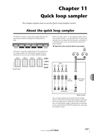

![Using sample libraries
Sample libraries contain sets of up to sixteen different
samples that can be used by the Quick Loop Sampler.
When the AW16G is shipped from the factory, sets of
samples such as drum loops and sounds effects are
stored on the hard disk as sample libraries. When you
load one of these libraries, samples will be assigned to
each pad/sample bank, and you can use the pads to play
the samples immediately. Here’s how to load a sample
library and try it out.
1
In the Quick Loop Sampler section, either
repeatedly press the [SAMPLE EDIT] key or
hold down the [SAMPLE EDIT] key and use
the CURSOR [ ]/[ ] keys to access the
LIBRARY page of the SAMPLE screen.
3
2
5 7
4
2
By turning on the LISTEN button and pressing a pad
1–4, you can audition the samples that are assigned
to sample bank A for each pad in that library. For
details on the library contents, refer to “Appendix.”
3
1 List
This area displays a list of the sample libraries saved
on the hard disk.
B NAME/OLD/SIZE buttons
These buttons sort the sample libraries shown in the
list, either alphabetically (NAME), by when they
were saved (OLD), or by their size (SIZE).
C LISTEN button
Tip!
D RECALL button
This button recalls the library that is selected in the
list, and assigns the samples to each pad/sample
bank.
E DELETE button
This button deletes the library selected in the list
from the hard disk.
F STORE button
When the popup window is open, you can move the cursor to the 1SAMPLE button and press the [ENTER] key to
select and load just a single sample from the library.
4
5
Raise the [STEREO] fader to the 0 dB position.
Strike pads 1–4.
You can play the samples that are assigned to sample bank A of each pad.
Tip!
Of the sample libraries saved on the hard disk when the
AW16G is shipped, most drum pattern libraries that are
set to Loop mode have the Slice function turned on. If
you load this type of library, you only need to press the
pad, and the tempo of the drum pattern will match the
tempo of the song. This lets you use the Quick Loop Sampler similarly to a drum machine.
Note
• If a sample is assigned to a pad, that pad will light while
the sample plays when you press it. However if no sample is assigned, nothing will play and the pad will not
light. You can either assign a sample to the pad, or
switch the sample bank.
• If the pad lights when you strike a pad but you hear no
sound, access the METER page of the VIEW screen, and
check whether the meter of the corresponding pad
channel (P1–P4) is moving (→ p. 90).
• If the meter moves when you strike a pad, make sure
that the [STEREO] fader has not been lowered, and that
your monitor system is connected correctly and that its
volume is set appropriately.
• If you hear no sound even after raising the [STEREO]
fader, access the INIT page of the MONITOR screen
and press that pad. This will initialize the pad channel
so that it will produce sound. (→ p. 91)
This button stores a library that you edited.
G PROTECT button
Move the cursor to this button and press the
[ENTER] key to switch the Protect setting on/off for
the library selected in the list. A lock icon will be
displayed to indicate a library that is protected, and
it will not be possible to edit or delete this library.
H NEW button
This button creates a new library on the hard disk.
109
11
Quick loop sampler
When you move the cursor to this button and press
the [ENTER] key, the button will be highlighted. If
you now press a pad 1–4, the sample assigned to
sample bank A of the currently selected sample
library will play repeatedly. Playback will stop
when you press the pad once again.
Move the cursor to the RECALL button and
press the [ENTER] key. A popup window will
open. Move the cursor to the ALL button,
and press the [ENTER] key.
When the library has been loaded, the popup window will automatically close.
1
86
Move the cursor into the list, and turn the
[DATA/JOG] dial to select the library that you
want to load.](https://image.slidesharecdn.com/aw16ge-131126034127-phpapp02/85/Aw16-ge-109-320.jpg)
![Quick loop sampler
6
7
Move the cursor to the bank area for the
desired pad, and turn the [DATA/JOG] dial.
8
To switch the sample bank for each pad,
repeatedly press the [SAMPLE EDIT] key to
access the SETUP page of the SAMPLE screen.
As desired, use the knobs and keys of the
Selected Channel section to process the
sound of pads 1–4.
1 23
The sample bank will change, and the sample name
will change accordingly.
EQ, dynamics, and effect send 1/2 levels can be
adjusted for the pad channels in the same way as
for the track channels or input channels. Press a pad
1–4 to select the pad channel that you want to control, and use the knobs and keys of the Selected
Channel section.
1 One shot/loop mode
An icon indicates whether the sample assigned to
the pad is set to One Shot mode ( ) or Loop mode
( ).
Tip!
B Pad number
• When you press a pad 1–4, the assigned sample will
always sound. If you want to select a pad for operations
without making it sound, hold down the [PAD SEL] key
and press a pad 1–4.
• The playback sounds of pads 1–4 are sent via pad channels 1–4 to the stereo bus. By using the MIXDOWN
page of the RECORD screen, you can record your pad
performance on the stereo track (→ p. 89). A recording
on the stereo track can also be moved to an audio track
(→ p. 128).
This indicates the pad number 1–4.
C Bank
This selects the sample bank (A–D) used by each
pad. The name of the sample assigned to that bank
is displayed at the right.
Tip!
If no sample is assigned to the selected bank, the sample
name area will indicate [-NO REC-].
Recording/playing a pad performance
Here’s how you can record your pad performance (pad
events) onto the pad tracks.
1
C Track status button
This indicates the operating state of the track. If you
move the cursor to this button and press the
[ENTER] key, the following two displays will alternate.
In the Quick Navigation section, repeatedly
press the [RECORD] key or hold down the
[RECORD] key and use the CURSOR [ ]/[ ]
keys to access the PAD page of the RECORD
screen.
..............................The pad track can be recorded.
..............................The pad track can be played.
Note
In the PAD page you can record pad events on the
pad tracks.
1 2
3
Depending on the settings in the PAD page of the TRACK
screen, this may also indicate
(muted).
4
D Pad track view
In this area, the pad events recorded in the pad
track are shown as a bar graph. Locator positions
are shown as icons in the lower part of the screen.
2
1 One Shot/Loop mode
An icon indicates whether the sample assigned to
the pad is set to One Shot mode ( ) or Loop mode
( ).
Tip!
B Pad track number
This shows the pad track number 1–4. At the right is
shown the name of the sample for the sample bank
selected for that pad.
110
Move the cursor to the track status button,
and press the [ENTER] key several times to
switch the button display to
(ready to
record). (You may select more than one pad
track.)
The track status button can be switched only when the
recorder is stopped.
3
4
Use the track channel faders and the [STEREO] fader to set the audio tracks to an
appropriate level for monitoring.
Locate the song to the point at which you
want to begin recording.](https://image.slidesharecdn.com/aw16ge-131126034127-phpapp02/85/Aw16-ge-110-320.jpg)
![5
To begin recording on the pad track, press
the PLAY [ ] key.
6
Play the pads while you listen to the audio
tracks play back.
C Track mute button
This button switches muting on/off for each track.
Move the cursor to this button and press the
[ENTER] key to switch between the following two
settings.
The recording will begin running, and pad event
recording will begin.
Pad events will be recorded on the pad tracks. The
pad events that are recorded will appear in the pad
track view in realtime.
Tip!
Pad tracks record only the pad on/off status.
7
8
To stop recording, press the STOP [■] key.
9
..............................The pad track can be played.
..............................The pad track is muted.
11
Move the cursor to the track mute button for
the track that you want to mute, and press
the [ENTER] key to switch the button to
(muted).
To cancel muting, move the cursor to the track mute
button and press the [ENTER] key once again.
Locate to the point from which you want to
start playing back, and press the PLAY [ ]
key.
The recorder will stop.
Tip!
To play back the events that were recorded
on the pad tracks, move the cursor to the
track status button and press the [ENTER] key
several times to switch the display to .
If a pad track is muted and the pad is set to LOOP/TRIGGER, the pad will play if you simply press the [PLAY] key
to play back the recorder. This means that you can use
this feature as a rhythm machine even without recording
on a pad track.
The pad track(s) will play back in synchronization
with the recorder. If you want to re-do the recording, repeat steps 6–9.
It is also possible to re-record just a specific region
of a pad track. In this case, the newly recorded pad
events will overwrite the previously-recorded
events. However, you need to be careful, since this
will also affect any overlapping pad events before
or after the re-recorded region.
Tip!
The contents of a recorded pad track can be edited in a
variety of ways using editing commands. For details, refer
to “What you can do using editing commands” (→
p. 123).
Quick loop sampler
10
11
If you want to mute a specific pad track,
press the Work Navigate section [TRACK] key
repeatedly or hold down the [TRACK] key
and use the CURSOR [ ]/[ ] keys to access
the PAD page of the TRACK screen.
In the PAD page of the TRACK screen you can
switch muting on/off for each pad track.
1 2
3
1 One Shot/Loop mode
An icon indicates whether the sample assigned to
the pad is set to One Shot mode ( ) or Loop mode
( ).
B Pad track number
This indicates the pad track number 1–4. At the
right is displayed the name of the sample assigned
to the sample bank selected for that pad.
111](https://image.slidesharecdn.com/aw16ge-131126034127-phpapp02/85/Aw16-ge-111-320.jpg)
![Quick loop sampler
Importing from an audio CD/WAV file to a
pad
Here’s how you can import CD audio data (CD-DA) or a
WAV file from a CD-ROM/CD-R into a sample bank for
pads 1–4.
1
1
2
3
Switch the internal settings of the AW16G to
enable digital recording.
2
● When importing from an audio CD/CD-Extra
Insert a CD into the CD-RW drive.
For details on digital recording settings, refer to
page 160.
You can load audio data (CD-DA) or WAV files from
the following types of media.
● Audio data (CD-DA)
• Audio CD
• CD-Extra (only the first session of CD-DA)
• Mixed Mode CD (only CD-DA data of the second and later tracks)
● WAV files
• ISO9660 Level 1 format CD-ROM, CD-R, CDRW*
• Mixed Mode CD
* The directory name and file name cannot use
characters other than uppercase alphanumeric
characters and the “_” (underscore) character. If
you use the AW16G to export WAV files onto CDR/RW media, the data will be in ISO9660 Level 1
format, but please be aware of this restriction if
you use a computer to create WAV files.
3
In the Quick Loop Sampler section, repeatedly press the [SAMPLE EDIT] key or hold
down the [SAMPLE EDIT] key and use the
CURSOR [ ]/[ ] keys to access the CD
IMPORT page of the SAMPLE screen.
5
6
7
4
1 From CD TRACK
Specifies the number (01–99) of the audio track that
will be imported from the source CD.
B From Start
Specifies the starting location of the data that will
be imported, in units of minutes/seconds/frames (1/
75th of a second).
C From End
Specifies the ending location of the data that will be
imported, in units of minutes/seconds/frames (1/
75th of a second).
Tip!
The “frames” here are the smallest unit of time used by a
CD track. Do not confuse them with the frames used in
MTC or SMPTE.
D LISTEN button
If you move the cursor to this button and press the
[ENTER] key, the specified region of the currently
selected CD track will be played back repeatedly.
E To PAD
Selects the pad number (1–4) to which the audio
material will be imported.
F To BANK
4
Selects the sample bank (A–D) to which the audio
material will be imported.
Make sure that the cursor is located at the
READ CD INFO button, and press the
[ENTER] key.
The display will indicate “Read CD info...”, and the
AW16G will begin reading the CD that is inserted
in the CD-RW drive.
Depending on the source from which data is read,
the screen will change as follows.
112
G To NAME
Indicates the name of the sample that is currently
assigned to the import-destination sample bank. If
nothing is assigned, this will indicate [-NO REC-].
This field is only for display, and cannot be edited.](https://image.slidesharecdn.com/aw16ge-131126034127-phpapp02/85/Aw16-ge-112-320.jpg)
![● When importing from a WAV file
2
1
• When you move the cursor to the LISTEN button and
press the [ENTER] key, there will be a slight interval of
time before you hear the sound, since the data is being
read from CD.
3
5
5
6
7
To move to a lower-level folder, display the ( )
icon in this area, move the cursor to the ENTER button in the screen, and press the [ENTER] key.
To move to the folder above, display the ( ) in this
area, move the cursor to the UP button in the
screen, and press the [ENTER] key.
4
1 From WAV File
Specifies the WAV file that will be imported. If the
media contains folders (directories), move to the
folder that contains the WAV file you want to
import, and then specify the desired WAV file.
The following icons will be displayed.
............................. Indicates that a WAV file is
selected.
............................. Indicates that a folder in the same
level is selected.
............................. Indicates that the folder for the
next higher level is selected.
6
If you are importing from an audio CD or
CD-Extra, use the From Start/From End fields
to specify the region that you want to
import.
7
Use the To PAD and To BANK fields to specify
the pad/sample bank into which the data will
be imported.
Note
B Mono/Stereo
If the import destination already contains data, the existing sample will be overwritten by the newly imported
sample. Be careful that you do not accidentally erase a
sample that you want to keep.
Indicates whether the WAV file selected for importing is monaural (M) or stereo (S). This field is only
for display, and cannot be edited.
C Size
Indicates the size (length in msec units) of the WAV
file selected for importing. This field is only for display, and cannot be edited.
If you are importing a WAV file, move the
cursor to the From WAVE file field, and turn
the [DATA/JOG] dial to select the WAV file
that you want to import.
8
When you have finished specifying the data
to be imported, move the cursor to the EXEC
button and press the [ENTER] key.
A popup window will appear, asking you to confirm
the operation.
D LISTEN/ENTER/UP buttons
The name and function of the button displayed here
will depend on the item that you select for the From
WAV File parameter.
● If WAV file ( ) is selected
The LISTEN button will be displayed, allowing you to
hear the WAV file repeatedly.
● If the next higher folder ( ) is selected
The UP button will be displayed, allowing you to
move to the folder above.
E To PAD
F To BANK
G To NAME
These have the same function as when importing
from an audio CD/CD-Extra.
Tip!
• If a mixed mode format CD-ROM is inserted in the CDRW drive, a popup window will appear, allowing you to
select AUDIO (CD-DA) or WAVE (WAV files) for
importing. Move the cursor to the button for the type of
data that you want to import, and press the [ENTER]
key.
• The only type of WAV files that can be imported are 16
bit/44.1 kHz monaural or stereo files.
• If you import a monaural WAV file, the same sample
will be assigned to the L and R channels.
9
Importing will begin. If you decide to cancel the
import, move the cursor to the CANCEL button and
press the [ENTER] key.
Tip!
• When you import from CD-DA, a name of “PAD_x_y”
(x= pad number, y= sample bank) will automatically be
assigned to the sample. You are free to change this
name later (→ p. 117).
• When you import a WAV file, the first eight characters
(not including the extension) of that filename will be
assigned as the name of the sample.
• The imported sample will be saved together with the
current song.
Note
It is not possible to import samples while the AW16G is
running.
113
11
Quick loop sampler
● If a folder in the same level is selected
The ENTER button will be displayed, allowing you to
move into that folder.
To execute the import, move the cursor to
the OK button and press the [ENTER] key.](https://image.slidesharecdn.com/aw16ge-131126034127-phpapp02/85/Aw16-ge-113-320.jpg)
![Quick loop sampler
Importing from an audio track/stereo track
to a pad
Here’s how a region of an already-recorded track of the
current song can be imported into a sample bank for
pads 1–4.
1
2
STEREO ......................Import stereo audio from the stereo
track.
Tip!
Play back the song, and find the track and
region that you want to import.
In the Quick Loop Sampler section, repeatedly press the [SAMPLE EDIT] key or hold
down the [SAMPLE EDIT] key and use the
CURSOR [ ]/[ ] keys to access the TR
IMPORT page of the SAMPLE screen.
1 2
3
4
If you import monaural audio from a track 1–16, the
same sample will be assigned to the left and right channels.
4
5
Move the cursor to the V.TR field, and turn
the [DATA/JOG] dial to select a virtual track
1–8 as the import destination.
Move the cursor to the From Start and From
End fields, and turn the [DATA/JOG] dial to
specify the start and end of the region that
will be imported.
The units by which you specify the location will
depend on the current counter display method. For
details on the counter display, refer to page 139.
5
6
7
6
Move the cursor to the To PAD and To BANK
fields, and turn the [DATA/JOG] dial to specify the pad number and sample bank into
which the data will be imported.
7
When you have finished making the settings,
move the cursor to the EXEC button and
press the [ENTER] key.
This page contains the following items.
1 From TRACK
Specifies the track from which the data will be
imported.
A popup window will ask you to confirm the operation.
B From V.TR
Specifies the virtual track from which the data will
be imported.
C From Start
Specifies the beginning of the region that will be
imported.
D From End
Specifies the end of the region that will be
imported.
E To PAD
Selects the pad (1–4) to which the data will be
imported.
F To BANK
Selects the sample bank (A–D) to which the data
will be imported.
G NAME
Indicates the name of the sample that is currently
assigned to the sample bank you specified as the
import destination. If no sample is currently
assigned, this will indicate [-NO REC-]. This item is
for display only, and cannot be edited.
3
Move the cursor to the From TRACK field,
and turn the [DATA/JOG] dial to select one of
the following as the import source track.
1–16........................... Import monaural audio from a
track 1–16.
1/2–15/16 .................. Import stereo audio from tracks 1/
2–15/16.
114
8
To execute the import, move the cursor to
the OK button and press the [ENTER] key.
The data will begin being read from the track. If you
decide to cancel the import operation, move the
cursor to the CANCEL button and press the [ENTER]
key.
Tip!
• The imported sample will be assigned the same name as
the track from which the data was imported. You are
free to edit this name later (→ p. 117).
• The imported sample is saved together with the current
song.
Note
• A total of up to 44 seconds (stereo) of samples can be
imported into the Quick Loop Sampler. If you specify a
region that exceeds this amount, an error message will
be displayed, and the import operation cannot be executed.
• If you import once again into the same pad and sample
bank, that sample will be overwritten by the newly
imported data. If you want to keep the previouslyimported sample, you must import the new data into a
different pad or sample bank.
• It is not possible to import samples while the AW16G is
running.](https://image.slidesharecdn.com/aw16ge-131126034127-phpapp02/85/Aw16-ge-114-320.jpg)
![Sampling an external input signal
You can directly sample (record) an input signal from the
MIC/LINE INPUT jacks and assign it to a pad. There are
two ways to do this; “manual record” in which you start
and stop recording manually, and “auto record” in which
recording will begin automatically when the signal
reaches a specified level.
3
The input channel will be connected directly to the
pad you specify. The PAD and NAME fields will
change accordingly.
■ Prepare for sampling
1
2
Press the [INPUT SEL] key of the input channel to which you connected the instrument
or mic, and then press the pad that you want
to specify as the record-destination.
Connect the instrument/mic that you want
to sample to a MIC/LINE INPUT jack.
In the Quick Navigate section, repeatedly
press the [RECORD] key or hold down the
[RECORD] key and use the CURSOR [ ]/[ ]
keys to access the SAMPLE page of the
RECORD screen.
1
4
Normally, one input channel will be connected to
channels L and R of the pad, as shown in the above
diagram. However if the input channels are paired,
the odd-numbered channel will be connected to
channel L of the pad, and the even-numbered channel will be connected to channel R of the pad.
5 6
Note
2 3
7 9
8
When you connect an input channel and a pad, the
counter display will change. In this state it will no longer
be possible to sound the pad, nor to operate the keys of
the transport section or the locate section.
When you move the cursor to the SAFE button and press
the [ENTER] key to cancel the connection, operation will
return to the normal state.
J
This page contains the following items.
1 INPUT
Indicates the connection status of input channels 1–
8.
B SAFE button
When you move the cursor to this button and press
the [ENTER] key, all connections will be cancelled.
Indicates the connection status of pads 1–4.
D PAD
Indicates the record-destination pad (1–4).
E BANK
Indicates the record-destination sample bank (A–D).
F Sample name
Indicates the sample that is currently assigned to the
sample bank selected in the PAD/BANK fields.
G MANU REC/AUTO REC button
Adjust the input level of the instrument or
mic.
5
As necessary, load an input library to create
the desired sound.
For details on how to adjust the level, refer to page
34.
For details on using an input library to modify the
sound, refer to page 50.
Note
The sample bank will be the one that is selected in the
SETUP page of the SAMPLE screen. If you record into a
sample bank to which samples have already been
assigned, the previous samples will be overwritten by the
new samples.
The procedure from this point will depend on
whether you are using Manual Record or Auto
Record.
This buttons selects either MANU REC (manual
record) or AUTO REC (auto record) as the recording
method.
H TRIG knob
Adjusts the trigger level when using auto record.
I START/STANDBY/STOP button
This button starts or stops sampling.
J Meter
Indicates the input level of the signal that will be
recorded.
115
11
Quick loop sampler
C P1–P4
4](https://image.slidesharecdn.com/aw16ge-131126034127-phpapp02/85/Aw16-ge-115-320.jpg)
![Quick loop sampler
■ Manual record
■ Auto record
1
1
2
Make sure that the MANU REC/AUTO REC
button indicates MANU REC.
If the button indicates AUTO REC, move the cursor
to the button and press the [ENTER] key. When
MANU REC is selected, the START/STANDBY button will function as the START button to start or stop
sampling.
To begin sampling, move the cursor to the
START button in the screen, and press the
[ENTER] key. Then play your instrument.
The START/STANDBY button will function as the
STANDBY button to standby or stop sampling.
2
To stop sampling, move the cursor to the
STOP button in the screen, and press the
[ENTER] key.
Move the cursor to the TRIG button and turn
the [DATA/JOG] dial to adjust the level at
which sampling will begin. The setting is
indicated by the
symbol in the meter.
Sampling will begin automatically when the input
signal exceeds the level you specify.
During sampling, the button will be displayed as
STOP, and will function as the sampling stop button.
3
Move the cursor to the MANU REC/AUTO
REC button and press the [ENTER] key to
switch the button to AUTO REC.
3
Sampling will also end automatically when the
available memory is used up.
Move the cursor to the STANDBY button and
press the [ENTER] key.
The STANDBY button display will change to START,
and you will be in record-standby mode.
Tip!
If you move the cursor to the START button and press the
[ENTER] key, sampling will begin immediately even if the
input signal has not reached the level specified by the
TRIG knob.
4
Play your instrument.
5
To stop sampling, move the cursor to the
STOP button in the screen, and press the
[ENTER] key.
Sampling will begin when the input signal reaches
the level you specified in step 2.
During sampling, the STANDBY button will be displayed as STOP, and will function as the sampling
stop button.
Sampling will also end automatically when the
available memory is used up.
Tip!
• Immediately after sampling ends, a name of “PAD_x_y”
(x= pad number/y= sample bank) will be automatically
assigned to the sample. You are free to edit this name
later (→ p. 117).
• You can adjust the region of a sample after recording it
(→ p. 118). It is a good idea to leave some extra time
before and after the sound you actually want, and
adjust the playback region afterward.
116](https://image.slidesharecdn.com/aw16ge-131126034127-phpapp02/85/Aw16-ge-116-320.jpg)
![Editing the sample name
Here’s how you can edit the sample name that is
assigned when you import from an audio CD or WAV
file, or when you sample an external signal.
1
In the Quick Loop Sampler section, repeatedly press the [SAMPLE EDIT] key or hold
down the [SAMPLE EDIT] key and use CURSOR [ ]/[ ] keys to access the SETUP page
of the SAMPLE screen.
1
2
3
1 Bank
Selects the sample bank that will be used for each
pad.
B Sample name
Indicates the name of the sample that is assigned to
the currently selected sample bank.
C NAME button
Opens the TITLE EDIT popup window, where you
can edit the name of the sample.
2
Move the cursor to the Bank field, and turn
the [DATA/JOG] dial to select the sample
bank whose name you want to edit.
The sample name is displayed at the right.
3
Move the cursor to the NAME button and
press the [ENTER] key.
11
The TITLE EDIT popup window will appear.
Quick loop sampler
You may use only capital letters, numerals, and the
underscore “_” character.
4
When you have finished editing the name,
move the cursor to the OK button and press
the [ENTER] key.
The popup window will close, and the new name
will be applied.
117](https://image.slidesharecdn.com/aw16ge-131126034127-phpapp02/85/Aw16-ge-117-320.jpg)
![Quick loop sampler
Trimming the playback region
Here’s how you can view the waveform of the sample
assigned to a sample bank, and adjust the playback start
and end points.
1
D Waveform display
Displays the waveform of the selected sample.
E TIME
In the Quick Sampler Section, repeatedly
press the [SAMPLE EDIT] key or hold down
the [SAMPLE EDIT] key and use the CURSOR
[ ]/[ ] keys to access the SETUP page of
the SAMPLE screen.
1
Specifies the range of time that will be displayed for
the waveform. If you select 1SEC, the distance from
the left edge of the screen to the right edge will correspond to one second. If you select SAMPLE, the
display will be at maximum magnification, and
each pixel in the horizontal direction will correspond to one sample (1/44,100 second).
2
F AMP
Specifies the range of levels that will be displayed
for the waveform. If you select 0 dB, the top and
bottom edges of the screen will be the maximum
level.
G ← button
Displays the area near the Start point of the waveform.
1 Bank
Selects the sample bank used for each pad.
B TRIM button
Accesses a popup window that displays the waveform of the sample.
2
3
Move the cursor to the bank field for the pad
whose playback region you want to adjust,
and select the sample bank.
Move the cursor to the TRIM button for the
pad whose playback region you want to
adjust, and press the [ENTER] key.
H → button
Displays the area near the End point of the waveform.
I EXIT button
Applies the settings and closes the popup window.
4
If you expand or shrink the time axis of the waveform display, the movement that occurs when you
turn the [DATA/JOG] dial will change accordingly.
It is a good idea to start with a lower magnification,
set the location approximately, and then zoom in to
a higher magnification and make detailed adjustments.
The WAVE DISPLAY popup window will appear. In
this popup window you can view the waveform of
the selected sample, and specify the start point
(playback start location) and end point (playback
end location).
1
2
3
5 6
Move the cursor to the Start point, and turn
the [DATA/JOG] dial to adjust the playback
start point of the sample.
5
In the same way, move the cursor to the end
point and adjust the playback end point of
the sample.
Tip!
The unused region before the Start point and after the
End point can be deleted later if you wish. For details,
refer to “Deleting an unwanted sample” (→ p. 122).
4
7 9 8
1 PAD
Indicates the currently selected pad and sample
bank. Use the [DATA/JOG] dial to specify whether
the L or the R channel will be displayed.
B Start point
Specifies the start point of the sample.
C End point
Specifies the end point of the sample.
Tip!
In the WAVE DISPLAY popup window, the start point and
end point are indicated by vertical dotted lines.
118
6
When you have finished making settings,
move the cursor to the EXIT button and press
the [ENTER] key.
The popup window will close.](https://image.slidesharecdn.com/aw16ge-131126034127-phpapp02/85/Aw16-ge-118-320.jpg)
![Switching the playback mode for each pad
Here’s how you can switch the playback mode for each
pad between One Shot or Loop modes, and between
Trigger and Gate modes.
1
In the Quick Loop Sampler section, repeatedly press the [SAMPLE EDIT] key or hold
down the [SAMPLE EDIT] key and use the
CURSOR [ ]/[ ] keys to access the SETUP
page of the SAMPLE screen.
2
Repeatedly press the CURSOR [ ] key to
access the second page of the SETUP page.
1 2
3
Since the SETUP page contains numerous settings,
it is divided into two pages. (To return to the first
page, press the CURSOR [
] key repeatedly.) The
second page contains the following items.
1 One Shot/Loop mode
Selects one of the following two modes to specify
how the sample assigned to the pad will play back.
ONE SHOT ................ The playback region of the sample
will be played only once.
LOOP......................... The playback region will be played
repeatedly.
Note
11
Quick loop sampler
If you select LOOP, the playback will automatically follow the time signature and tempo that are specified in
the TEMPO MAP page of the SONG screen. In this case,
the way in which the sample plays back will depend on
the SLICE setting.
B Trigger/Gate
Selects one of the following two types of operation
for when the pad is pressed.
GATE.......................... The sample will play only while
you hold down the pad.
TRIGGER ................... The sample will play to the end
when you press the pad once.
C Normal/Reverse
Select one of the following two types of playback.
NORMAL ................... The sample will play forward (start
point → end point).
REVERSE .................... The sample will play in reverse
(end point → start point).
3
Move the cursor to the item that you want to
set, and turn the [DATA/JOG] dial to select
the setting.
Note
Playback mode settings are made for each pad. The playback mode of a pad will not change when you switch the
sample bank of that pad.
119](https://image.slidesharecdn.com/aw16ge-131126034127-phpapp02/85/Aw16-ge-119-320.jpg)
![Quick loop sampler
Using the Slice function
Slice is a function that divides a sample (whose playback
mode is set to Loop) into eight to sixteen segments, and
adjusts the timing of each segment so that it can be
played at a different tempo without affecting the pitch.
Here’s how you can use the Slice function to play a sampled phrase at the tempo of the current song.
2
3
Tip!
In the Quick Loop Sampler section, repeatedly press the [SAMPLE EDIT] key or hold
down the [SAMPLE EDIT] key and use the
CURSOR [ ]/[ ] keys to access the SETUP
page of the SAMPLE screen.
1
2
Tip!
• Normally when you use the Slice function, you will
select the number of segments based on the shortest
note value in the original phrase. For example you
would use a setting of 16 if the shortest note value in
the original phrase is a sixteenth note, a setting of 12
for eighth note triplets, or a setting of 8 for eighth
notes.
• If the Slice function is OFF, the waveform will play from
the beginning of the measure without being divided. If
the waveform is longer than one measure, it may not
play completely.
3
1 SLICE
Turns the Slice function on/off. If this is on, you can
specify the number of segments into which the sample will be divided. If the playback mode is not set
to Loop mode, this will be displayed as “–” and
cannot be changed.
B BPM
Indicates the tempo calculated by considering the
playback region of the sample as one measure. This
field is for display only, and cannot be edited.
C MONITOR TEMPO
Selects the basic tempo that will be used for playing
the phrase sample when the recorder is stopped.
This item only affects a sample whose playback
mode is set to LOOP. While the recorder is running,
the tempo of the song will be used.
120
Move the cursor to the SLICE field of the pad
for which you want to use the Slice function,
and select one of the following as the slice
setting.
OFF ............................The Slice function will not be used.
8 .................................The playback region of the sample
will be divided into eight equal
segments.
12 ...............................The playback region of the sample
will be divided into twelve equal
segments.
16 ...............................The playback region of the sample
will be divided into sixteen equal
segments.
The Slice function always handles the playback region of
the sample as one measure. Before using the Slice function, you must trim the playback region of the sample so
that it is one measure long.
1
Move the cursor to the bank field of the pad
for which you want to use the Slice function,
and select the sample bank.
4
Move the cursor to the MONITOR TEMPO
field, and turn the [DATA/JOG] dial to select
SONG.
The MONITOR TEMPO field selects one of the following as the basic tempo at which the phrase will
be played if you play the sample while the recorder
is stopped.
ORIGINAL..................The original tempo of the sample,
shown in the BPM field
SONG.........................The tempo specified by the tempo
map
30–250 .......................The numerically specified tempo
If you select SONG, the playback timing of each
segment will be adjusted according to the tempo
that is specified by the tempo map for the current
location.](https://image.slidesharecdn.com/aw16ge-131126034127-phpapp02/85/Aw16-ge-120-320.jpg)
![The following diagram shows how, for a sample
with an original tempo of 100 BPM, the playback
timing of each segment will change at a song tempo
of 120 BPM or 80 BPM.
● When song tempo = 120
● Original sample (tempo = 100)
● When song tempo = 80
segment
5
Strike the pad to hear the result.
6
Repeatedly press the [TRACK] key or hold
down the [TRACK] key and use the CURSOR
[ ]/[ ] keys to access the VIEW page of the
TRACK screen.
7
Play back the song, and press the pad for
which you turned the Slice function on.
If the playback of the sample is broken in an unnatural way, go back to step 3 and try changing the
number of segments into which the sample is
divided. However, this may not improve the result if
there is too great a difference between the tempo of
the sample and the tempo of the current song.
The phrase of the sample assigned to the pad will
play in synchronization with the tempo of the current song. If you have input data in the tempo map
to change the tempo during the song, the sample
phrase will follow the change. (For details on tempo
map settings → p. 142.)
11
Quick loop sampler
121](https://image.slidesharecdn.com/aw16ge-131126034127-phpapp02/85/Aw16-ge-121-320.jpg)
![Quick loop sampler
Deleting an unwanted sample
Here’s how you can delete unused data (before the start
point and after the end point) from a specific sample, or
completely erase an individual sample.
1
In the Quick Loop Sampler section, repeatedly press the [SAMPLE EDIT] key or hold
down the [SAMPLE EDIT] key and use the
CURSOR [ ]/[ ] keys to access the MEMORY page of the SAMPLE screen.
In this page you can delete the unused portion of a
sample, or erase an unwanted sample.
12
3
4
56
The procedure after this point will depend on the function that you want to execute.
■ To erase the entire sample
1
To erase the entire selected sample, move the
cursor to the ERASE button and press the
[ENTER] key.
A popup window will ask you to confirm that you
want to erase the sample.
2
To execute the erasure, move the cursor to
the OK button and press the [ENTER] key.
If you decide to cancel, move the cursor to the
CANCEL button and press the [ENTER] key.
■ To delete the unused portions of the
selected sample
7
8
1 One Shot/Loop mode
This icon indicates whether One Shot mode ( ) or
Loop Mode ( ) is selected for the sample assigned
to the pad.
B Pad number
Indicates the pad number 1–4.
C Size
This area graphically indicates the memory size of
each sample. The horizontal line indicates the
amount of memory used by each pad.
D PAD
E BANK
These select the pad (1–4) and sample bank (A–D)
to which the operation will apply.
F Sample name
Indicates the name of the sample for the pad and
sample selected in 4 and 5.
G ERASE button
Erases the specified sample.
H EXTRACT button
Discards the unused portions (before the start point
and after the end point) of the specified sample.
Tip!
For details on how to adjust the start point and end point
of a sample, refer to page 118.
2
122
Move the cursor to the PAD/BANK fields, and
turn the [DATA/JOG] dial to select the pad
and sample bank.
1
Move the cursor to the EXTRACT button and
press the [ENTER] key.
2
To execute the deletion, move the cursor to
the OK button and press the [ENTER] key.
A popup window will ask you to confirm that you
want to delete the data.
If you decide to cancel, move the cursor to the
CANCEL button and press the [ENTER] key.](https://image.slidesharecdn.com/aw16ge-131126034127-phpapp02/85/Aw16-ge-122-320.jpg)

![Track editing
Basic procedure for track editing
Here is the basic procedure for using a track editing
command. The procedure is essentially the same for all
track editing commands.
■ Select the editing command
1
■ Select the track(s) to edit
After you choose an editing command, the next step is to
specify the track(s) that will be edited.
3
In the Work Navigate section, repeatedly
press the [EDIT] key.
For any command, the TR (Track) field will appear
in the lower left of the screen, allowing you to
select the track(s).
The EDIT screen will appear. This screen displays
the following information.
1
To select the track for editing, move the cursor to the TR (Track) field in the lower left of
the EDIT screen, and turn the [DATA/JOG]
dial.
Track number
2
In the TR field you can select the following types of
data.
4
CLIP............................Sound clip
1–16 ...........................An audio track
1/2–15/16 ..................A pair of adjacent odd-numbered/
even-numbered audio tracks
STEREO ......................The stereo track
PAD ............................A pad track
ALL .............................Audio tracks 1–16 and pad tracks
1–4
SMPL ..........................All samples of the quick loop sampler
3
1 Editing command
Indicates the currently selected editing command.
B Locator/marker
Indicates the approximate location of the currently
set locate points and markers.
If the current track is selected as the virtual track to
be edited, the approximate range(s) of recorded
data will also be displayed.
Note
The data that can actually be selected will depend on the
command.
C Parameters
Sets various parameters (track/virtual track number,
editing region, etc.) required in order to execute the
command. The type of parameters and the ranges of
the settings will depend on the command that is
selected.
D EXEC button
Move the cursor to this button and press the
[ENTER] key to execute the editing command.
2
4
Select the virtual track or pad that you want
to edit.
If you selected an audio track (1–16,1/2–15/16,
STEREO) in step 3, the V (V.TRACK) field will
appear at the right, allowing you to select the virtual
track number. Move the cursor to this field and
select a virtual track number 1–8.
Virtual track number
Repeatedly press the [EDIT] key or hold down
the [EDIT] key and use the CURSOR [ ]/[ ]
keys to select the desired editing command.
The EDIT screen is divided into pages for each editing command. For example, a screen like the one
shown below will appear if you choose the ERASE
command.
If you selected PAD in step 3, a field allowing you
to select pad number will appear at the right. Move
the cursor to this field and select a number 1–4.
Pad number
Note
For some commands, you will need to specify both
source and destination tracks.
124](https://image.slidesharecdn.com/aw16ge-131126034127-phpapp02/85/Aw16-ge-124-320.jpg)
![■ Specify the editing region
■ Execute the command
For most commands, you will need to set the Start (the
beginning of the edited region) and End (the end of the
edited region) parameters to specify the region that will
be affected by the command.
When you have finished setting parameters, execute the
command.
5
To specify the beginning of the region to be
edited, move the cursor to the desired digit
of the Start field, and turn the [DATA/JOG]
dial.
7
Move the cursor to the EXEC button, and
press the [ENTER] key.
8
Move the cursor to the OK button to execute
the command, or move the cursor to the
CANCEL button to cancel without executing.
Then press the [ENTER] key.
A popup window will ask you to confirm the operation.
The Start/End parameters are displayed at the right
of the TR field.
Start parameter
(beginning of the region to be edited)
Tip!
End parameter
(end of the region to be edited)
You can set the Start/End parameters in terms of the
counter display format (the value at the left) or in
units of measures/beats (the value at the right).
Move the cursor to the digit that you want to
change, and turn the [DATA/JOG] dial to set the
value.
6
Even after you press the [ENTER] key to execute the command, you can press the [UNDO/REDO] key to return to
the state prior to executing the command. You can use
this function to compare the original data with the results
produced by executing the command.
Note
If as a result of executing a command, a track no longer
contains any recorded data, the name of that track will
change to “-NO REC-”.
To specify the end of the region to be edited,
move the cursor to the desired digit of the
End field, and turn the [DATA/JOG] dial.
Tip!
If you move the cursor to the Start or End parameter and
press the [ENTER] key, the current counter location will
be input. Alternatively, you can recall a locate point or
marker to move to that location in the song, and then
press the [ENTER] key to input that location as the value
of the Start or End parameter.
Note
12
Track editing
For some commands, you will also need to specify a location in the editing-destination track. In the same way as
described above, move the cursor to the counter display
format field or the measure/beat field, and specify the
location.
125](https://image.slidesharecdn.com/aw16ge-131126034127-phpapp02/85/Aw16-ge-125-320.jpg)
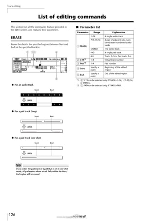
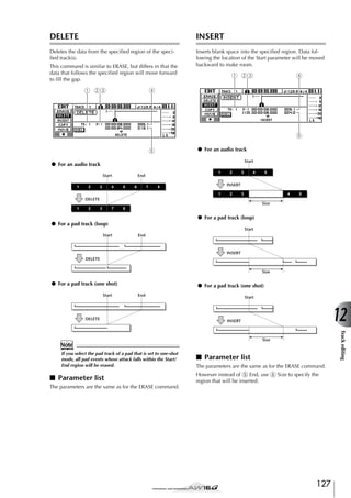

![*1.
2 From V.TR and 9 To V.TR can be selected only if
From TRACK=1–16, 1/2–15/16, or STEREO.
*2. 3 From PAD and J To PAD can be selected only if
TRACK=PAD.
*3. Measure lock function (6 Start Measure Lock, 7 End
Measure Lock)
“Measure lock” is a function that matches the beginning
of the measure or beat included in the copy-source
region with the desired location of the copy-destination.
To use the measure lock function, move the cursor to the
measure display field of From
Start or From End, specify the
measure/beat location that
will be the reference point for the matching, and press
the [ENTER] key. A “lock” icon will appear beside the
value that you specified, and the measure lock function
will be turned on for From Start or From End. (This can
be turned on for either Start or End, not both.)
While the measure lock function is on, the value of that
measure display format setting will be fixed, and cannot
be modified. In this state if you use the counter display
format field to specify the From Start and From End locations, and execute the copy, the location you specified in
the measure display format field will be aligned with the
copy-destination To Start setting.
MOVE
Moves the specified region of data to the specified location of the specified track. This is similar to COPY, but
differs in that the move-source data will be deleted.
1 23
8 9J
5
M
7
Start
End
From
Track
1
2
3
4
5
6
7
8
To
Track
A
B
C
D
E
F
G
H
To Start
Measure
MOVE
1
A
2
B
3
C
4
D
From
Track
End
5
E
To Start
6
F
7
G
1
2
3
4
5
6
7
8
To
Track
Start
To
Track
K
6
● For an audio track
● When measure lock = on
From
Track
4
A
B
4
5
6
F
G
H
8
H
● For a pad track (loop)
From Start
COPY
From
Track
1
2
3
4
5
6
7
8
From
PAD
To
Track
A
4
5
6
E
F
G
H
From End
To
PAD
To Start
To Start
12
To
PAD
● For a pad track (one shot)
From Start
Track editing
*4. The possible choices for 8 To TRACK (copy-destination
track) will depend on your selection for 1 From TRACK
(copy-source track).
If 1 From TRACK is a single audio track 1–16, you will be
able to select only a single audio track 1–16.
If 1 From TRACK is CLIP, STEREO, 1/2–15/16 (a pair of
adjacent audio tracks), you will be able to select only STEREO or 1/2–15/16 (a pair of adjacent audio tracks).
If 1 From TRACK is PAD, you will be able to select only
PAD.
If 1 From TRACK is ALL (OVER) or ALL (INS), you cannot
select TO TRACK.
*5. Grid function (M GRID)
When this function is on, the To Start location cannot be
specified in counter-display format; it can be specified
only in measure/beat units.
By using the Grid function in conjunction with the Measure Lock function, you can easily copy measure/beatlength segments of data whose divisions do not fall precisely on the measure or beat.
MOVE
From
PAD
From End
From
PAD
To
PAD
To Start
MOVE
From
PAD
To
PAD
■ Parameter list
The parameters are the same as for the COPY command.
However, you cannot select CLIP for 1 From TRACK.
Also, there is no L To Times setting.
129](https://image.slidesharecdn.com/aw16ge-131126034127-phpapp02/85/Aw16-ge-129-320.jpg)


![Track editing
Exporting WAV files and importing audio CD
or WAV files
This section explains how data from an AW16G audio
track or from a sample assigned to a pad can be written
(exported) to external media as a WAV file, and how a
WAV file or CD audio data from external media can be
loaded (imported) into an AW16G audio track.
Exporting WAV files
Any audio track of the AW16G or all sample data from
memory can be written as one or more WAV files onto
CD-R/RW media inserted in the CD-RW drive. This is
convenient when you want to send audio data to your
computer, or use waveform editing software to edit it.
Parameter
3
5
File Name*1
Virtual track number
Specify a
point
Beginning of the audio track
region that will be written
Specify a
point
End of the audio track region
that will be written
Up to eight
Displays the name of the file
alphanuto which the data will be writmeric charac- ten
ters
*1. The name of the individual source track (or odd-numbered track in the case of a pair) will be assigned by
default.
Repeatedly press the [EDIT] key or hold down
the [EDIT] key and use the CURSOR [ ]/[ ]
keys to access the EXPORT page.
4
Move the cursor to the From TRACK field,
and select the source data (audio track or
sample) that you want to write.
If you select “Tr1-16,” the current tracks of tracks 1–
16 will be written as separate monaural WAV files.
If you select “1–16,” the single specified track will
be written as a monaural WAV file.
If you select “1/2–15/16” or STEREO, the specified
pair of tracks (or the STEREO track) will be written
as a stereo WAV file.
If you select “SMPL,” all samples in memory will be
written as individual stereo WAV files.
This page shows the following information.
3 4
5
5
All samples in memory
From V.TR
The EDIT screen will appear.
2
The current track of tracks 1–
16
1–8
• In order to write WAV files, you must use CD-R/RW
media to which no data has been written.
• You cannot add data to CD-RW media that already contains data. You must first erase the CD-RW media.
• You cannot write a single WAV file that is larger than
the capacity of the media.
1
The stereo track
SMPL
2
From End
3
STEREO
Tr1-16
From
TRACK
4
In the Work Navigate section, press the
[EDIT] key.
A pair of adjacent odd-numbered/even-numbered audio
tracks
1
Note
1
2
Explanation
A single audio track
1/2–15/16
From Start
Insert CD-R/RW media into the CD-RW drive.
Range
1–16
If you selected 1–16, 1/2–15/16, or STEREO
as the source for exporting, move the cursor
to the From V.TR, From Start, and From End
fields, and specify the virtual track number
and region that will be exported.
Note
If you selected Tr1-16 as the export-source, the current
tracks for all sixteen tracks will be written automatically.
It is not possible to specify the virtual track number for
each.
132](https://image.slidesharecdn.com/aw16ge-131126034127-phpapp02/85/Aw16-ge-132-320.jpg)
![6
If necessary, move the cursor to the NAME
field, press the [ENTER] key, and input a file
name in the TITLE EDIT popup window.
For details on how to input a name, refer to page
24.
Note
• If you selected Tr1-16 as the export-source, the first six
characters of the song name + track number + “.WAV”
will automatically become the file name. This name
cannot be changed.
• In the file name you can use only uppercase alphabetical characters, numerals, and “_” (underscore). Lowercase alphabetical characters used in a song name will
be converted to uppercase characters, and all symbols
other than alphabetical characters and numerals will be
converted to “_”.
• If you selected SMPL as the export-source, the filename
will automatically be “SMPL” + pad number + “_” +
bank number + “.WAV.” This name cannot be changed.
7
Importing from an audio CD or
WAV file
CD audio data (CD-DA) or a WAV file from a CD-ROM
or CD-R can be imported (loaded) into an AW16G audio
track. After being imported, this data can be handled in
the same way as any recorded audio track.
1
If you want to import from an audio CD,
repeatedly press the Work Navigate section
[UTILITY] key or hold down the [UTILITY] key
and use the CURSOR [ ]/[ ] keys to access
the D.IN • HDD page of the UTILITY screen.
Immediately after the AW16G is powered-on, it will
be set to prohibit digital recording from an external
source or importing from a CD. Before you can
import, you will need to disable this prohibition in
the D.IN - HDD page of the UTILITY screen.
When you have finished setting the parameters, move the cursor to the EXEC button and
press the [ENTER] key.
A popup window with “Execute EXPORT?” will
appear, asking you to confirm the operation.
2
8
Move the cursor to the DIGITAL REC button,
and press the [ENTER] key.
3
Carefully read “Copyright Notice” (→ p. 5),
and if you accept these terms, move the cursor to the OK button and press the [ENTER]
key.
To execute the export, move the cursor to
the OK button and press the [ENTER] key.
Exporting will begin. If you move the cursor to the
CANCEL button (instead of the OK button) and
press the [ENTER] key, the export operation will be
cancelled. (However, it is not possible to abort the
export process once it has been started.)
Only if you selected “Tr1-16” as the export-source,
the maximum of sixteen WAV files can be distributed between multiple volumes of media as they
are exported. (Even in this case, it is not possible to
write a single WAV file that is larger than the capacity of the media.) When the “Exchange Next Media”
popup window appears, exchange the media and
press the [ENTER] key.
The button display will change from OFF to ON,
and digital recording and importing from a CD will
be enabled.
Note
The DIGITAL REC button will return to the OFF setting
each time you turn on the power.
• All WAV files will be written to the root directory.
• Since the AW16G does not have a concept of the realworld date and time, dummy values will be written as
the file creation date and time of the WAV files.
Note
• If CD-R/RW media that contains no data is inserted,
WAV file export will begin.
• If CD-RW media that contains data is inserted, a message of “Erase CD-RW media?” will appear, suggesting
that you erase the media. Move the cursor to the OK
button and press the [ENTER] key to erase the media, or
exchange the media.
• If media other than the above is inserted, it will automatically be ejected, and a message of “Change Media,
Please.” will appear. If this message appears, exchange
the media.
• Tracks that do not contain data in the specified region
will not be exported.
133
12
Track editing
Tip!
A message will ask you to confirm that you will
observe the applicable copyright laws.](https://image.slidesharecdn.com/aw16ge-131126034127-phpapp02/85/Aw16-ge-133-320.jpg)
![Track editing
4
Insert a CD into the CD-RW drive.
● When importing from audio CD/CD-Extra
You can import data from the following types of
media.
1
2
3
4
● Audio data (CD-DA)
• Audio CD
• CD-Extra (only the first session of CD-DA)
• Mixed Mode CD (only CD-DA data of the second and later tracks)
● WAV files
• ISO9660 Level 1 format CD-ROM, CD-R, CDRW*
• Mixed Mode CD
*The directory name and file name cannot use characters other than uppercase alphanumeric characters and the “_” (underscore) character. If you use
the AW16G to export WAV files onto CD-R/RW
media, the data will be in ISO9660 Level 1 format,
but please be aware of this restriction if you use a
computer to create WAV files.
5
In the Work Navigate section, repeatedly
press the [TRACK] key or hold down the
[TRACK] key and use the CURSOR [ ]/[ ]
keys to access the CD IMPORT page.
The READ CD INFO button will appear in the center of the display.
5 6
7
1 From CD TRACK
Specifies the audio track number (01–99) of the
import-source CD.
B From Start
Specifies the beginning of the data that will be
imported, in minutes/seconds/frames (1/75 second).
C From End
Specifies the end of the data that will be imported,
in minutes/seconds/frames (1/75 second).
Tip!
The “frames” referred to here are the minimum time-axis
units used in CD-DA. Do not confuse them with the
frames used in MTC or SMPTE.
D LISTEN button
You can move the cursor to this button and press
the [ENTER] key to repeatedly hear the currently
selected region of the CD-DA.
E To TRACK
6
Press the [ENTER] key.
The display will indicate “Read CD Info...,” and
information will be read from the CD inserted in the
CD-RW drive.
Depending on the import-source data, the screen
will change as follows.
Selects the track number into which the data will be
imported. If the import-source is an audio CD or a
stereo WAV file, you will only be able to select a
pair of tracks 1/2–15/16.
F To V.TR
Selects the virtual track number (1–8) into which
the data will be imported.
G To Start
Specifies the starting location (in counter-display
format) of the import-destination to which the data
will be imported.
134](https://image.slidesharecdn.com/aw16ge-131126034127-phpapp02/85/Aw16-ge-134-320.jpg)
![● When importing a WAV file
2
1
3
4
7
If you are importing a WAV file, move the
cursor to the From WAVE file field, and turn
the [DATA/JOG] dial to select the WAV file
that you want to import.
To move to a lower level, display the
icon in this
field, then move the cursor to the ENTER button in
the screen and press the [ENTER] key.
To move to the next higher level, display the
icon in this area, then move the cursor to the UP
button and press the [ENTER] key.
5
6
7
1 From WAVE file
Selects the WAV file that will be imported.
If the media contains folders (directories), move to
the folder that contains the WAV file you want to
import, and then specify the desired WAV file.
The icons shown here have the following meaning.
............................. Indicates that a WAV file is
selected.
............................. Indicates that a folder in the same
level is selected.
............................. Indicates that the folder in the next
higher level is selected.
B Mono/stereo
Indicates whether the WAV file selected for importing is monaural (M) or stereo (S). This field is for display only, and cannot be changed.
8
9
If you are importing from audio CD or CDExtra, use the From Start and From End fields
to specify the region that will be imported.
Use the To TRACK, To V.TR, and To Start
fields to specify the track number, virtual
track number, and starting location into
which the data will be imported.
Note
If the import-destination already contains data, it will be
overwritten. Be careful not to accidentally overwrite
important data.
10
When you have finished making settings,
move the cursor to the EXEC button and
press the [ENTER] key.
A popup window will ask you to confirm the operation.
C Size
Indicates the playback length (in msec) of the WAV
file selected for importing. This field is for display
only, and cannot be changed.
D LISTEN/ENTER/UP button
The name and function of the button displayed here
will change depending on the item that is selected
by the From WAVE file parameter.
● If a WAV file ( ) is selected
The LISTEN button will be displayed, allowing you
to hear the WAV file repeatedly.
● If the next higher folder ( ) is selected
The UP button will be displayed, allowing you to
move to the next higher folder.
E To TRACK
F To V.TR
G To Start
To execute the import operation, move the
cursor to the OK button and press the
[ENTER] key.
Importing will begin. If you move the cursor to the
CANCEL button and press the [ENTER] key, importing will be cancelled.
Tip!
Even after you press the [ENTER] key, you can press the
[UNDO/REDO] key to return to the state prior to
importing, as long as you have not executed any editing
or recording operation since the import.
Note
You cannot execute the Import operation while the
AW16G is running.
These fields are the same as when you are importing from audio CD or CD-Extra.
Note
• If a Mixed Mode CD is inserted in the CD-RW drive, a
popup window will appear, allowing you to select
AUDIO (CD-DA) or WAVE (WAV files) to import. Move
the cursor to the button for the data that you want to
import, and press the [ENTER] key.
• You can import only monaural or stereo WAV files that
are in 16-bit/44.1 kHz format.
• When you move the cursor to the LISTEN button and
press the [ENTER] key, there will be a slight time lag
while the data is read from the CD before you hear it.
135
12
Track editing
● If a folder in the same level ( ) is selected
The ENTER button will be displayed, allowing you
to move into that folder.
11](https://image.slidesharecdn.com/aw16ge-131126034127-phpapp02/85/Aw16-ge-135-320.jpg)


![Song management
Editing the song name
Here’s how to edit the song name that is assigned when
you create a new song.
Note
• This setting applies only to the current song. Before you
perform this procedure, load the song whose name you
want to edit.
• The edited name will be saved with the song data when
you save the song.
1
In the Work Navigate section, press the
[SONG] key.
2
Repeatedly press the [SONG] key or hold
down the [SONG] key and use the CURSOR
[ ]/[ ] keys to access the SETUP page.
3
To edit the song name, move the cursor to
the NAME button and press the [ENTER] key.
4
Input the new name. Then move the cursor
to the OK button and press the [ENTER] key.
138
The SONG screen will appear.
The TITLE EDIT popup window will appear, allowing you to edit the song name.
The new name will be applied, and the popup window will close. (For details on inputting a name →
p. 24)](https://image.slidesharecdn.com/aw16ge-131126034127-phpapp02/85/Aw16-ge-138-320.jpg)
![Editing various settings for the song
Here’s how to make various settings for a song, such as
switching protect on/off and selecting the counter display
format and time code format.
4
Note
In the COUNTER DISPLAY area, use the following
buttons to select the display format for the counter
that is shown in the center of the top line in the display.
• These settings apply only to the current song. Before
you perform this procedure, load the song whose settings you want to edit.
• The edited settings will be saved with the song data
when you save the song.
1
ABS (absolute time) ....Display the current location in
hours/minutes/seconds/milliseconds, with the absolute time zero
location as 0.
REL (relative time) ......Display the current location in
hours/minutes/seconds/milliseconds, with the relative time zero
location as 0.
SEC .............................Display the current location in
hours/minutes/seconds/milliseconds, with the Start point as 0.
T.C..............................Display the current location in
time code (hours/minutes/seconds/
frames), with the Start point as 0.
REMAIN .....................When this button is on, the
remaining recordable time with
the selected number of recording
tracks will be displayed instead of
the current location.
In the Work Navigate section, press the
[SONG] key.
2
Repeatedly press the [SONG] key or hold
down the [SONG] key and use the CURSOR
[ ]/[ ] keys to access the SETUP page.
The SONG screen will appear.
1
3
2
Note
• The counter in the upper right of the display always
shows the current location in measure/beat units, relative to the Start point.
• The measure/beat display will depend on the settings in
the TEMPO page of the SONG screen. For details, refer
to “Creating a tempo map” (→ p. 142).
This page contains the following items.
1 PROTECT button
Switches protect on/off.
B COUNTER DISPLAY
Selects the display format for the counter that
appears in the center of the top line in the display.
C TIME CODE BASE
Selects the format (the number of frames per second) for the time code used by the AW16G.
3
To switch the protect setting on/off, move
the cursor to the PROTECT button and press
the [ENTER] key.
Tip!
• We recommend that you turn protect on for important
songs.
• Even if protect is on, you can still copy the song (→
p. 140) and adjust the mixer settings.
5
To change the time code frame rate, move
the cursor to one of the buttons in the TIME
CODE BASE area, and press the [ENTER] key.
In the TIME CODE BASE area you can choose one
of the following frame rates to specify the minimum
unit of time code.
24 ...............................24 frames/second
25 ...............................25 frames/second
30 ...............................30 frames/second (30 non-drop
frame)
30D ............................29.97 frames/second (30 dropframe)
Tip!
This setting affects both the counter time code display
and the MTC that the AW16G transmits and receives. If
the AW16G is sending or receiving MTC to or from an
external device, you must set both devices to the same
frame rate.
Note
With the exception of COUNTER DISPLAY, the settings in
the SETUP page of the SONG screen cannot be changed
while the AW16G is running.
139
13
Song management
Protect is a setting that prohibits any change to the
song data. If protect is turned on, the PROTECT button will be highlighted, and it will not be possible
to perform additional recording or editing, or to
erase the song.
To change the counter display format, move
the cursor to one of the buttons in the
COUNTER DISPLAY area and press the
[ENTER] key.](https://image.slidesharecdn.com/aw16ge-131126034127-phpapp02/85/Aw16-ge-139-320.jpg)
![Song management
Copying or deleting a song
Here’s how to copy or delete a song in the hard disk.
Note
• You cannot copy or delete a song while the AW16G is
running.
• A deleted song will be lost forever. Use great caution
when deleting a song.
• You cannot delete a song for which protect is on, or
delete the current song (the highlighted song). If you
want to delete such a song, you must first turn off the
protect setting or switch the current song.
1
Repeatedly press the [SONG] key or hold
down the [SONG] key and use the CURSOR
[ ]/[ ] keys to access the LIST page.
4
In the Work Navigate section, press the
[SONG] key
2
■ To copy a song
Move the cursor to the COPY button and
press the [ENTER] key.
A popup window will ask you to confirm the copy
operation.
Tip!
If you have selected the current song as the song to be
copied, a popup window will ask you whether you want
to save the current song. Move the cursor to either the
YES button (if you want to save) or the NO button (if you
don’t want to save), and then press the [ENTER] key.
The SONG screen will appear.
5
To execute the copy, move the cursor to the
OK button and press the [ENTER] key.
The song you selected in step 3 will be copied, and
you will return to step 2. If you move the cursor to
the CANCEL button and press the [ENTER] key, the
copy operation will be cancelled.
Note
1 2
When you copy a song, the hard disk will contain two
songs with the identical song name and size. To avoid
confusion, we recommend that you rename the song
after copying it.
This page contains the following items.
1 DELETE button
Displays a popup window that allows you to delete
a song.
■ To delete a song
Displays a popup window that allows you to copy a
song.
3
6
Following step 3, move the cursor to the
DELETE button and press the [ENTER] key.
7
B COPY button
To delete the song, move the cursor to the
OK button and press the [ENTER] key.
Turn the [DATA/JOG] dial to select the song
that you want to copy or delete.
A popup window will ask you to confirm the delete
operation.
The line that is enclosed by a dotted frame indicates
the selected song.
The song you selected in step 3 will be deleted, and
you will return to step 2. If you move the cursor to
the CANCEL button and press the [ENTER] key, the
delete operation will be cancelled.
Note
If you have selected the current song as the song to be
deleted, a popup window will warn you that it is not possible to delete the current song.
140](https://image.slidesharecdn.com/aw16ge-131126034127-phpapp02/85/Aw16-ge-140-320.jpg)
![Optimizing a song
“Optimize” is an operation that deletes the undo/redo
audio data maintained within the song. When you have
finished recording and editing a song, you can execute
the Optimize operation on that song to increase the
amount of free space on the hard disk.
Note
The deleted undo/redo audio data will be lost forever.
Use this operation with caution.
1
In the Work Navigate section, repeatedly
press the [SONG] key or hold down the
[SONG] key and use the CURSOR [ ]/[ ]
keys to access the LIST page of the SONG
screen.
2
Turn the [DATA/JOG] dial to select the song
that you want to optimize.
3
Move the cursor to the OPTIMZ button, and
press the [ENTER] key.
The line enclosed by the dotted frame indicates the
selected song.
A popup window will ask you to confirm the optimize operation.
Tip!
You may select the current song to be optimized. In this
case, a popup window will ask you whether you want to
save the current song. Move the cursor to the YES button
(if you want to save) or the NO button (if you don’t want
to save), and press the [ENTER] key.
4
13
Song management
To execute the optimize operation, move the
cursor to the OK button and press the
[ENTER] key.
The undo/redo audio data of the song you selected
in step 2 will be deleted, and you will return to step
1. If you decide not to execute the optimize operation, move the cursor to the CANCEL button and
press the [ENTER] key.
141](https://image.slidesharecdn.com/aw16ge-131126034127-phpapp02/85/Aw16-ge-141-320.jpg)
![Song management
Creating a tempo map
The “tempo map” contains data to change the tempo or
time signature at the beginning of the song or at any
measure or beat within the song. The measure/beat display counter, the Quick Loop Sampler, the internal metronome, and the MIDI clock data generated within the
AW16G are all based on this tempo map.
2
Repeatedly press the [SONG] key or hold
down the [SONG] key and use the CURSOR
[ ]/[ ] keys to access the TEMPO page.
In this page you can input or edit tempo map events
for the current song.
2 67
The AW16G’s tempo map can also record data to switch
scenes (→ p. 73) or Pad sample banks (→ p. 107). You
can use this to switch scenes as the song progresses, or to
switch the sounds that are played by the Quick Loop
Sampler.
8
9
J
K
Tip!
• The Start point of the song corresponds to the starting
location of the tempo map.
• The data (“tempo map events”) recorded in the tempo
map will continue to apply until the location at which
the next event of the same type has been input.
Note
If you modify the tempo map after recording on an audio
track, the measure/beat counter display values will be
affected. For this reason if you want to use MIDI clock to
synchronize with an external MIDI device, or if you want
to control the song in measure units, you should create
the tempo map before you record. If you modify the
tempo map after a track has already been recorded, a
popup window will ask you for confirmation.
34 5
This page contains the following items.
1 List
This area lists the tempo map events that have been
input for the current song. The line enclosed by a
dotted frame is the currently selected tempo map
event.
B LOCATE button
By moving the cursor to this button and pressing the
[ENTER] key, you can move the song to the location
of the tempo map event currently selected in the
list.
■ Editing a tempo map event
When you create a new song, the following tempo map
event will be input at the beginning of the tempo map
(the first beat of the first measure).
• Time signature: 4/4
• Tempo: 120.0
• Pad sample bank: Pad 1=A, Pad 2=A,
Pad 3=A, Pad 4=A
• Scene number: not assigned
Here’s how to edit the values of this tempo map event.
1
In the Work Navigate section, press the
[SONG] key.
1
C DELETE button
To delete the tempo map event currently selected in
the list, move the cursor to this button and press the
[ENTER] key.
D INSERT button
To insert a blank event at the step preceding the
tempo map event currently selected in the list,
move the cursor to this button and press the
[ENTER] key.
E NEW button
To create an event at the beginning of the measure
following the last step, move the cursor to this button and press the [ENTER] key.
The SONG screen will appear.
F STEP
Indicates the step number of the tempo map event.
G MEAS
Indicates the location (measure/beat) at which the
tempo map event is input.
H
I
J
K
METER
TEMPO
PAD BANK 1–4
SCENE
These fields show the time signature, tempo, pad
sample bank, and scene number of each tempo
map event.
142](https://image.slidesharecdn.com/aw16ge-131126034127-phpapp02/85/Aw16-ge-142-320.jpg)
![3
Move the cursor to the item that you want to
edit, and turn the [DATA/JOG] dial to edit the
value.
If the METER, TEMPO, PAD BANK 1–4, or SCENE
value is “–”, move the cursor to the item and press
the [ENTER] key before you edit the value.
■ Adding a tempo map event
1
If you use the INSERT button instead of the NEW button,
a blank tempo map event will be inserted before the currently selected step. However, you cannot insert an event
before the tempo map event at the beginning of the song
(i.e., the tempo map event that is input when you create
the song).
• The METER, TEMPO, and PAD BANK 1–4 at the beginning of the song cannot be set to “–”.
• You cannot change the METER value to other than “–”
for a step that is not located at beat 1.
The range for each item is as follows.
METER
TEMPO
PAD BANK
1–4
SCENE
A blank tempo map event will be created after the
last step that is currently input.
Tip!
Note
Event
Access the TEMPO page, move the cursor to
the NEW button, and press the [ENTER] key.
Range
Content
1/4 to 8/4, –
Specifies the time signature of
the song.
30.0 to
250.0, –
Specifies the tempo of the
song. You can set the tempo
in units of 0.1 over a range of
30.0–250.0 BPM.
A to D, –
Selects the sample bank that
will be used for each pad 1–4.
00 to 96, –
2
Switches the scene number
used by the song.
When the cursor is located outside the list, you can
turn the [DATA/JOG] dial to scroll the contents of
the list.
3
Move the cursor to the MEAS field of the
event that is selected in the list, and turn the
[DATA/JOG] dial to specify the location of the
event.
You can adjust the location of a tempo map event in
units of measures or beats. However, you cannot
move an event past the preceding or following
event.
Tip!
• You cannot delete the tempo map event located at the
beginning of the song, or change its location. If you
want to change the tempo or time signature during the
song, you can insert a new event.
• If you set METER, TEMPO, PAD BANK 1–4, or SCENE
to a value of “–”, that event will be disabled. For example if you want to specify only the time signature and
tempo, you should set the pad bank and scene to “–”.
Make sure that the cursor is outside the list,
and turn the [DATA/JOG] dial to select a
tempo map event that you created.
4
Move the cursor to the item that you want to
edit, and turn the [DATA/JOG] dial to adjust
the value.
If necessary, you can play back the song to check
that the tempo map event works as you expect.
5
In the same way, use the NEW or INSERT button to add new events, and set their parameters.
■ Deleting a tempo map event
Here’s how to delete an unwanted event from the tempo
map. (However, you cannot delete the event that is
located at the beginning of the song.)
Access the TEMPO page, and scroll the list to
select the tempo map event that you want to
delete.
Move the cursor to the DELETE button and
press the [ENTER] key.
The selected event will be deleted.
143
13
Song management
1
2](https://image.slidesharecdn.com/aw16ge-131126034127-phpapp02/85/Aw16-ge-143-320.jpg)
![Song management
Importing data from an existing song
Here’s how selected items of data such as scenes, libraries, or individual tracks of audio data from a song saved
on the hard disk can be imported into the current song.
Note
When you execute this import operation, the previous
data (for that item) in the current song will be lost. Use
this procedure with caution.
■ Importing library/scene/tempo map
data
1
Move the cursor to either the LIBRARY,
SCENE, or TEMPO MAP button, and press
the [ENTER] key.
A popup window will ask you to confirm the import
operation.
■ Selecting the song from which you
will import data
1
In the Work Navigate section, press the
[SONG] key.
2
Repeatedly press the [SONG] key or hold
down the [SONG] key and use the CURSOR
[ ]/[ ] keys to access the IMPORT page.
The SONG screen will appear.
1
2
2
To execute the import, move the cursor to
the OK button and press the [ENTER] key.
Importing will begin. When the data has been
imported, you will return to the screen of step 2.
■ Importing a specific track
1
Move the cursor to the TRACK button and
press the [ENTER] key.
A popup window will ask you to select the track to
be imported.
1
3
4
2
3
This page contains the following items.
1 LIBRARY button
Imports all libraries into the current song.
B SCENE button
1 TRACK
Specify the import-source track number.
Imports all scenes into the current song.
C TRACK button
Imports the audio data of a single track into the current song.
B V.TR
Specify the import-source virtual track number.
C NAME
Displays the name of the currently selected virtual
track.
D TEMPO MAP button
Imports the tempo map into the current song.
3
Turn the [DATA/JOG] dial to select the song
from which you want to import data.
The line enclosed by the dotted frame is the song
you have selected as the import-source.
2
Move the cursor to the TRACK field and V.TR
field, and turn the [DATA/JOG] dial to specify
the track number and virtual track number.
The name of the selected import-source track will
be displayed in the NAME field.
Note
You can import only one track at a time.
144](https://image.slidesharecdn.com/aw16ge-131126034127-phpapp02/85/Aw16-ge-144-320.jpg)
![3
A popup window will ask you to select the importdestination track.
1
4
Move the cursor to the TRACK field and V.TR
field, and turn the [DATA/JOG] dial to specify
the track number and virtual track number
for the import-destination.
5
Move the cursor to the OK button and press
the [ENTER] key.
To execute the import, move the cursor to
the OK button and press the [ENTER] key.
Importing will begin. When the track has been
imported, you will return to the state of step 2.
2
3
1 TRACK
Specify the import-destination track number.
B V.TR
Specify the import-destination virtual track number.
C NAME
Displays the name of the virtual track that you
selected as the import-destination.
Backing up songs and sample libraries
Here’s how you can back up songs or sample libraries
from the internal hard disk to CD-R/RW media.
1
2
3
Insert CD-R/RW media into the CD-RW drive.
In the Work Navigate section, press the [CD]
key.
The CD screen will appear.
Repeatedly press the [CD] key or hold down
the [CD] key and use the CURSOR [ ]/[ ]
keys to access the BACKUP page.
In this page you can back up songs or sample libraries from the internal hard disk to CD-R/RW media.
3
2
1
This page contains the following items.
1 List
This area lists the songs or sample libraries that are
saved on the hard disk. The symbols at the right of
the list indicate whether an item of data has been
selected (●) or disabled (O) for backup.
B PAD button
When this button is off, the list will show the songs
that are saved on the hard disk. When this button is
on, the list will show the sample libraries that are
saved on the hard disk.
C ALL button
If you turn this button on and then turn the ENABLE/
DISABLE button on, all data displayed in the list
will be selected for backup.
D ENABLE/DISABLE button
Selects whether an item of data will be selected for
backup (ENABLE) or not selected (DISABLE).
5 6
4
Backs up the audio tracks within a song in the format of an AW2816 backup file.
If you turn this button on, you will be able to back
up only one song at a time. The data selection symbol (●) will apply only to the selected song, and the
ALL button and ENABLE/DISABLE button will be
unavailable.
F EXECUTE button
Executes the backup operation for the selected
song(s) or sample library(ies).
145
Song management
E AS AW2816 button
13](https://image.slidesharecdn.com/aw16ge-131126034127-phpapp02/85/Aw16-ge-145-320.jpg)
![Song management
4
Turn the [DATA/JOG] dial to select the song
or sample library data that you want to back
up. Then move the cursor to the ENABLE/
DISABLE button and press the [ENTER] key.
The symbol for the selected data will change to the
● symbol, indicating that this data has been
selected for backup. You can repeat this step to
select multiple items of data for backup.
If you turn on the ALL button and then move the
cursor to the ENABLE/DISABLE button and press the
[ENTER] key, you can select all data in the list in
one step.
Tip!
If you turn on the NAME or OLD button, the data in the
list will be sorted alphabetically or by the order in which
it was saved.
5
To execute the backup, move the cursor to
the EXECUTE button and press the [ENTER]
key.
A popup window will ask you to confirm the operation.
Note
• If previously-recorded CD-RW media is inserted in the
CD-RW drive, a popup window will ask you if it is OK
to erase the media first. Move the cursor to the OK button and press the [ENTER] key, and the media will be
erased.
• If a CD-ROM or previously-recorded CD-R media is
inserted in the CD-RW drive, a popup window with a
message of “Change Media, Please” will appear, and
the media will be ejected. Remove the media, and
replace it with writable media.
146
6
Move the cursor to the OK button and press
the [ENTER] key.
Writing to the CD-R/RW media will begin. If you
decide to cancel the backup operation, move the
cursor to the CANCEL button and press the [ENTER]
key.
While the backup operation is being executed, a
popup window will indicate the progress. When the
backup has been completed, you will return to step
3.
If the backup data does not fit on a single volume of
media, a message of “Note Label, Exchange Next”
will appear, and the media will be ejected. Insert a
new volume of media. Then move the cursor to the
OK button and press the [ENTER] key.
Note
• You cannot execute the backup operation without
selecting data.
• If you execute the backup operation with the AS
AW2816 button turned off, system data (the settings
you make in the UTILITY screen) will be backed up on
the media together with the selected data.
• If you execute the backup operation with the AS
AW2816 button turned on, data other than audio tracks
will not be backed up. All virtual tracks for tracks 1–16
will be backed up. For the stereo track, only the current
track will be backed up.
• When you restore data that was backed up to more
than one volume of media, you must insert the media in
the order in which it was backed up. Be sure to make a
note of the backup sequence on the label surface of
each CD-R/RW media.](https://image.slidesharecdn.com/aw16ge-131126034127-phpapp02/85/Aw16-ge-146-320.jpg)
![Restoring songs or sample libraries
Here’s how data that you backed up to CD-R/RW media
can be restored to the hard disk of the AW16G.
1
Insert the CD-R/RW media containing the
backup data into the CD-RW drive.
2
You cannot operate the items in the RESTORE page until
the inserted CD-R/RW media has been read.
In the Work Navigate section, press the [CD]
key.
3
Note
Repeatedly press the [CD] key or hold down
the [CD] key and use the CURSOR [ ]/[ ]
keys to access the RESTORE page.
If the backup data occupies more than one volume
of media, insert the first volume.
Make sure that the cursor is located at the
READ CD INFO button, and press the
[ENTER] key.
Information will be read from the inserted CD-R/
RW media. When the information has been read, a
display like the following will appear.
3
2
1
Turn the [DATA/JOG] dial to select the data
that you want to restore. Then move the cursor to the ENABLE/DISABLE button and press
the [ENTER] key.
The symbol at the right will change to the ● symbol, indicating that this data has been selected for
restoring.
If you turn on the ALL button and then move the
cursor to the ENABLE/DISABLE button and press the
[ENTER] key, all data shown in the list will be
selected in one step.
The CD screen will appear.
In this page, data that you backed up to CD-R/RW
media can be restored to the internal hard disk.
4
5
6
If you want to restore the system data, move
the cursor to the SYSTEM button and press
the [ENTER] key.
The button will be turned on, and the system data
will be selected for restoring.
7
To execute the restore operation, move the
cursor to the EXECUTE button and press the
[ENTER] key.
A popup window will ask you to confirm the operation.
6
54
1 List
This area lists the data that has been backed up on
the CD-R/RW media. The symbols at the right of the
list indicate whether an item of data has been
selected (●) or disabled (O) for restore.
B PAD button
C ALL button
You can use this button to select all the data that
appears in the list. If you turn this button on and
then turn the ENABLE/DISABLE button on, all data
displayed in the list will be selected for restore.
Move the cursor to the OK button if you
want to execute the restore operation (or to
the CANCEL button if you decide not to
restore), and press the [ENTER] key.
The current song will be saved automatically, and
the restore operation will begin.
A popup window will indicate the progress of the
restore operation. When the operation is finished,
you will return to step 3.
If the backup occupied more than one volume of
CD-R/RW media, a message of “Exchange Next
Media #XXX” (where XXX is a number) will be displayed during the restore process. Exchange the
CD-R/RW media for the media of the corresponding
number. Then move the cursor to the OK button and
press the [ENTER] key.
D ENABLE/DISABLE button
Selects whether an item of data will be selected for
restore (ENABLE) or not selected (DISABLE).
E SYSTEM button
Selects the system data (AW16G settings you make
in the UTILITY screen) for restoring.
F EXECUTE button
Executes the restore operation
147
13
Song management
When this button is off, the list will show the songs
that were backed up on the CD-R/RW media. When
this button is on, the list will show the sample
libraries that were backed up on the CD-R/RW
media.
8](https://image.slidesharecdn.com/aw16ge-131126034127-phpapp02/85/Aw16-ge-147-320.jpg)
![Song management
Exchanging song data with the
AW4416/AW2816
You can back up an AW16G song in a format that is
compatible with the AW4416/AW2816. Conversely, a
song that was backed up by the AW4416/2816 can be
restored into the AW16G.
Note
Only the audio data recorded in a song can be exchanged
with the AW4416/2816. Mix parameters, libraries, and
system data cannot be backed-up/restored in this way.
■ Backing up an AW16G song in a format compatible with the AW4416/
AW2816
If you turn on the AS AW2816 button in the BACKUP
page of the CD screen, the data will be saved in the
AW2816 backup file format.
■ Restoring AW4416/AW2816 songs
1
2
Insert CD-R/RW media containing the
AW4416/AW2816 song backup into the
AW16G.
3
4
Repeatedly press the [CD] key or hold down
the [CD] key and use the CURSOR [ ]/[ ]
keys to access the RESTORE page.
In the Work Navigate section, press the [CD]
key.
The CD screen will appear.
Make sure that the cursor is located at the
READ CD INFO button, and press the
[ENTER] key.
Data will be read from the inserted CD-R/RW
media. When the data has been read, a screen like
the following will appear.
An AW2816 backup file can be restored into an AW2816
or an AW4416 (version 2.0 or later).
For the procedure, refer to “Backing up songs or sample
libraries,” earlier in this manual.
Note
• Backup in the AW2816 backup file format is limited to
one song at a time.
• When you perform a backup in the AW2816 backup file
format, data other than the audio tracks will not be
backed up. All virtual tracks of tracks 1–16 will be
backed up. For the stereo track, only the current track
will be backed up.
5
6
Turn the [DATA/JOG] dial to select a song
that you want to restore.
Move the cursor to the ENABLE/DISABLE button and press the [ENTER] key.
The symbol at the right of the data will change to ●,
and the data will be selected for restoring.
Note
The list will show all the songs that were backed up to
CD-R/RW media, but you can execute the restore operation only for 44.1 kHz/16-bit songs.
7
8
Repeat steps 5 and 6 to select all of the
AW4416/AW2816 songs that you want to
restore.
To execute the restore operation, move the
cursor to the EXECUTE button and press the
[ENTER] key.
The restore operation will begin. While the song
data is being loaded, a popup window will indicate
the progress.
148](https://image.slidesharecdn.com/aw16ge-131126034127-phpapp02/85/Aw16-ge-148-320.jpg)
![Chapter 14
MIDI and utility functions
This chapter explains basic MIDI-related settings, functions that use
MIDI, and various utility functions.
What you can do using MIDI
On the AW16G, you can use MIDI to do the following
things.
● Synchronize operation with an external device
You can synchronize an AW16G song with the playback of an external device (such as a MIDI
sequencer) by exchanging synchronization messages
such as MTC (MIDI Time Code) or MIDI Clock with
the external device.
● Remote control of the transport
You can transmit MMC (MIDI Machine Control) messages from a MIDI sequencer or other external MIDI
device to the AW16G to remotely control the
AW16G’s transport. Conversely, you can also transmit MMC from the AW16G to an external device to
control its transport.
Example of using MTC/MMC to synchronize the
operation of the AW16G and a MIDI sequencer
(computer)
MTC
MIDI OUT/THRU
connector
MIDI IN
MMC
MIDI IN connector
AW16G
Example of recording/playing scene selections and
mix parameter operations on a MIDI sequencer
(computer)
Control changes
Program changes
MIDI OUT/THRU
connector
MIDI IN connector
AW16G
MIDI IN
MIDI OUT
Control changes
Program changes
External MIDI device
(e.g., computer)
● Bulk dump
The AW16G’s internal settings such as library data
and scene memories can be transmitted as “bulk
data” and recorded on a MIDI sequencer or other
external MIDI device. The recorded bulk data can
then be transmitted to the AW16G to restore its internal settings to their previous state. This can also be
used to copy settings between two AW16G units.
Example of recording/playing bulk data on a MIDI
sequencer (computer)
Bulk data
MIDI OUT
MIDI OUT/THRU
connector
External MIDI device
(e.g., computer)
● Automate scene changes and mix parameter operations
When you recall a scene on the AW16G or operate
its mix parameters, the corresponding messages (program changes or control changes) can be transmitted
from the MIDI OUT/THRU connector to an external
device.
If you record these messages on a MIDI sequencer
that is synchronized to the AW16G song, these scene
recall operations or realtime mix parameter operations can be reproduced whenever you want.
MIDI IN
Bulk data
MIDI IN connector
AW16G
MIDI OUT
External MIDI device
(e.g., computer)
● MIDI Remote
“MIDI Remote” is a function that lets you use the
AW16G as a physical controller for an external
device. You can assign the desired MIDI messages to
the faders and [TRACK SEL] keys of the top panel,
and use them to remotely control a MIDI device or
computer program.
Example of using the AW16G as a physical controller for a MIDI sound module
Control changes
System exclusive
messages, etc.
MIDI OUT/THRU
connector
AW16G
MIDI IN
External MIDI device
(e.g., computer)
149](https://image.slidesharecdn.com/aw16ge-131126034127-phpapp02/85/Aw16-ge-149-320.jpg)
![MIDI and utility functions
Basic MIDI settings
In the MIDI page of the UTILITY screen, you can make
various MIDI-related settings such as selecting the MIDI
messages that will be output from the MIDI OUT/THRU
connector, and specifying MTC/MMC transmission and
reception.
To access this page, repeatedly press the Work Navigation section [UTILITY] key or hold down the [UTILITY]
key and use the CURSOR [ ]/[ ] keys.
1
2
4
SLAVE button..............If this button is on, the AW16G
will be the MTC slave, and will follow MMC commands that it
receives at the MIDI IN connector.
Use this setting when you want to
remotely control the transport of
the AW16G from an external MIDI
device.
Tip!
7
If you want to use the AW16G as the MMC master, make
sure that the MIDI button is turned on in the MIDI OUT
area.
C DEV (device number)
Specifies the MMC device number (1–127) that the
AW16G will receive.
Note
3
6
5
9 8
This page contains the following items.
1 MIDI OUT
Selects the type of MIDI messages that will be output from the MIDI OUT/THRU connector.
MIDI button............... If this button is on, various MIDI
messages generated within the
AW16G (except for MIDI Clock
and MTC) will be transmitted. If
you turn this button on, the THRU
button will be defeated.
CLK button................. If this button is on, MIDI Clock
(and Start, Stop, Continue, and
Song Position Pointer) messages
will be transmitted while the
recorder is running. If you turn this
button on, the MTC button will be
defeated.
MTC ........................... If this button is on, MTC (MIDI
Time Code) will be transmit while
the recorder is running. If you turn
this button on, the CLK button will
be defeated.
THRU button ............. If this button is on, MIDI messages
received at the MIDI IN connector
will be re-transmitted without
change from the MIDI OUT/THRU
connector, and none of the MIDI
messages generated within the
AW16G itself will be transmitted. If
you turn this button on, the MIDI/
CLK/MTC buttons will be defeated.
B MMC MODE
Specifies how MMC will be transmitted/received.
MASTER button.......... If this button is on, the AW16G
will be the MMC master. When
you operate the transport, the corresponding MMC command will
be transmitted from the MIDI
OUT/THRU connector. Use this
setting when you want to remotely
control an external MIDI device
from the AW16G.
150
• The MMC device number is an identifying number used
to distinguish devices that transmit and receive MMC
commands. When using MMC, the AW16G and the
external MIDI device must be set to the same MMC
device number.
• The MMC device number is displayed as a decimal
number starting from one. Some devices display the
MMC device number as a hexadecimal number starting
from zero. In this case, the numbers will correspond as
follows.
AW16W display → hexadecimal display
1 → 00h
127 → 7Eh
• The AW16G always transmits MMC commands using
the “All” device number (7Fh in hexadecimal).
D MTC MODE
Specifies how the AW16G operate when synchronized with an external MIDI device using MTC
(MIDI Time Code).
MASTER button ..........If this button is on, the AW16G
will be the MTC master. When you
operate the transport of the
AW16G, MTC will be transmitted
from the MIDI OUT/THRU connector. Use this setting if you want
to the external MIDI device to follow the AW16G, or if you are
using the AW16G by itself.
SLAVE button..............If this button is on, the AW16G
will be an MTC slave, and will follow MTC data it receives at the
MIDI IN connector. Use this setting
if you want to synchronize with a
second AW16G unit, or if you
want to synchronize the AW16G
with an external MIDI device that
can function only as the MTC master.
Tip!
When using the AW16G as the MTC master, make sure
that the MIDI button and MTC button in the MIDI OUT
area are both turned on.
E AVRG (Average)
Select one of the following to specify how closely
the AW16G will follow the incoming MTC data
when functioning as an MTC slave.](https://image.slidesharecdn.com/aw16ge-131126034127-phpapp02/85/Aw16-ge-150-320.jpg)


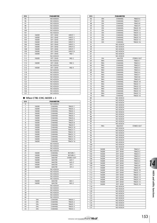
![MIDI and utility functions
Transmitting the AW16G’s settings via MIDI
(Bulk Dump)
In the BULK page of the UTILITY screen, you can transmit various internal settings of the AW16G (scene memories, libraries, settings of the UTILITY screen, etc.) as bulk
data from the MIDI OUT/THRU connector. If you record
this bulk data on a MIDI sequencer or similar device,
you will then be able to restore these settings whenever
desired.
To access this page, repeatedly press the [UTILITY] key
or hold down the [UTILITY] key and use the CURSOR
[ ]/[ ] keys.
1
2
9
I RX DISABLE button
Selects whether bulk data sent from an external
device will be received (button = on) or ignored
(button = off).
J REQUEST button
When you move the cursor to this button and press
the [ENTER] key, a bulk dump request message will
be transmitted from the MIDI OUT/THRU connector.
A bulk dump request message is a MIDI message
that requests an AW16G to transmit the settings you
selected in items 1–7.
When two AW16G units are connected, you can
use this to copy data such as scene memories or
libraries from the other AW16G.
● Bulk dump request message transmission
AW16G
34
7
5
6
8
K J
This page contains the following items.
1 SCENE button
Selects scene memories for bulk dumping. Use the
scene number field located at the right of the button
to specify the scene(s) that will actually be transmitted.
MIDI OUT/THRU
MIDI IN
Bulk data
B Scene number field
Request message
MIDI IN
Here you can select the scene number(s) that will
be transmitted. You can select from the following
choices.
MIDI OUT/THRU
CURRENT .................. The current mixing settings (the
current scene)
01–96......................... A scene number 01–96
ALL ............................ Scene numbers 01–96 + current
scene
C LIBRARY button
AW16G
Selects libraries for bulk dumping.
D SYSTEM button
Selects the settings in each page of the UTILITY
screen for bulk dumping.
E REMOTE button
Selects the settings of the REMOTE screen (→
p. 155) for bulk dumping.
F PC TABLE button
Selects the settings of the SCENE screen PC TABLE
page (→ p. 165) for bulk dumping.
G ALL button
Selects (in one step) all items that can be bulk
dumped.
H INT
Specifies the interval at which bulk data will be
transmitted, in a range of 0–300 ms (10 ms steps).
154
K TRANSMIT button
Move the cursor to this button and press the
[ENTER] key to execute the bulk dump.
Tip!
• The time required for bulk data to be transmitted will
depend on the type of data.
• An error may occur on the receiving device while bulk
data is being transmitted. In this case, try increasing the
INT setting. When transmitting and receiving bulk data
between two AW16G units, leave the INT value at zero.
Note
In order to actually perform a bulk dump, you must turn
on the MIDI button located in the MIDI OUT area of the
MIDI page in the UTILITY screen, so that MIDI messages
can be transmitted from the MIDI OUT/THRU connector
(→ p. 150).](https://image.slidesharecdn.com/aw16ge-131126034127-phpapp02/85/Aw16-ge-154-320.jpg)
![Using the MIDI Remote function
About the MIDI Remote function
The AW16G provides a MIDI Remote function that lets
you use the controls of the top panel to transmit the
desired MIDI messages.
By using the MIDI Remote function, you can use the
AW16G as a physical controller for a computer program
or MIDI tone generator.
Alternatively, you can specify that a MIDI message with a
fixed value is transmitted only when you press the
[TRACK SEL] key to turn it on (lit). For example if you
assign program change #1, the program change of that
number will be transmitted each time you turn on the
[TRACK SEL] key.
Program change
number 1
Program change
number 1
transmit
MIDI messages can be assigned to the following controls.
transmit
● Mixer section
• Faders 1–8, 9/10–15/16
• [TRACK SEL] keys 1–8, 9/10–15/16
● Transport section
• RTZ [
] key
• REW [
] key
• FF [
] key
• STOP [■] key
• PLAY [ ] key
• REC [●] key
Of these, the MIDI messages assigned to the faders
and [TRACK SEL] keys can be freely reassigned. You
can assign the following types of message.
■ Messages that can be assigned to
faders
Control change
A MIDI message whose value
number 7
changes in a range of 0–127 can
be assigned to each fader. For
transmit
example if you assign control
Value =
change #7 (volume) to a fader, you 127
can move the fader to control the
volume of a MIDI tone generator.
Value =0
■ Messages that can be assigned to
the [TRACK SEL] keys
Control change
number 64 (value= 127)
transmit
Control change
number 64 (value= 0)
transmit
The PRESET page of the REMOTE screen provides ten different MIDI Remote presets. These presets have been created with specific devices and computer sequencer
programs in mind, and assign the necessary messages to
the AW16G’s faders and [TRACK SEL] keys. You can use
the MIDI Remote function immediately, just by selecting
a preset in this page and connecting the appropriate
external MIDI device.
Sequencer programs that are supported
● Windows
• Logic5 5.0.1 *1
• Logic Audio Platinum 4.6 *1
• Cubase VST/32 5.1r1
• Cakewalk ProAudio 9.02
• SONAR 1.01
● Macintosh
• Logic5 5.0.1 *1
• Logic Audio Platinum 4.6 *1
• Cubase VST/32 5.1r1 *2
• Cubase VST/32 5.0
• ProTools LE 5.11
*1. Use the setting file from the included CD-ROM to map
the AW16G’s faders/[TRACK SEL] keys/transport keys to
the Logic key commands. Track assignments must be
made within Logic as appropriate for your system.
*2. The [RTZ] key will not function.
To access the PRESET page of the REMOTE screen,
repeatedly press the Work Navigate section [REMOTE]
key or hold down the [REMOTE] key and use the CURSOR [ ]/[ ] keys.
Tip!
The MIDI Remote function will automatically be on
while this page is displayed. The track channel faders and
[TRACK SEL] keys will not perform their usual functions,
but will work as specified by the preset you have selected
in the PRESET page.
155
14
MIDI and utility functions
A MIDI message whose value changes between the two
states of 0 or 127 can be assigned to each [TRACK SEL]
key. For example if you assign control change #64 (hold)
to a [TRACK SEL] key and specify that the control change
value alternates between 0 and 127, pressing the
[TRACK SEL] key to turn it on (lit) will transmit control
change #64 with a value of 127 (Hold on), and turning it
off (dark) will transmit control change #64 with a value
of 0 (Hold off).
Using the MIDI Remote function
presets](https://image.slidesharecdn.com/aw16ge-131126034127-phpapp02/85/Aw16-ge-155-320.jpg)
![MIDI and utility functions
2
3
1
●
●
●
●
• [TRACK SEL] key operations will control mute
on/off operations on the sequencer software.
• Fader operations will control the volume of the
sequencer software tracks.
You will need to install the appropriate setting file
into your sequencer software, and make the necessary settings. For details, refer to the “Appendix” section “About the CD-ROM included with the AW16G”
(→ p. 200).
This page contains the following items.
1 List
Select one of the ten presets shown in this list. The
line enclosed in the dotted frame is the currently
selected preset. When you turn the [DATA/JOG]
dial to select another preset, the MIDI message
assignments will be switched immediately.
The AW16G provides the following presets.
● 00 Volume/RecTr
Use this preset to control the volume of an external
tone generator or the recording tracks of an external
recorder.
• [TRACK SEL] key operations will transmit MMC
commands to select recording tracks.
• Fader operations will transmit Volume control
changes (CC#=07).
● 01 Volume
Use this preset to control the volume of an external
tone generator.
• [TRACK SEL] key operations will transmit Volume control change messages (CC#=07).
• When you turn a [TRACK SEL] key off (dark),
volume = 0 will be transmitted.
• When you turn a [TRACK SEL] key on (lit green),
the volume value corresponding to the fader
position will be transmitted.
• When a [TRACK SEL] key is on operating the
fader will transmit Volume control change messages (CC#=07).
02 Logic
03 Cubase
04 Sonar
05 ProTools
These presets let you use the AW16G as a physical
controller for various software sequencers.
●
●
●
●
06 XG 1-16
07 XG 17-32
08 XG 33-48
09 XG 49-64
These presets let you use the AW16G as a volume
controller for an XG tone generator. Each preset will
control the XG-compatible tone generator’s parts 1–
16, 17–32, 33–48, and 49–64 respectively.
• [TRACK SEL] key operations will switch the part
on/off.
• Fader operations will control the volume of the
part.
If you select preset 07–09, the button indications will
change as follows.
● Preset 07
1-16 button → 17-32 button
1-12 button → 17-28 button
9-16 button → 25-32 button
● Preset 08
1-16 button → 33-48 button
1-12 button → 33-44 button
9-16 button → 41-48 button
● Preset 09
1-16 button → 49-64 button
1-12 button → 49-60 button
9-16 button → 57-64 button
B CH
Choose one of these buttons to select the MIDI
channels that will be assigned to the faders and the
[TRACK SEL] keys, as shown in the following tables.
156](https://image.slidesharecdn.com/aw16ge-131126034127-phpapp02/85/Aw16-ge-156-320.jpg)
![● When the 1-16 button is selected
Faders/[TRACK SEL] keys
1
2
3
4
5
6
7
8
9/10
11/12
13/14
15/16
MIDI channel
1
2
3
4
5
6
7
8
9/10
11/12
13/14
15/16
● When the 1-12 button is selected
Faders/[TRACK SEL] keys
1
2
3
4
5
6
7
8
9/10
11/12
13/14
15/16
MIDI channel
1
2
3
4
5
6
7
8
9
10
11
12
● When the 9-16 button is selected
Faders/[TRACK SEL] keys
1
2
3
4
5
6
7
8
9/10
11/12
13/14
15/16
MIDI channel
9
10
11
12
13
14
15
16
—
—
—
—
Tip!
When the 1-16 button is on, operating a fader 9/10–15/
16 or a [TRACK SEL] key 9/10–15/16 will transmit two
channels of MIDI messages.
C TRANSPORT
Select one of the following to specify what will happen when you operate the keys of the transport section while using the MIDI Remote function.
NORMAL button........ The transport keys will perform the
same operations as normally; play,
stop, or locate etc. the current
song. MTC/MMC/MIDI Clock messages will be transmitted and
received as specified in the MIDI
page of the UTILITY screen.
LOCAL button............ The transport keys will play, stop,
or locate the current song. However, MTC/MMC/MIDI Clock messages will not be transmitted or
received.
REMOTE button ......... The transport keys will not operate
the recorder, but will only transmit
the MIDI messages that have been
preset for each key.
Using the user-defined Remote
function
The USER page of the REMOTE screen lets you assign
your own MIDI messages to each fader and [TRACK SEL]
key.
To access this page, repeatedly press the Work Navigate
section [REMOTE] key or hold down the [REMOTE] key
and use the CURSOR [ ]/[ ] keys.
Tip!
The MIDI Remote function will automatically be on
while this page is displayed. The track channel faders and
[TRACK SEL] keys will not perform their usual functions,
but will work as specified by the settings you have made
in the USER page.
1
2 3
4
5
8
9 J
Tip!
These settings will also apply if you use a foot switch to
operate the song transport.
6
7
This page contains the following items.
1 TRANSPORT
Selects what will happen when you operate the
keys of the transport section while using the MIDI
Remote function.
B Selected channel
Indicates the name of the channel that is currently
selected for operations.
When you operate a fader 1–8 or 9/10–15/16 or a
[TRACK SEL] key 1–8 or 9/10–15/16, the displayed contents of the page will change to the corresponding channel.
C Fader/[TRACK SEL] key function name
Displays the name that is assigned to the currently
displayed fader or [TRACK SEL] key.
D NAME button
Edits the name that is assigned to the fader/[TRACK
SEL] key. Move the cursor to the button and press
the [ENTER] key, and the TITLE EDIT popup window will appear.
157
MIDI and utility functions
Tip!
14](https://image.slidesharecdn.com/aw16ge-131126034127-phpapp02/85/Aw16-ge-157-320.jpg)
![MIDI and utility functions
E ALL INIT button
J MIDI message
Resets all MIDI messages assigned to the faders/
[TRACK SEL] keys to the initial settings. To initialize,
move the cursor to this button and press the
[ENTER] key.
F FADER button
If you turn this button on, the MIDI message
assigned to the fader of the currently selected channel will be displayed.
This button will automatically be turned on when
you operate the fader of a track channel.
G SEL SW button
If you turn this button on, the MIDI message
assigned to the [TRACK SEL] key of the currently
selected channel will be displayed.
This button will automatically be turned on when
you operate the [TRACK SEL] key of a track channel.
H LATCH/UNLATCH button
Selects how the [TRACK SEL] key of a track channel
will operate when pressed.
LATCH ....................... The setting will alternate on/off
each time you press the [TRACK
SEL] key.
MIDI data transmitted
(SW=7F)
off
MIDI data transmitted
(SW=00)
on
off
UNLATCH.................. The setting will be on while you
hold down the [TRACK SEL] key,
and will turn off when you release
the key.
MIDI data transmitted
(SW=7F)
off
on
MIDI data transmitted
(SW=00)
off
I LEARN button
When this button is on, the MIDI message received
from the MIDI IN connector will be assigned to the
currently selected fader or [TRACK SEL] key. This is
a convenient way to assign MIDI messages quickly.
Tip!
• If two or more MIDI messages are received while the
LEARN button is on, the last-received MIDI message
will be input in the MIDI message field.
• If a system exclusive message longer than sixteen bytes
is received, the first sixteen bytes will be displayed.
158
This area displays (in hexadecimal form) the MIDI
message that is assigned to the currently selected
fader or [TRACK SEL] key.
You can move the cursor to each numeric box and
turn the [DATA/JOG] dial to edit the value of each
byte (two-digital hexadecimal number). You can
select the following values.
00–FF (hexadecimal) ..Corresponds to the actual value of
the MIDI message that is transmitted.
END............................Indicates the end of the MIDI message. When you operate a fader or
[TRACK SEL] key, the MIDI message starting with the first byte and
ending with the byte that precedes
END will be transmitted.
SW ([TRACK SEL] key
only) ...........................Indicates the on/off status of the
[TRACK SEL] key. The byte you
specify as SW will be transmitted
as 7F (hexadecimal) when the key
is turned on, or 00 (hexadecimal)
when the key is turned off.
FAD ............................Indicates the current position of
the fader. If the message is assigned
to a fader, the byte you specify as
FAD will be transmitted as a value
of 00–7F (hexadecimal) corresponding to the fader position
when you operate the fader.
If the message is assigned to a
[TRACK SEL] key, this byte will be
transmitted as a value corresponding to the current position of the
fader when the [TRACK SEL] key is
turned on, and will be transmitted
as a value of 00 (hexadecimal)
when the [TRACK SEL] key is
turned off.
Tip!
• The MIDI message assigned to a single fader or key cannot be longer than sixteen bytes.
• If a SW byte is not assigned to a [TRACK SEL] key, the
MIDI message you input will be transmitted only when
you turn the key on. (In this case you will normally use
the UNLATCH setting.)
• When you use the LEARN button to assign a control
change to a fader, the END byte will automatically be
input at the end of the MIDI message.
• When you use the LEARN button to assign a control
change to a fader, the FAD byte will be automatically
input as the variable value.
Note
• If you assign a MIDI message manually, be sure to input
END at the end of the MIDI message.
• When you assign a MIDI message to a fader, FAD must
be input for one of the bytes. If FAD is not input, operating the fader will not do anything.
• If you input the values manually, it is possible that an
invalid MIDI message will be input. For this reason, you
should use the 9 LEARN button to assign MIDI messages whenever possible.](https://image.slidesharecdn.com/aw16ge-131126034127-phpapp02/85/Aw16-ge-158-320.jpg)
![Using the test tone oscillator
The OSC page of the UTILITY screen lets you send the
signal of the AW16G’s built-in test oscillator (the test
tone oscillator) to the desired bus.
To access this page, repeatedly press the Work Navigate
section [UTILITY] key or hold down the [UTILITY] key
and use the CURSOR [ ]/[ ] keys.
1
2
B LEVEL knob
Adjusts the output level of the oscillator.
C AUX 1/2 buttons
Send the oscillator output to AUX buses 1/2.
D EFF 1/2 buttons
Send the oscillator output to effect buses 1/2.
34
E BUS L R button
Sends the oscillator output to the L/R bus.
F STEREO L R button
Sends the oscillator output to the stereo bus.
G Level meter
Indicates the output level of AUX 1/2, effect bus 1/
2, and the L/R bus.
6 5
7
This page contains the following items.
1 WAVEFORM
Selects one of the following signals for output from
the oscillator.
Note
Sine waves and white noise have a higher sound pressure
than they perceptually appear. These signals may damage
your speakers if played at a high volume, so please use
caution.
OFF button ................ Oscillator is off
100Hz button ............ 100 Hz sine wave
440Hz button ............ 440 Hz sine wave
1kHz button............... 1 kHz sine wave
10 kHz button............ 10 kHz sine wave
NOISE button ............ White noise
When you turn on a button, the oscillator output
will immediately be sent to the specified bus. Use
the 3–6 buttons to specify the bus to which the
signal will be sent.
Tip!
If the LEVEL knob is raised when you output the oscillator signal, a high volume level may be produced suddenly. Be sure to lower the LEVEL knob before you switch
on the oscillator.
14
MIDI and utility functions
159](https://image.slidesharecdn.com/aw16ge-131126034127-phpapp02/85/Aw16-ge-159-320.jpg)
![MIDI and utility functions
Digital input settings/Checking and
initializing the internal hard disk
In the D.IN HDD page of the UTILITY screen you can
make settings for digital input, and check and initialize
the internal hard disk.
To access this page, repeatedly press the Work Navigation section [UTILITY] key or hold down the [UTILITY]
key and use the CURSOR [ ]/[ ] keys.
1
2
3
4
6
5
7
This page contains the following items.
1 DIGITAL IN PATCH
Selects one of the following as the destination to
which the signal from the DIGITAL IN jack will be
sent.
DISABLE .................... The DIGITAL STEREO IN jack will
be disabled.
INPUT 1/2–7/8 .......... The signal will be sent to input
channels 1/2–7/8. If you select this
setting, the MIC/LINE input jacks
for the corresponding input channels will be disabled.
STEREO BUS .............. The signal will be sent to the stereo
bus.
Tip!
If you select DISABLE, the AW16G will operate using its
own internal clock. If you select any other setting, the
AW16G will synchronize to the clock contained in the
input signal from the DIGITAL STEREO IN jack. However
when playing an audio CD, the AW16G always operates
using its own clock.
Note
• You cannot switch this setting while the recorder is running.
• If you select a setting other than DISABLE, a message of
“((((WRONG WORD CLOCK!!))))” will be displayed if
appropriate clock data is not being sent to the DIGITAL
STEREO IN jack. While this message is displayed, all
channels will be muted and the recorder section will
not operate. To make the AW16G operate, you must
either input the correct clock signal or switch the DIGITAL IN PATCH setting to DISABLE.
B ATT knob
Adjusts the level of the signal that is sent from the
DIGITAL STEREO IN jack to the stereo bus.
Tip!
The ATT knob is meaningful only if DIGITAL IN PATCH is
set to STEREO BUS.
160
C DIGITAL REC ON/OFF button
Enables (ON) or disables (OFF) digital recording
from the DIGITAL IN jack, and importing of digital
audio data from an audio CD or WAV file inserted
in the CD-RW drive.
When you switch this setting ON, the following
message will be displayed.
OBSERVE Copyright Notice
Written in Owner’s Manual?
[Cancel] [OK]
If you agree to the conditions described in “Copyright Notice” (→ p. 5), select [OK]. When you select
[OK], recording and importing of digital audio data
will be enabled.
Tip!
The DIGITAL REC ON/OFF button is always set to OFF
when you turn on the power.
D VARI PITCH ON/OFF button
Selects whether the sampling frequency will be
adjustable (Vari-pitch function) when DIGITAL IN
PATCH is set to DISABLE. If you turn this button on,
vari-pitch will be enabled, and you can use the
VARI PITCH knob to adjust the sampling frequency.
E VARI PITCH knob
Adjusts the sampling frequency of the current song
in a range of –5.97 to +6.00%.
Note
Vari-pitch is not available if DIGITAL IN PATCH is set to
other than DISABLE, or if you have selected MTC Slave in
the MIDI page of the UTILITY screen.
F CHECK button
Checks the state of the internal hard disk. When you
move the cursor to this button and press the
[ENTER] key, a popup window will ask you for confirmation. If you move the cursor to the OK button
and press the [ENTER] key, the current song will be
saved automatically, and the check will be executed. A popup window will appear while checking
is in progress, but you can abort the check by pressing the [ENTER] key.
If no problems are found, a popup window indicating “No Error” will appear.
If a problem is found, one of the following messages
will appear.
Read Error ..................The display will indicate the number of locations for which data
could not be read from the hard
disk. It is possible that the hard
disk has been physically damaged.](https://image.slidesharecdn.com/aw16ge-131126034127-phpapp02/85/Aw16-ge-160-320.jpg)
![Data Error.................. The display will indicate the number of locations for which there is
an inconsistency in the data that
was read from the hard disk. It is
possible that song operations cannot be performed correctly.
Link Error................... The display will indicate the number of locations for which the data
recorded on the hard disk is not
connected correctly. It is possible
that noise may be present in the
song playback, or that song operations cannot be performed correctly.
Tip!
This operation does not fix errors on the hard disk.
We recommend that you make backups of important
song data.
If an error message is displayed when you execute this
operation, please format the hard disk.
If the AW16G still does not function correctly after you
have formatted the hard disk, please contact your dealer.
G FORMAT button
Formats the internal hard disk. When you move the
cursor to this button and press the [ENTER] key, the
hard disk will be formatted. During execution, a
popup window will indicate the progress. When
formatting has been completed, the popup window
will close automatically.
Note
• Executing the Format operation will erase all data from
the internal hard disk, and the data cannot be recovered. Use this operation with caution.
• You cannot abort the Format operation once it has been
started.
• Never turn off or disconnect the power during formatting, since this may damage the hard disk and cause
malfunctions.
14
MIDI and utility functions
161](https://image.slidesharecdn.com/aw16ge-131126034127-phpapp02/85/Aw16-ge-161-320.jpg)
![MIDI and utility functions
Overall settings for the AW16G
In the PREFER page of the UTILITY screen, you can make
settings that affect the overall operation of the AW16G,
such as specifying whether or not popup windows will
appear, and switching copy protect on/off.
To access this page, repeatedly press the Work Navigate
section [UTILITY] key or hold down the [UTILITY] key
and use the CURSOR [ ]/[ ] keys.
12
6 78
D PARAM DISP TIME
Adjusts the duration for which the value will be displayed in the upper right of the screen when you
use the knobs of the Selected Channel section to
edit a parameter. This setting has a range of 0–9
(seconds).
E FADER FLIP
Specifies whether faders 1–8 and 9/10–15/16 will
adjust the track channel levels (TRACK) or the input
channel/pad levels (INPUT). When the power is
turned on, this setting will always return to TRACK.
Note
Even if you select INPUT, the function of the [TRACK
SEL] keys will not be affected.
F NUDGE MODE
354
J9
This page contains the following items.
1 STORE CONFIRM ON/OFF button
Specifies whether the TITLE EDIT popup window
(allowing you to assign a name) will appear when
you store a scene/library.
B RECALL CONFIRM ON/OFF button
Specifies whether a popup window will ask you to
confirm the operation when you recall a scene or
library.
C D.OUT COPYRIGHT ON/OFF button
Specifies whether SCMS (Serial Copy Management
System) copy protect flags will be written into the
digital signal that is output from the DIGITAL STEREO OUT jack. Protect is enabled if the button is
on, and disabled if the button is off.
If copy protect is enabled, you will be able to copy
the signal from the DIGITAL STEREO OUT jack on
an MD or DAT recorder, but it will not be possible
to make a second-generation digital copy from that
data.
● When copy protect is enabled
AW16G
D.OUT COPYRIGHT= ON
Selects the playback method that will be used by
the Nudge function (a function that lets you use the
[JOG ON] key and [JOG/DATA] dial to search for a
location).
AFTER.........................Play back repeatedly, starting at the
current location, for the duration
specified by the NUDGE TIME.
BEFORE ......................Play back repeatedly, ending at the
current location, for the duration
specified by the NUDGE TIME.
NUDGE MODE: BEFORE
Current location
NUDGE MODE: AFTER
Current location
G NUDGE TIME
Specifies the duration (Nudge Time) that will be
played repeatedly by the Nudge function. The
nudge time can be set in a range of 25–800 ms in 1
ms (millisecond) steps.
H SOUND CLIP TIME
Selects the recording time for the Sound Clip function.
This can be set in a range of 30 sec–180 sec, in 30
sec (second) steps.
Note
The SOUND CLIP TIME setting is used when you create a
new song. You cannot change the recording time for the
sound clip function after the song has been created.
DIGITAL STEREO OUT jack
DAT or MD, etc.
162
I PREROLL TIME
Digital recording
possible
Digital recording
not possible
Specifies the duration (preroll time) that will be
played back before the punch-in point when you
use Auto Punch-in. This can be set in a range of 0–5
seconds.
J POSTROLL TIME
Specifies the duration (postroll time) that will be
played back after the punch-out point when you use
Auto Punch-in. This can be set in a range of 0–5
seconds.](https://image.slidesharecdn.com/aw16ge-131126034127-phpapp02/85/Aw16-ge-162-320.jpg)
![Chapter 15
Using the AW16G with
external devices
This chapter describes various examples of how you can use the
AW16G in conjunction with external devices.
Using the AW16G with a “workstation synth”
● Example settings for synchronization using MTC
and MMC
There are numerous ways in which you can use the
AW16G together with a workstation synthesizer (a synthesizer that has a built-in sequencer).
Synchronizing the AW16G with
the workstation’s sequencer
Here’s how you can use MTC to synchronize the AW16G
song with the sequencer built into your workstation
synth. In this example we will also use MMC to remotely
control the transport of the AW16G from your workstation synth.
1
5
In the Work Navigate section, use the
[SONG] key to access the SETUP page of the
SONG screen, and select a frame rate in the
TIME CODE BASE area.
Refer to the following diagram, and connect
the AW16G to your workstation synthesizer.
MTC
MIDI OUT
MIDI IN
MUSIC PRODUCTION SYNTHESIZER
Integrated Sampling Sequencer
Real-time External Control Sur face
Modular Synthesis Plug-in System
SONG SCENE
REC
MIDI IN
AW16G
2
Tip!
MIDI OUT
MMC
In the Work Navigate section, use the [UTILITY] key to access the MIDI page of the UTILITY screen. Turn on the SLAVE button in the
MMC MODE field, and turn on the MASTER
button in the MTC MODE field.
The AW16G will be set to function as MMC slave
and MTC master.
3
Move the cursor to the DEV field, and set the
value to match the device number of your
workstation synthesizer.
When using MMC, you must set the AW16G and
the external MIDI device to the same MMC device
number. For details on the device numbers that your
workstation synth can use, refer to its owner’s manual.
4
The frame rate you specify here will affect not only synchronization with the external device, but also the time
code that is displayed in the counter, etc.
Synthesizer with
built-in sequencer
In the MIDI OUT field, turn on the MIDI button and MTC button.
Now when the AW16G runs, MTC will be transmitted from the MIDI OUT/THRU connector.
6
Set your workstation synth to function as
MMC master and MTC slave, and set its
MMC device number and MTC frame rate to
the same settings as the AW16G.
For details on how to make these settings, refer to
the manual for your workstation synth.
7
Play back the sequencer (of your workstation
synth).
When you play back the sequencer of your workstation synth, the corresponding MMC commands will
be sent to the AW16G, and the AW16G will begin
running.
At the same time, the AW16G will transmit MTC to
your workstation synth, and the sequencer will run
in synchronization with it.
Tip!
You can synchronize using MIDI Clock and Start/Stop/
Continue messages instead of using MTC and MMC. For
details on the settings in this case, refer to the section
that follows, “Recording/playing AW16G mix operations
on your sequencer.”
163](https://image.slidesharecdn.com/aw16ge-131126034127-phpapp02/85/Aw16-ge-163-320.jpg)
![Using the AW16G with external devices
Recording/playing AW16G mix
operations on the workstation’s
sequencer
4
For details on how to make these settings, refer to
the manual for your workstation synth.
Here’s how you can synchronize the AW16G and the
built-in sequencer of your workstation synth, and use the
sequencer to record/play the fader and pan operations
you perform on the AW16G.
Note
If your workstation synth has a function by which MIDI
messages received at its MIDI IN connector are retransmitted from its MIDI OUT connector (a function called
“MIDI Echo” or “MIDI Thru”), you must turn it off. If this
function is turned on while you are recording, the control
change messages transmitted when you operate the
AW16G will be immediately returned to the AW16G,
causing malfunctions.
Since operating the AW16G’s mix parameters will cause
a large number of control change messages to be transmitted, we will use MIDI Clock (which uses less data) as
the synchronization signal rather than MTC.
1
Connect the AW16G and your workstation as
shown in the following diagram.
5
MIDI Clock
Control change
MIDI OUT
MIDI IN
Play back the AW16G song from the beginning.
6
Operate the AW16G’s mix parameters such
as fader and pan.
7
8
When you are finished recording, stop the
AW16G song.
MUSIC PRODUCTION SYNTHESIZER
Integrated Sampling Sequencer
Real-time External Control Sur face
Modular Synthesis Plug-in System
SONG SCENE
REC
MIDI IN
AW16G
2
MIDI OUT
Control
change
Make settings on your workstation synth so
that its built-in sequencer will follow external
MIDI Clock messages. Also set the sequencer
to record-ready mode.
Synthesizer with
built-in sequencer
In the Work Navigate section, use the [UTILITY] key to access the MIDI page of the UTILITY screen. Turn on the MASTER button in
the MTC MODE area, and turn on the MIDI
button and CLK button in the MIDI OUT
area.
With these settings, the AW16G will transmit MIDI
Clock, Start/Stop/Continue, and Song Position
Pointer messages from its MIDI OUT/THRU connector when it is running.
● Example settings for synchronization using
MIDI Clock and Start/Stop/Continue
When the AW16G begins playing, it will transmit a
Start message and MIDI Clock messages to the
sequencer, and the sequencer will begin running in
synchronization with the AW16G.
The control changes assigned to each parameter
will be recorded on the sequencer.
The type of mix parameters that can be recorded
will depend on the setting of the CTRL CHG MODE
field (→ p. 151).
Switch the workstation’s sequencer to playback-ready mode, and play back the AW16G
song from the beginning.
The recorded control changes will be transmitted to
the AW16G, and the corresponding mix parameters
will change.
If necessary, you can use the editing functionality of
your sequencer to edit the values and timing of the
control changes that were recorded.
Note
3
Move the cursor to the CTRL CHG MODE
area, and turn the [DATA/JOG] dial to select 1
out of the possible range of 1–3.
The CTRL CHG MODE lets you choose one of three
combinations (1–3) that specify how control
changes will correspond to the mix parameters of
the AW16G. (For details on the contents of each
choice, refer to page 152.)
If you want to divide your operations into a separate
MIDI channel for each of the AW16G’s track channels, choose 1. If you want all track channels to be
controlled on a single MIDI channel, choose 2 or 3.
If you chose 2 or 3, you will also need to set the
MIDI CH field to specify the MIDI channel that will
be used to transmit and receive the control changes.
164
If you set CTRL CHG MODE to 1, operating track channels 1–16 will transmit control changes on the corresponding MIDI channel 1–16. For this reason, you should
normally record operations only for a single channel at a
time, unless your sequencer is able to record multiple
MIDI channels simultaneously.](https://image.slidesharecdn.com/aw16ge-131126034127-phpapp02/85/Aw16-ge-164-320.jpg)
![Switching AW16G scenes from
the workstation’s sequencer
4
Tip!
Here’s how you can transmit program changes from the
built-in sequencer of your workstation to switch scenes
on the AW16G.
■ Assign scenes to program changes
1
In the Control section, use the [SCENE] key
to access the PC TABLE page of the SCENE
screen.
This page lets you assign a scene number to each
program change.
Repeat steps 3–4 to assign the desired scenes
to other program change numbers.
If you want to reset the scene assignments to the initial
setting, move the cursor to the INITIALIZE button and
press the [ENTER] key.
■ Transmit program changes to switch
scenes
1
Connect the AW16G and your workstation
synth as shown in the diagram below.
1
MUSIC PRODUCTION SYNTHESIZER
Integrated Sampling Sequencer
Real-time External Control Sur face
Modular Synthesis Plug-in System
SONG SCENE
REC
MIDI IN
AW16G
MIDI OUT
Program
change
Synthesizer with
built-in sequencer
2
4
2
In the Work Navigate section, use the [UTILITY] key to access the MIDI page of the UTILITY screen.
3
4
5
Set the PGM CHG MODE field to RX.
3
1 List
This lists the scenes of the current song. The line
enclosed by a dotted frame is the scene currently
selected for operations.
B Program change number
This indicates the program change number 001–
128. Move the cursor to this number and turn the
[DATA/JOG] dial to scroll the list upward or downward.
C Scene
D INITIALIZE button
Move the cursor to RX in the MIDI CH area,
and select the MIDI channel on which MIDI
messages will be received.
Transmit a program change message from
your workstation synth to the AW16G on the
MIDI channel that you selected.
Returns the program change assignments to the initial state.
The scene assigned to that program change number
will be recalled.
Tip!
Tip!
With the initial settings, program changes 1–96 correspond to scenes 1–96, and program changes 97–128 are
set to NO ASSIGN (no assignment).
2
Move the cursor to the program change
number, and turn the [DATA/JOG] dial to
select the program change number whose
assignment you want to change.
3
If you insert program changes into the appropriate locations of your sequencer track, scenes will be recalled
automatically as the AW16G and your sequencer run in
synchronization.
Move the cursor to the scene in the list, and
turn the [DATA/JOG] dial to select the scene
that you want to assign to the corresponding
program change number.
Using the AW16G with external devices
Move the cursor to this area and turn the [DATA/
JOG] dial to select the scene that you want to assign
to the corresponding program number.
With this setting, the AW16G will receive program
changes.
15
165](https://image.slidesharecdn.com/aw16ge-131126034127-phpapp02/85/Aw16-ge-165-320.jpg)
![Using the AW16G with external devices
Remotely controlling a tone generator module
Here’s how you can use the AW16G’s MIDI Remote
function to remotely control a tone generator module.
1
Connect the AW16G to your tone generator
module as shown in the following diagram.
Control changes
MIDI OUT
MIDI IN
Tone generator module
AW16G
2
Use the Work Navigate section [REMOTE] key
to access the PRESET page of the REMOTE
screen.
The Remote function will be enabled.
Tip!
• While the REMOTE screen is displayed, the functions of
the faders and [TRACK SEL] keys will be disabled; the
faders and keys will function as controllers that transmit MIDI messages.
• The MIDI Remote function is enabled whenever the
REMOTE screen is displayed. However, MIDI messages
will not be output if the MIDI button is turned off in the
MIDI page (→ p. 150).
3
Turn the [DATA/JOG] dial to select the preset
that you want to use.
4
If necessary, use the buttons in the CH area
to select the MIDI channels to which the faders and [TRACK SEL] keys will correspond.
For example if you select preset 06 (XG 1-16), the
AW16G’s faders will control the volume of parts 1–
16 of your XG tone generator, and [TRACK SEL]
keys 1–16 will control the on/off status of parts 1–
16.
The buttons in the CH area select the combination
of MIDI channels that are assigned to the faders and
[TRACK SEL] keys. For the combination of MIDI
channels used when each button is on, refer to
“MIDI and utility functions” (→ p. 149).
5
Operate the faders and [TRACK SEL] keys of
the AW16G.
The messages assigned to the faders and [TRACK
SEL] keys will be transmitted from the MIDI OUT/
THRU connector, and the parameters of your tone
generator module will change accordingly.
Tip!
It is also possible to assign your own MIDI messages to
the AW16G’s faders and [TRACK SEL] keys. For details,
refer to “MIDI and utility functions” (→ p. 149).
166](https://image.slidesharecdn.com/aw16ge-131126034127-phpapp02/85/Aw16-ge-166-320.jpg)
![Using external effects
As an alternative to using the internal effects, you can use
an external effect processor connected to the STEREO/
AUX OUT jacks. As an example, here’s how you can use
AUX bus 1 to apply a mono-in stereo-out reverb to the
track channels during mixdown.
1
2
21
In the Selected Channel section, repeatedly
press the [PAN/BAL] knob or hold down the
[PAN/BAL] knob and use the CURSOR [ ]/
[ ] keys to access the AUX OUT page of the
PAN screen.
STEREO...................... Stereo bus (default)
AUX 1/2..................... AUX bus 1/2
4
Press the [PAN/BAL] knob twice to access the
AUX page of the PAN screen.
Lower the [STEREO] fader to the –∞ position.
In this page you can select one of the following as
the signal that will be output from the STEREO/AUX
OUT jacks.
3
5
34
1 AUX 1 knobs
Adjust the send level of the signals that are sent
from each channel to AUX bus 1.
B PRE/POST (upper line)
Select the location from which the signal is sent
from each channel to AUX bus 1. Move the cursor
to the desired channel and press the [ENTER] key to
switch between the following two settings.
Move the cursor to the AUX 1/2 button and
press the [ENTER] key.
The AUX bus 1 signal will be output from the L
channel of the STEREO/AUX OUT jacks, and the
AUX bus 2 signal will be output from the R channel
of the STEREO/AUX OUT jacks.
As shown in the following diagram, connect
your external effect processor to the AW16G.
Effect processor
MIC/LINE
INPUT 3/4
PRE (pre-fader) ...........The signal immediately before the
fader will be sent.
POST (post-fader).......The signal immediately after the
fader will be sent.
C AUX2 knobs
Adjust the send level of the signals that are sent
from each channel to AUX bus 2.
D PRE/POST (lower line)
MONITOR
OUT
6
AW16G
With the settings so far, the signal from the track
channel will be sent from AUX bus 1 via the STEREO/AUX OUT jack to the internal effect.
Note
If you make the above connection with the [STEREO]
fader raised before performing steps 2 and 3, oscillation
may occur. Please use caution.
Raise the AUX knob 1 of each channel to an
appropriate level, and switch the PRE/POST
setting in the upper line as desired.
7
Use the Quick Navigate section [RECORD]
key to access the MIXDOWN page of the
RECORD screen, and make the settings
shown below.
Using the AW16G with external devices
Select the location from which the signal is sent
from each channel to AUX bus 2. Move the cursor
and press the [ENTER] key to switch between PRE
and POST.
STEREO/
AUX OUT (L)
15
With these settings, the unprocessed sound of track
channels 1–16 and the effect sound returned to
input channels 3/4 will be sent to the stereo bus and
mixed. You can monitor these signals via the MONITOR OUT jacks.
167](https://image.slidesharecdn.com/aw16ge-131126034127-phpapp02/85/Aw16-ge-167-320.jpg)
![Using the AW16G with external devices
● Signal flow when using an external effect processor
Recorder section
Track 1
Track 2
Track 3
Track 4
Track 5
Track 6
Track 7
Track 8
Effect processor
Input
channels
Track
channels
AUX bus 1
master
Stereo
output
channel
AUX bus
Stereo bus
Mixer section
8
In the Selected Channel section, repeatedly
press the [PAN/BAL] knob to access the PAN
page of the PAN screen, and spread apart the
pan settings of input channels 3/4.
9
The effect sound will be heard in stereo. If desired,
you can specify input channels 3/4 as a pair.
Raise the [STEREO] fader to the 0 dB position,
and while playing back the song, adjust the
input level of your external effect processor
and use the [GAIN] knobs to adjust the input
level of input channels 3/4.
If desired, return to step 5 and readjust the send
level to AUX bus 1 for each track channel. If you
want to adjust the AUX bus 1 master level, use the
BUS page of the VIEW screen (or the AUX OUT
page of the PAN screen).
Note
If you use these settings, leave the AUX 1 knob and AUX
2 knob of input channels 3/4 set all the way to the left
(–∞ dB). If you raise these levels, the signal will loop, creating oscillation.
10
In the MIXDOWN page of the RECORD
screen, switch the REC button on, and perform the mixdown.
Note
When you are finished with the mixdown, turn the PAN
screen AUX OUT page setting back to its original setting
of STEREO.
168](https://image.slidesharecdn.com/aw16ge-131126034127-phpapp02/85/Aw16-ge-168-320.jpg)
![Connecting an MD recorder
By connecting an MD recorder to the AW16G’s DIGITAL
STEREO IN or DIGITAL STEREO OUT jack, you can mixdown to the MD recorder while keeping the signal in the
digital domain, or record an audio signal from the MD
recorder into the AW16G.
3
Use the Quick Navigation section [RECORD]
key to access the MIXDOWN page of the
RECORD screen, and select the channels that
you want to send to the stereo bus.
4
Raise the [STEREO] fader to the 0 dB position,
and while you play back the song, adjust the
level, pan, EQ, and dynamics for each track
channel.
Mixing down to an MD recorder
Here’s how you can connect an MD recorder to the
AW16G’s DIGITAL STEREO OUT jack and mix down.
The DIGITAL STEREO OUT jack always outputs the same
signal as is recorded on the stereo track. This means that
the procedure is essentially the same as for normal mixdown.
1
2
Lower the [STEREO] fader to the –∞ position.
As shown in the diagram below, use an optical cable to connect the AW16G to your MD
recorder.
If desired, you can also use the mastering library.
5
You do not need to turn on the REC button in the
MIXDOWN page at this time.
MD recorder
DIGITAL
STEREO OUT
DIGITAL
STEREO IN
When you have finished adjusting the sound
and the levels, put your MD recorder in
record mode, then play the AW16G from the
beginning and perform the mixdown.
6
DIGITAL
STEREO IN
DIGITAL
STEREO OUT
When you have finished the mixdown, stop
the AW16G and your MD recorder.
MONITOR
OUT
● Signal flow when mixing down to an MD recorder
AW16G
MD recorder
Track 1
Track 2
Track 3
Track 4
Track 5
Track 6
Track 7
Track 8
Track
channels
Using the AW16G with external devices
Recorder section
15
Stereo output
channel
Stereo bus
Mixer section
169](https://image.slidesharecdn.com/aw16ge-131126034127-phpapp02/85/Aw16-ge-169-320.jpg)
![Using the AW16G with external devices
To play back your MD recorder and listen to the
recorded result, connect the DIGITAL STEREO OUT
jack of your MD recorder to the AW16G’s DIGITAL
STEREO IN jack, and perform the following steps.
7
2
As shown in the diagram below, connect
your MD recorder to the AW16G.
MD recorder
If you want to hear the result that was
recorded on the MD recorder, lower the
[STEREO] fader to the –∞ position, and use
the [UTILITY] key to access the D.IN - HDD
page of the UTILITY screen.
DIGITAL
STEREO OUT
DIGITAL
STEREO IN
MONITOR
OUT
AW16G
8
9
Move the cursor to the DIGITAL REC ON/OFF
button, and press the [ENTER] key.
A message will ask you to confirm your observance
of copyright laws. If you accept the conditions
described in “Copyright Notice” (→ p. 5), move the
cursor to the OK button and press the [ENTER] key.
The DIGITAL REC ON/OFF button will be switched
ON, and digital audio data input will be enabled.
Move the cursor to the DIGITAL PATCH IN
field, and turn the [DATA/JOG] dial to select
“STEREO BUS” as the destination for the
input signal from the DIGITAL STEREO IN
jack.
3
4
Use the [UTILITY] key to access the D.IN •
HDD page of the UTILITY screen.
5
Move the cursor to the DIGITAL PATCH IN
field, and turn the [DATA/JOG] dial to select
“1/2” (input channels 1/2) as the destination
for the input signal from the DIGITAL STEREO
IN jack.
Move the cursor to the DIGITAL REC ON/OFF
button, and press the [ENTER] key.
A message will ask you to confirm your observance
of copyright laws. If you accept the conditions
described in “Copyright Notice” (→ p. 5), move the
cursor to the OK button and press the [ENTER] key.
The DIGITAL REC ON/OFF button will be switched
ON, and digital audio data input will be enabled.
With this setting, the input signal from the DIGITAL
STEREO IN jack will be connected directly to the
stereo bus.
Note
Note
If necessary, use the INIT page of the MONITOR screen
to initialize the input channels.
Please note that the EQ and dynamics settings you made
for the stereo output channel during mixdown are still
valid at this point. If necessary, turn off EQ and dynamics.
10
6
Use the Quick Navigation section [RECORD]
key to access the DIRECT page of the
RECORD screen, and connect input channels
1/2 directly to tracks 1/2.
7
Raise the [STEREO] fader, play back your MD
recorder, and check the recording level and
monitor level.
Raise the [STEREO] fader to the 0 dB position,
and play back your MD recorder.
Recording audio data from an
MD recorder
Here’s how the signal from an MD recorder connected to
the DIGITAL STEREO IN jack can be recorded on an
AW16G track while still in the digital domain.
1
Lower the [STEREO] fader to the –∞ position.
Note
If you want to lower the recording level, access the
FADER page of the VIEW screen and lower the on-screen
faders for input channels 1/2. (The [GAIN] knobs have no
effect on input signals from the DIGITAL STEREO INPUT
jack.)
8
170
When you are finished setting the levels, put
the AW16G in record mode, and play back
your MD recorder.](https://image.slidesharecdn.com/aw16ge-131126034127-phpapp02/85/Aw16-ge-170-320.jpg)


![EQ library list
These are the preset equalizer settings provided by the library.
No
Name
Description
No
Name
Description
025
Male Vocal 1
Use as a template for male vocal.
Adjust the HIGH or H-MID setting
according to the voice quality.
001
Bass Drum 1
Emphasizes the low range of the
bass drum and the attack created
by the beater.
002
Bass Drum 2
Creates a peak around 80Hz, producing a tight, stiff sound.
026
Male Vocal 2
This is a variation on program 025.
003
Snare Drum 1
Emphasizes snapping and rimshot
sounds.
027
Female Vo. 1
Use as a template for female vocal.
Adjust the HIGH or H-MID setting
according to the voice quality.
004
Snare Drum 2
Emphasizes the ranges of that classic rock snare drum sound.
028
Female Vo. 2
This is a variation on program 027.
029
Tom-tom 1
Emphasizes the attack of tomtoms, and creates a long, “leathery” decay.
Chorus&
Harmo
Use as a template for a chorus. It
makes the entire chorus much
brighter.
030
Total EQ 1
Cymbal
Emphasizes the attack of crash
cymbals, extending the “sparkling” decay.
Use on the STEREO bus during
mixdown. For more effect, try it
with a compressor.
031
Total EQ 2
This is a variation on program 030.
007
High Hat
Use on a tight high-hat, emphasizing the mid to high range.
032
Total EQ 3
008
Percussion
Emphasizes the attack and clarifies
the high-range of instruments,
such as shakers, cabasas, and congas.
This is a variation on program 030.
Also use these programs for stereo
inputs or external effect returns.
033
Bass Drum 3
This is a variation on program 001.
The low and mid range is
removed.
009
E.Bass 1
Makes a tight electric bass sound
by cutting very low frequencies.
034
Snare Drum 3
This is a variation on program 003.
It creates rather thick sound.
010
E.Bass 2
Unlike program 009, this emphasizes the low range of the electric
bass.
035
Tom-tom 2
This is a variation on program 005.
Emphasizes the mid and high
range.
011
Syn.Bass 1
Use on a synth bass with emphasized low range.
036
Piano 3
This is a variation on program 013.
012
Syn.Bass 2
Emphasizes the attack that is peculiar to a synth bass.
037
Piano Low
Use for the low range of the piano
sound when it is recorded in stereo. Use with program 038.
013
Piano 1
This is used to make a piano sound
brighter.
038
Piano High
014
Piano 2
Emphasize the attack and low
range of the piano sound by using
a compressor.
Use for the high range of the piano
sound when it is recorded in stereo. Use with program 037.
039
Fine-EQ Cass
Use for recording to or from cassette tape to make the sound
clearer.
040
Narrator
Use for recording a voice reading a
text.
–128
[ No Data! ]
041–128 are the user area.
005
006
E.G.Clean
Use for line-recording an electric
guitar or semi-acoustic guitar to
get a slightly hard sound.
016
E.G.Crunch 1
Adjusts the tonal quality of a
slightly distorted guitar sound.
017
E.G.Crunch 2
This is a variation on program 016.
018
E.G.Dist 1
Makes a heavily distorted guitar
sound clearer.
019
E.G.Dist 2
This is a variation on program 018.
020
A.G.Stroke 1
Emphasizes the bright tones of an
acoustic guitar.
021
A.G.Stroke 2
This is a variation on program 020.
You can also use it for the electric
gut guitar.
022
A.G.Arpeg. 1
Corrects arpeggio technique of an
acoustic guitar.
023
A.G.Arpeg. 2
This is a variation on program 022.
024
BrassSection
Use with trumpets, trombones, or
sax. With one instrument, adjust
the HIGH or H-MID frequency.
Tip!
The EQ programs were programmed for recording acoustic musical instruments. If you are using them for a sampler, synthesizer, or rhythm machine, adjust the
parameters accordingly.
Appendix
015
173](https://image.slidesharecdn.com/aw16ge-131126034127-phpapp02/85/Aw16-ge-173-320.jpg)


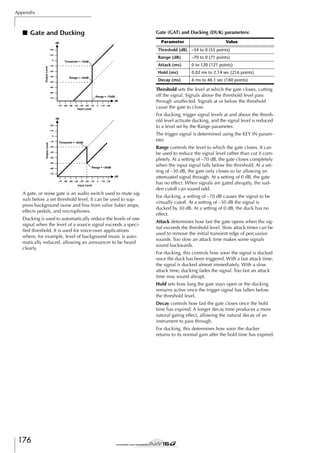


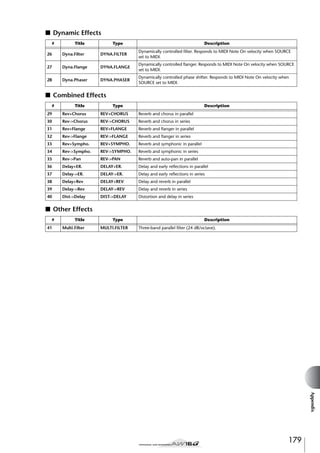
![Appendix
Effects Parameters
■ REVERB HALL, REVERB ROOM, REVERB STAGE, REVERB PLATE
Hall, room, stage, and plate simulations, all with gates.
Parameter
REV TIME
Range
Description
0.3–99.0 s
Reverb time
INI.DLY
0.0–500.0 ms
Initial delay before reverb begins
HI.RATIO
0.1–1.0
High-frequency reverb time ratio
LO.RATIO
0.1–2.4
Low-frequency reverb time ratio
DIFF.
0–10
Reverb diffusion (left–right reverb spread)
DENSITY
0–100%
Reverb density
E/R DLY
0.0–100.0 ms
Delay between early reflections and reverb
E/R BAL.
0–100%
Balance of early reflections and reverb (0% = ER, 100% = reverb)
HPF
Thru, 21.2 Hz–8.0 kHz
High-pass filter cutoff frequency
LPF
50 Hz–16.0 kHz, Thru
Low-pass filter cutoff frequency
GATE LVL
OFF, –60 to 0 dB
Level at which gate kicks in
ATTACK
0–120 ms
Gate opening speed
HOLD
0.02 ms–2.13 s
Gate open time
DECAY
6.0 ms–46.0 s
Gate closing speed
MIX BAL.
0–100 [%]
Mix balance of the effects and dry sounds
■ EARLY REF.
Early reflections.
Parameter
Range
Description
TYPE
S-Hall, L-Hall, Random,
Revers, Plate, Spring
Type of early reflection simulation
ROOMSIZE
0.1–20.0
Reflection spacing
LIVENESS
0–10
Early reflections decay characteristics (0 = dead, 10 = live)
INI.DLY
0.0–500.0 ms
Initial delay before reverb begins
DIFF.
0–10
Reverb diffusion (left–right reverb spread)
DENSITY
0–100%
Reverb density
ER NUM.
1–19
Number of early reflections
FB.GAIN
–99 to +99%
Feedback gain
HI.RATIO
0.1–1.0
High-frequency feedback ratio
HPF
Thru, 21.2 Hz–8.0 kHz
High-pass filter cutoff frequency
LPF
50 Hz–16.0 kHz, Thru
Low-pass filter cutoff frequency
MIX BAL.
0–100 [%]
Mix balance of the effects and dry sounds
■ GATE REVERB, REVERSE GATE
Early reflections with gate, and early reflections with reverse gate.
Parameter
Range
Description
TYPE
Type-A, Type-B
Type of early reflection simulation
ROOMSIZE
0.1–20.0
Reflection spacing
LIVENESS
0–10
Early reflections decay characteristics (0 = dead, 10 = live)
INI.DLY
0.0–500.0 ms
Initial delay before reverb begins
DIFF.
0–10
Reverb diffusion (left–right reverb spread)
DENSITY
0–100%
Reverb density
ER NUM.
1–19
Number of early reflections
FB.GAIN
–99 to +99%
Feedback gain
HI.RATIO
0.1–1.0
High-frequency feedback ratio
HPF
Thru, 21.2 Hz–8.0 kHz
High-pass filter cutoff frequency
LPF
50 Hz–16.0 kHz, Thru
Low-pass filter cutoff frequency
MIX BAL.
0–100 [%]
Mix balance of the effects and dry sounds
180](https://image.slidesharecdn.com/aw16ge-131126034127-phpapp02/85/Aw16-ge-180-320.jpg)
![■ MONO DELAY
Basic repeat delay.
Parameter
Range
Description
DELAY
0.0–2730.0 ms
Delay time
FB.GAIN
–99 to +99%
Feedback gain (plus values for normal-phase feedback, minus values for reverse-phase
feedback)
HI.RATIO
0.1–1.0
High-frequency feedback ratio
HPF
Thru, 21.2 Hz–8.0 kHz
High-pass filter cutoff frequency
LPF
50 Hz–16.0 kHz, Thru
Low-pass filter cutoff frequency
MIX BAL.
0–100 [%]
Mix balance of the effects and dry sounds
■ STEREO DELAY
Basic stereo delay.
Parameter
Range
Description
DELAY L
0.0–1350.0 ms
Left channel delay time
FB.G L
–99 to +99%
Left channel feedback (plus values for normal-phase feedback, minus values for
reverse-phase feedback)
DELAY R
0.0–1350.0 ms
Right channel delay time
FB.G R
–99 to +99%
Right channel feedback (plus values for normal-phase feedback, minus values for
reverse-phase feedback)
HI.RATIO
0.1–1.0
High-frequency feedback ratio
HPF
Thru, 21.2 Hz–8.0 kHz
High-pass filter cutoff frequency
LPF
50 Hz–16.0 kHz, Thru
Low-pass filter cutoff frequency
MIX BAL.
0–100 [%]
Mix balance of the effects and dry sounds
■ MOD.DELAY
Basic repeat delay with modulation.
Parameter
Range
Description
DELAY
0.0–2725.0 ms
Delay time
FB.GAIN
–99 to +99%
Feedback gain (plus values for normal-phase feedback, minus values for reverse-phase
feedback)
HI.RATIO
0.1–1.0
High-frequency feedback ratio
FREQ.
0.05–40.00 Hz
Modulation speed
DEPTH
0–100%
Modulation depth
WAVE
Sine, Tri
Modulation waveform
HPF
Thru, 21.2 Hz–8.0 kHz
High-pass filter cutoff frequency
LPF
50 Hz–16.0 kHz, Thru
Low-pass filter cutoff frequency
MIX BAL.
0–100 [%]
Mix balance of the effects and dry sounds
■ DELAY LCR
Three-tap delay (left, center, right).
Parameter
Range
Description
0.0–2730.0 ms
Left channel delay time
DELAY C
0.0–2730.0 ms
Center channel delay time
DELAY R
0.0–2730.0 ms
Right channel delay time
LEVEL L
–100 to +100%
Left channel delay level
LEVEL C
–100 to +100%
Center channel delay level
LEVEL R
–100 to +100%
Right channel delay level
FB.DLY
0.0–2730.0 ms
Feedback delay time
FB.GAIN
–99 to +99%
Feedback gain (plus values for normal-phase feedback, minus values for reverse-phase
feedback)
HI.RATIO
0.1–1.0
High-frequency feedback ratio
HPF
Thru, 21.2 Hz–8.0 kHz
High-pass filter cutoff frequency
LPF
50 Hz–16.0 kHz, Thru
Low-pass filter cutoff frequency
MIX BAL.
0–100 [%]
Mix balance of the effects and dry sounds
Appendix
DELAY L
181](https://image.slidesharecdn.com/aw16ge-131126034127-phpapp02/85/Aw16-ge-181-320.jpg)
![Appendix
■ ECHO
Stereo delay with crossed feedback loop.
Parameter
Range
Description
DELAY L
0.0–1350.0 ms
Left channel delay time
FB.DLY L
0.0–1350.0 ms
Left channel feedback delay time
FB.G L
–99 to +99%
Left channel feedback gain (plus values for normal-phase feedback, minus values for
reverse-phase feedback)
DELAY R
0.0–1350.0 ms
Right channel delay time
FB.DLY R
0.0–1350.0 ms
Right channel feedback delay time
FB.G R
–99 to +99%
Right channel feedback gain (plus values for normal-phase feedback, minus values for
reverse-phase feedback)
L->R FBG
–99 to +99%
Left to right channel feedback gain (plus values for normal-phase feedback, minus values for reverse-phase feedback)
R->L FBG
–99 to +99%
Right to left channel feedback gain (plus values for normal-phase feedback, minus values for reverse-phase feedback)
HI.RATIO
0.1–1.0
High-frequency feedback ratio
HPF
Thru, 21.2 Hz–8.0 kHz
High-pass filter cutoff frequency
LPF
50 Hz–16.0 kHz, Thru
Low-pass filter cutoff frequency
MIX BAL.
0–100 [%]
Mix balance of the effects and dry sounds
■ CHORUS
Chorus effect.
Parameter
Range
Description
FREQ.
0.05–40.00 Hz
PM DEP.
0–100%
Modulation speed
Pitch modulation depth
AM DEP.
0–100%
Amp modulation depth
MOD.DLY
0.0–500.0 ms
Modulation delay time
WAVE
Sine, Tri
Modulation waveform
LSH F
21.2–8.00 k [Hz]
Low-shelving filter frequency
LSH G
–12 to +12 [dB]
Low-shelving filter gain
EQ F
100–8.00 k [Hz]
Parametric equalizer center frequency
EQ G
–12 to +12 [dB]
Parametric equalizer gain
EQ Q
10–0.10
Parametric equalizer band width
HSH F
50.0–16.0 k [Hz]
High-shelving filter frequency
HSH G
–12 to +12 [dB]
High-shelving filter gain
MIX BAL.
0–100 [%]
Mix balance of the effects and dry sounds
■ FLANGE
Flange effect.
Parameter
Range
Description
FREQ.
0.05–40.00 Hz
DEPTH
0–100%
Modulation speed
Modulation depth
MOD.DLY
0.0–500.0 ms
Modulation delay time
FB.GAIN
–99 to +99%
Feedback gain (plus values for normal-phase feedback, minus values for reverse-phase
feedback)
WAVE
Sine, Tri
Modulation waveform
LSH F
21.2–8.00 k [Hz]
Low-shelving filter frequency
LSH G
–12 to +12 [dB]
Low-shelving filter gain
EQ F
100–8.00 k [Hz]
Parametric equalizer center frequency
EQ G
–12 to +12 [dB]
Parametric equalizer gain
EQ Q
10–0.10
Parametric equalizer band width
HSH F
50.0–16.0 k [Hz]
High-shelving filter frequency
HSH G
–12 to +12 [dB]
High-shelving filter gain
MIX BAL.
0–100 [%]
Mix balance of the effects and dry sounds
182](https://image.slidesharecdn.com/aw16ge-131126034127-phpapp02/85/Aw16-ge-182-320.jpg)
![■ SYMPHONIC
Symphonic efect.
Parameter
FREQ.
Range
0.05–40.00 Hz
Description
Modulation speed
DEPTH
0–100%
Modulation depth
MOD.DLY
0.0–500.0 ms
Modulation delay time
WAVE
Sine, Tri
Modulation waveform
LSH F
21.2–8.00 k [Hz]
Low-shelving filter frequency
LSH G
–12 to +12 [dB]
Low-shelving filter gain
EQ F
100–8.00 k [Hz]
Parametric equalizer center frequency
EQ G
–12 to +12 [dB]
Parametric equalizer gain
EQ Q
10–0.10
Parametric equalizer band width
HSH F
50.0–16.0 k [Hz]
High-shelving filter frequency
HSH G
–12 to +12 [dB]
High-shelving filter gain
MIX BAL.
0–100 [%]
Mix balance of the effects and dry sounds
■ PHASER
16-stage phaser.
Parameter
Range
Description
FREQ.
0.05–40.00 Hz
DEPTH
0–100%
Modulation speed
Modulation depth
FB.GAIN
–99 to +99%
Feedback gain (plus values for normal-phase feedback, minus values for reverse-phase
feedback)
OFFSET
0–100
Lowest phase-shifted frequency offset
STAGE
2, 4, 6, 8, 10, 12, 14, 16
Number of phase shift stages
LSH F
21.2–8.00 k [Hz]
Low-shelving filter frequency
LSH G
–12 to +12 [dB]
Low-shelving filter gain
HSH F
50.0–16.0 k [Hz]
High-shelving filter frequency
HSH G
–12 to +12 [dB]
High-shelving filter gain
MIX BAL.
0–100 [%]
Mix balance of the effects and dry sounds
■ AUTOPAN
Auto-panner.
Parameter
Range
Description
FREQ.
0.05–40.00 Hz
Modulation speed
DEPTH
0–100%
Modulation depth
DIR.
*1
Panning direction
WAVE
Sine, Tri, Square
Modulation waveform
LSH F
21.2–8.00 k [Hz]
Low-shelving filter frequency
LSH G
–12 to +12 [dB]
Low-shelving filter gain
EQ F
100–8.00 k [Hz]
Parametric equalizer center frequency
EQ G
–12 to +12 [dB]
Parametric equalizer gain
EQ Q
10–0.10
Parametric equalizer band width
HSH F
50.0–16.0 k [Hz]
High-shelving filter frequency
HSH G
–12 to +12 [dB]
High-shelving filter gain
MIX BAL.
0–100 [%]
Mix balance of the effects and dry sounds
*1. L<->R, L—>R, L<—R, Turn L, Turn R
Appendix
183](https://image.slidesharecdn.com/aw16ge-131126034127-phpapp02/85/Aw16-ge-183-320.jpg)
![Appendix
■ TREMOLO
Tremolo effect.
Parameter
Range
Description
FREQ.
0.05–40.00 Hz
Modulation speed
DEPTH
0–100%
Modulation depth
WAVE
Sine, Tri, Square
Modulation waveform
LSH F
21.2–8.00 k [Hz]
Low-shelving filter frequency
LSH G
–12 to +12 [dB]
Low-shelving filter gain
EQ F
100–8.00 k [Hz]
Parametric equalizer center frequency
EQ G
–12 to +12 [dB]
Parametric equalizer gain
EQ Q
10–0.10
Parametric equalizer band width
HSH F
50.0–16.0 k [Hz]
High-shelving filter frequency
HSH G
–12 to +12 [dB]
High-shelving filter gain
MIX BAL.
0–100 [%]
Mix balance of the effects and dry sounds
■ HQ.PITCH (Effect 2 only)
High-quality pitch shifter.
Parameter
Range
Description
PITCH
–12 to +12 semitones
Pitch shift
FINE
–50 to +50 cents
Pitch shift fine
DELAY
0.0–1000.0 ms
Delay time
FB.GAIN
–99 to +99%
Feedback gain (plus values for normal-phase feedback, minus values for reverse-phase
feedback)
MODE
1–10
Pitch shift precision
MIX BAL.
0–100 [%]
Mix balance of the effects and dry sounds
■ DUAL PITCH
Twin-voice pitch shifter.
Parameter
Range
Description
PITCH 1
–24 to +24 semitones
Channel 1 pitch shift
FINE 1
–50 to +50 cents
Channel 1 pitch shift fine
PAN 1
L16–1, C, R1–16
Channel 1 panpot
DELAY 1
0.0–1000.0 ms
Channel 1 delay time
FB.G 1
–99 to +99%
Channel 1 feedback gain (plus values for normal-phase feedback, minus values for
reverse-phase feedback)
LEVEL 1
–100 to +100%
Channel 1 level (plus values for normal phase, minus values for reverse phase)
PITCH 2
–24 to +24 semitones
Channel 2 pitch shift
FINE 2
–50 to +50 cents
Channel 2 pitch shift fine
PAN 2
L16–1, C, R1–16
Channel 2 panpot
DELAY 2
0.0–1000.0 ms
Channel 2 delay time
FB.G 2
–99 to +99%
Channel 2 feedback gain (plus values for normal-phase feedback, minus values for
reverse-phase feedback)
LEVEL 2
–100 to +100%
Channel 2 level (plus values for normal phase, minus values for reverse phase)
MODE
1–10
Pitch shift precision
MIX BAL.
0–100 [%]
Mix balance of the effects and dry sounds
184](https://image.slidesharecdn.com/aw16ge-131126034127-phpapp02/85/Aw16-ge-184-320.jpg)
![■ ROTARY
Rotary speaker simulator.
Parameter
Range
Description
ROTATE
STOP, START
Rotation stop, start
SPEED
SLOW, FAST
Rotation speed (see SLOW and FAST parameters)
DRIVE
0–100
Overdrive level
ACCEL
0–10
Accelation at speed changes
LOW
0–100
Low-frequency filter
HIGH
0–100
High-frequency filter
SLOW
0.05–10.00 Hz
SLOW rotation speed
FAST
0.05–10.00 Hz
FAST rotation speed
MIX BAL.
0–100 [%]
Mix balance of the effects and dry sounds
■ RING MOD.
Ring modulator.
Parameter
Range
Description
SOURCE
OSC, SELF
Modulation source: oscillator or input signal
OSC FREQ
0.0–5000.0 Hz
Oscillator frequency
FM FREQ
0.05–40.00 Hz
Oscillator frequency modulation speed
FM DEPTH
0–100%
Oscillator frequency modulation depth
MIX BAL.
0–100 [%]
Mix balance of the effects and dry sounds
■ MOD.FILTER
LFO modulation-type filter.
Parameter
Range
Description
FREQ.
0.05–40.00 Hz
DEPTH
0–100%
Modulation speed
Modulation depth
TYPE
LPF, HPF, BPF
Filter type: low pass, high pass, band pass
OFFSET
0–100
Filter frequency offset
RESO.
0–20
Filter resonance
PHASE
0.00–354.38°
Left-channel modulation and right-channel modulation phase difference
LEVEL
0–100
Output level
MIX BAL.
0–100 [%]
Mix balance of the effects and dry sounds
■ DISTORTION
Distortion effect.
Parameter
DST TYPE
Range
DST1, DST2, OVD1,
OVD2, CRUNCH
Description
Distortion type (DST = distortion, OVD = overdrive)
DRIVE
0–100
Distortion drive
MASTER
0–100
Master volume
TONE
–10 to +10
Tone
N.GATE
0–20
Noise reduction
MIX BAL.
0–100 [%]
Mix balance of the effects and dry sounds
Appendix
185](https://image.slidesharecdn.com/aw16ge-131126034127-phpapp02/85/Aw16-ge-185-320.jpg)
![Appendix
■ AMP SIMULATE
Guitar Amp Simulator.
Parameter
Range
Description
AMP TYPE
*1
Guitar amp simulation type
DST TYPE
DST1, DST2, OVD1,
OVD2, CRUNCH
Distortion type (DST = distortion, OVD = overdrive)
N.GATE
0–20
Noise reduction
DRIVE
0–100
Distortion drive
MASTER
0–100
Master volume
CAB DEP
0–100%
Speaker cabinet simulation depth
BASS
0–100
Bass tone control
MIDDLE
0–100
Middle tone control
TREBLE
0–100
High tone control
EQ F
99–8.0 kHz
Parametric equalizer frequency
EQ G
–12 to +12 dB
Parametric equalizer gain
EQ Q
10.0–0.10
Parametric equalizer bandwidth
MIX BAL.
0–100 [%]
Mix balance of the effects and dry sounds
*1. STK-M1, STK-M2, THRASH, MIDBST, CMB-PG, CMB-VR, CMB-DX, CMB-TW, MINI, FLAT
■ DYNA.FILTER
Dynamically controlled filter.
Parameter
Range
Description
SOURCE
INPUT, MIDI
SENSE
0–100
Control source: input signal or MIDI note on velocity
Sensitivity
TYPE
LPF, HPF, BPF
Filter type
OFFSET
0–100
Filter frequency offset
RESO.
0–20
Filter resonance
DIR.
UP, DOWN
Upward or downward frequency change
DECAY
6.0 ms–46.0 s
Filter frequency change decay speed
LEVEL
0–100
Output Level
MIX BAL.
0–100 [%]
Mix balance of the effects and dry sounds
■ DYNA.FLANGE
Dynamically controlled flanger.
Parameter
SOURCE
Range
INPUT, MIDI
Description
Control source: input signal or MIDI note on velocity
SENSE
0–100
Sensitivity
FB.GAIN
–99 to +99%
Feedback gain (plus values for normal-phase feedback, minus values for reverse-phase
feedback)
OFFSET
0–100
Delay time offset
DIR.
UP, DOWN
Upward or downward frequency change
DECAY
6.0 ms–46.0 s
Decay speed
LSH F
21.2–8.00 k [Hz]
Low-shelving filter frequency
LSH G
–12 to +12 [dB]
Low-shelving filter gain
EQ F
100–8.00 k [Hz]
Parametric equalizer center frequency
EQ G
–12 to +12 [dB]
Parametric equalizer gain
EQ Q
10–0.10
Parametric equalizer band width
HSH F
50.0–16.0 k [Hz]
High-shelving filter frequency
HSH G
–12 to +12 [dB]
High-shelving filter gain
MIX BAL.
0–100 [%]
Mix balance of the effects and dry sounds
186](https://image.slidesharecdn.com/aw16ge-131126034127-phpapp02/85/Aw16-ge-186-320.jpg)
![■ DYNA.PHASER
Dynamically controlled phaser.
Parameter
SOURCE
Range
INPUT, MIDI
Description
Control source: input signal or MIDI note on velocity
SENSE
0–100
Sensitivity
FB.GAIN
–99 to +99%
Feedback gain (plus values for normal-phase feedback, minus values for reverse-phase
feedback)
OFFSET
0–100
Lowest phase-shifted frequency offset
STAGE
2, 4, 6, 8, 10, 12, 14, 16
Number of phase shift stages
DIR.
UP, DOWN
Upward or downward frequency change
DECAY
6.0 ms–46.0 s
Decay speed
LSH F
21.2–8.00 k [Hz]
Low-shelving filter frequency
LSH G
–12 to +12 [dB]
Low-shelving filter gain
HSH F
50.0–16.0 k [Hz]
High-shelving filter frequency
HSH G
–12 to +12 [dB]
High-shelving filter gain
MIX BAL.
0–100 [%]
Mix balance of the effects and dry sounds
■ REV+CHORUS
Reverb and chorus effects in parallel.
Parameter
REV TIME
Range
Description
0.3–99.9 s
Reverb time
INI.DLY
0.0–500.0 ms
Initial delay before reverb begins
HI.RATIO
0.1–1.0
High-frequency reverb time ratio
DIFF.
0–10
Reverb diffusion (left-right reverb spreed)
DENSITY
0–100%
Reverb density
HPF
Thru, 21.2 Hz–8.0 kHz
High-pass filter cutoff frequency
LPF
50 Hz–16.0 kHz, Thru
Low-pass filter cutoff frequency
FREQ.
0.05–40.00 Hz
Modulation speed
PM DEP.
0–100%
Pitch modulation depth
AM DEP.
0–100%
Amp modulation depth
MOD.DLY
0.0–500.0 ms
Modulation delay time
WAVE
Sine, Tri
Modulation waveform
REV/CHO
0–100%
Reverb and chorus balance (0% = chorus, 100% = reverb)
MIX BAL.
0–100 [%]
Mix balance of the effects and dry sounds
■ REV->CHORUS
Reverb and chorus effects in series.
Parameter
REV TIME
Range
Description
0.3–99.9 s
Reverb time
INI.DLY
0.0–500.0 ms
Initial delay before reverb begins
HI.RATIO
0.1–1.0
High-frequency reverb time ratio
DIFF.
0–10
Reverb diffusion (left-right reverb spreed)
DENSITY
0–100%
Reverb density
HPF
Thru, 21.2 Hz–8.0 kHz
High-pass filter cutoff frequency
LPF
50 Hz–16.0 kHz, Thru
Low-pass filter cutoff frequency
FREQ.
0.05–40.00 Hz
Modulation speed
PM DEP.
0–100%
Pitch modulation depth
AM DEP.
0–100%
Amp modulation depth
MOD.DLY
0.0–500.0 ms
Modulation delay time
Sine, Tri
Modulation waveform
0–100%
Reverb and chorused reverb balance (0% = chorused reverb, 100% = reverb)
MIX BAL.
0–100 [%]
Mix balance of the effects and dry sounds
Appendix
WAVE
REV.BAL
187](https://image.slidesharecdn.com/aw16ge-131126034127-phpapp02/85/Aw16-ge-187-320.jpg)
![Appendix
■ REV+FLANGE
Reverb and flanger effects in parallel.
Parameter
REV TIME
Range
Description
0.3–99.9 s
Reverb time
INI.DLY
0.0–500.0 ms
Initial delay before reverb begins
HI.RATIO
0.1–1.0
High-frequency reverb time ratio
DIFF.
0–10
Reverb diffusion (left-right reverb spreed)
DENSITY
0–100%
Reverb density
HPF
Thru, 21.2 Hz–8.0 kHz
High-pass filter cutoff frequency
LPF
50 Hz–16.0 kHz, Thru
Low-pass filter cutoff frequency
FREQ.
0.05–40.00 Hz
Modulation speed
DEPTH
0–100%
Modulation depth
MOD.DLY
0.0–500.0 ms
Modulation delay time
FB.GAIN
–99 to +99%
Feedback gain (plus values for normal-phase feedback, minus values for reverse-phase
feedback)
WAVE
Sine, Tri
Modulation waveform
REV/FLG
0–100%
Reverb and flange balance (0% = flange, 100% = reverb)
MIX BAL.
0–100 [%]
Mix balance of the effects and dry sounds
■ REV->FLANGE
Reverb and flanger effects in series.
Parameter
Range
Description
REV TIME
0.3–99.9 s
Reverb time
INI.DLY
0.0–500.0 ms
Initial delay before reverb begins
HI.RATIO
0.1–1.0
High-frequency reverb time ratio
DIFF.
0–10
Reverb diffusion (left-right reverb spreed)
DENSITY
0–100%
Reverb density
HPF
Thru, 21.2 Hz–8.0 kHz
High-pass filter cutoff frequency
LPF
50 Hz–16.0 kHz, Thru
Low-pass filter cutoff frequency
FREQ.
0.05–40.00 Hz
Modulation speed
DEPTH
0–100%
Modulation depth
MOD.DLY
0.0–500.0 ms
Modulation delay time
FB.GAIN
–99 to +99%
Feedback gain (plus values for normal-phase feedback, minus values for reverse-phase
feedback)
WAVE
Sine, Tri
Modulation waveform
REV.BAL
0–100%
Reverb and flanged reverb balance (0% = flanged reverb, 100% = reverb)
MIX BAL.
0–100 [%]
Mix balance of the effects and dry sounds
■ REV+SYMPHO.
Reverb and symphonic effects in parallel.
Parameter
REV TIME
Range
Description
0.3–99.9 s
Reverb time
INI.DLY
0.0–500.0 ms
Initial delay before reverb begins
HI.RATIO
0.1–1.0
High-frequency reverb time ratio
DIFF.
0–10
Reverb diffusion (left-right reverb spreed)
DENSITY
0–100%
Reverb density
HPF
Thru, 21.2 Hz–8.0 kHz
High-pass filter cutoff frequency
LPF
50 Hz–16.0 kHz, Thru
Low-pass filter cutoff frequency
FREQ.
0.05–40.00 Hz
Modulation speed
DEPTH
0–100%
Modulation depth
MOD.DLY
0.0–500.0 ms
Modulation delay time
WAVE
Sine, Tri
Modulation waveform
REV/SYM
0–100%
Reverb and symphonic balance (0% = symphonic, 100% = reverb)
MIX BAL.
0–100 [%]
Mix balance of the effects and dry sounds
188](https://image.slidesharecdn.com/aw16ge-131126034127-phpapp02/85/Aw16-ge-188-320.jpg)
![■ REV->SYMPHO.
Reverb and symphonic effects in series.
Parameter
REV TIME
Range
Description
0.3–99.9 s
Reverb time
INI.DLY
0.0–500.0 ms
Initial delay before reverb begins
HI.RATIO
0.1–1.0
High-frequency reverb time ratio
DIFF.
0–10
Reverb diffusion (left-right reverb spreed)
DENSITY
0–100%
Reverb density
HPF
Thru, 21.2 Hz–8.0 kHz
High-pass filter cutoff frequency
LPF
50 Hz–16.0 kHz, Thru
Low-pass filter cutoff frequency
FREQ.
0.05–40.00 Hz
Modulation speed
DEPTH
0–100%
Modulation depth
MOD.DLY
0.0–500.0 ms
Modulation delay time
WAVE
Sine, Tri
Modulation waveform
REV.BAL
0–100%
Reverb and symphonic reverb balance (0% = symphonic reverb, 100% = reverb)
MIX BAL.
0–100 [%]
Mix balance of the effects and dry sounds
■ REV->PAN
Reverb and auto-pan effects in parallel.
Parameter
Range
Description
REV TIME
0.3–99.9 s
Reverb time
INI.DLY
0.0–500.0 ms
Initial delay before reverb begins
HI.RATIO
0.1–1.0
High-frequency reverb time ratio
DIFF.
0–10
Reverb diffusion (left-right reverb spreed)
DENSITY
0–100%
Reverb density
HPF
Thru, 21.2 Hz–8.0 kHz
High-pass filter cutoff frequency
LPF
50 Hz–16.0 kHz, Thru
Low-pass filter cutoff frequency
FREQ.
0.05–40.00 Hz
Modulation speed
DEPTH
0–100%
Modulation depth
DIR.
*1
Panning direction
WAVE
Sine, Tri, Square
Modulation waveform
REV BAL.
0–100%
Reverb and panned reverb balance (0% = panned reverb, 100% = reverb)
MIX BAL.
0–100 [%]
Mix balance of the effects and dry sounds
*1. L<->R, L—>R, L<—R, Turn L, Turn R
■ DELAY+ER.
Delay and early reflections effects in parallel.
Parameter
Range
Description
DELAY L
0.0–1000.0 ms
Left channel delay time
DELAY R
0.0–1000.0 ms
Right channel delay time
FB.DLY
0.0–1000.0 ms
Feedback delay time
FB.GAIN
–99 to +99%
Feedback gain (plus values for normal-phase feedback, minus values for reverse-phase
feedback)
HI.RATIO
0.1–1.0
High-frequency feedback ratio
TYPE
S-Hall, L-Hall, Random,
Revers, Plate, Spring
Type of early reflection simulation
ROOMSIZE
0.1–20.0
Reflection spacing
LIVENESS
0–10
Early reflections decay characteristics (0 = dead, 10 = live)
INI.DLY
0.0–500.0 ms
Initial delay before reverb begins
0–10
Reverb diffusion (left-right reverb spreed)
DENSITY
0–100%
Reverb density
ER NUM.
1–19
Number of early reflections
HPF
Thru, 21.2 Hz–8.0 kHz
High-pass filter cutoff frequency
LPF
50 Hz–16.0 kHz, Thru
Low-pass filter cutoff frequency
DLY/ER
0–100%
Delay and early reflections balance (0% = early reflections, 100% = delay)
MIX BAL.
0–100 [%]
Mix balance of the effects and dry sounds
Appendix
DIFF.
189](https://image.slidesharecdn.com/aw16ge-131126034127-phpapp02/85/Aw16-ge-189-320.jpg)
![Appendix
■ DELAY->ER.
Delay and early reflections effects in series.
Parameter
Range
Description
DELAY L
0.0–1000.0 ms
Left channel delay time
DELAY R
0.0–1000.0 ms
Right channel delay time
FB.DLY
0.0–1000.0 ms
Feedback delay time
FB.GAIN
–99 to +99%
Feedback gain (plus values for normal-phase feedback, minus values for reverse-phase
feedback)
HI.RATIO
0.1–1.0
High-frequency feedback ratio
TYPE
S-Hall, L-Hall, Random,
Revers, Plate, Spring
Type of early reflection simulation
ROOMSIZE
0.1–20.0
Reflection spacing
LIVENESS
0–10
Early reflections decay characteristics (0 = dead, 10 = live)
INI.DLY
0.0–500.0 ms
Initial delay before reverb begins
DIFF.
0–10
Reverb diffusion (left-right reverb spreed)
DENSITY
0–100%
Reverb density
ER NUM.
1–19
Number of early reflections
HPF
Thru, 21.2 Hz–8.0 kHz
High-pass filter cutoff frequency
LPF
50 Hz–16.0 kHz, Thru
Low-pass filter cutoff frequency
DLY.BAL
0–100%
Delay and early reflected delay balance (0% = early reflected delay, 100% = delay)
MIX BAL.
0–100 [%]
Mix balance of the effects and dry sounds
■ DELAY+REV
Delay and reverb effects in parallel.
Parameter
Range
Description
DELAY L
0.0–1000.0 ms
Left channel delay time
DELAY R
0.0–1000.0 ms
Right channel delay time
FB.DLY
0.0–1000.0 ms
Feedback delay time
FB.GAIN
–99 to +99%
Feedback gain (plus values for normal-phase feedback, minus values for reverse-phase
feedback)
DELAY HI
0.1–1.0
Delay high-frequency feedback ratio
REV TIME
0.3–99.9 s
Reverb time
INI.DLY
0.0–500.0 ms
Initial delay before reverb begins
REV HI
0.1–1.0
High-frequency reverb time ratio
DIFF.
0–10
Reverb diffusion (left-right reverb spreed)
DENSITY
0–100%
Reverb density
HPF
Thru, 21.2 Hz–8.0 kHz
High-pass filter cutoff frequency
LPF
50 Hz–16.0 kHz, Thru
Low-pass filter cutoff frequency
DLY/REV
0–100%
Delay and reverb balance (0% = reverb, 100% = delay)
MIX BAL.
0–100 [%]
Mix balance of the effects and dry sounds
190](https://image.slidesharecdn.com/aw16ge-131126034127-phpapp02/85/Aw16-ge-190-320.jpg)
![■ DELAY->REV
Delay and reverb effects in series.
Parameter
Range
Description
DELAY L
0.0–1000.0 ms
Left channel delay time
DELAY R
0.0–1000.0 ms
Right channel delay time
FB.DLY
0.0–1000.0 ms
Feedback delay time
FB.GAIN
–99 to +99%
Feedback gain (plus values for normal-phase feedback, minus values for reverse-phase
feedback)
DELAY HI
0.1–1.0
Delay high-frequency feedback ratio
REV TIME
0.3–99.9 s
Reverb time
INI.DLY
0.0–500.0 ms
Initial delay before reverb begins
REV HI
0.1–1.0
High-frequency reverb time ratio
DIFF.
0–10
Reverb diffusion (left-right reverb spreed)
DENSITY
0–100%
Reverb density
HPF
Thru, 21.2 Hz–8.0 kHz
High-pass filter cutoff frequency
LPF
50 Hz–16.0 kHz, Thru
Low-pass filter cutoff frequency
DLY.BAL
0–100%
Delay and delayed reverb balance (0% = delayed reverb, 100% = delay)
MIX BAL.
0–100 [%]
Mix balance of the effects and dry sounds
■ DIST->DELAY
Distortion and delay effects in series.
Parameter
DST TYPE
Range
DST1, DST2, OVD1,
OVD2, CRUNCH
Description
Distortion type (DST = distortion, OVD = overdrive)
DRIVE
0–100
Distortion drive
MASTER
0–100
Master volume
TONE
–10 to +10
Tone control
N.GATE
0–20
Noise reduction
DELAY
0.0–2725.0 ms
Delay time
FB.GAIN
–99 to +99%
Feedback gain (plus values for normal-phase feedback, minus values for reverse-phase
feedback)
HI.RATIO
0.1–1.0
High-frequency feedback ratio
FREQ.
0.05–40.00 Hz
Modulation speed
DEPTH
0–100%
Modulation depth
DLY BAL
0–100%
Distortion and delay balance (0% = distortion, 100% = delayed distortion)
MIX BAL.
0–100 [%]
Mix balance of the effects and dry sounds
■ MULTI FILTER
Three-band parallel filter (24 dB/octave)
Parameter
Range
Description
HPF, LPF, BPF
Filter 1 type: low pass, high pass, band pass
TYPE 2
HPF, LPF, BPF
Filter 2 type: low pass, high pass, band pass
TYPE 3
HPF, LPF, BPF
Filter 3 type: low pass, high pass, band pass
FREQ. 1
28 Hz–16.0 kHz
Filter 1 frequency
FREQ. 2
28 Hz–16.0 kHz
Filter 2 frequency
FREQ. 3
28 Hz–16.0 kHz
Filter 3 frequency
LEVEL 1
0–100
Filter 1 level
LEVEL 2
0–100
Filter 2 level
LEVEL 3
0–100
Filter 3 level
RESO. 1
0–20
Filter 1 resonance
RESO. 2
0–20
Filter 2 resonance
RESO. 3
0–20
Filter 3 resonance
MIX BAL.
0–100 [%]
Mix balance of the effects and dry sounds
Appendix
TYPE 1
191](https://image.slidesharecdn.com/aw16ge-131126034127-phpapp02/85/Aw16-ge-191-320.jpg)
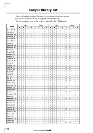

![Appendix
Troubleshooting
If the AW16G does not operate as you expect, or if you suspect a
problem, please refer to the following points and take the appropriate action.
■ Power does not turn on
• Is the AC adaptor connected to an AC outlet of the
correct voltage?
• Is the POWER switch turned ON?
• If the power still does not turn on, please contact
your Yamaha dealer.
■ LCD display is dim or dark
• Use the contrast knob located at the lower right of
the screen to adjust the contrast.
■ Can’t use the [DATA/JOG] dial to control on-screen
parameters
• The [JOG ON] key may be on.
• Some parameters cannot be operated in certain
states, such as while the recorder is running.
No sound
■
•
•
•
•
•
•
•
•
No sound, or sound is too faint
Are speakers or headphones connected correctly?
Is your amp and other external devices turned on?
Does the stereo output channel meter move?
Is the stereo output channel fader raised? Is it turned
on?
The EQ gain may be set to an extremely low value.
The dynamics processor may be set to an extreme
threshold or ratio.
If you are connecting an electric guitar, is it connected to the Hi-Z jack?
Is the attenuator of the EQ screen or VIEW screen
raised?
* Check the level (meter movement) in the METER page
of the VIEW screen.
* If you press the [SEL] key in the MONITOR screen INIT
page, that channel will be initialized to default values
that allow sound to be output.
* If DIGITAL IN is set to other than DISABLE in the UTILITY
screen D.IN HDD page, and no signal is being input to
the DIGITAL INPUT jack, a message of “WRONG WORD
CLOCK” will appear, and sound will not be output.
■ Input sound is not output
• Is the signal from the external device being input?
• The connection cable from the external device may
be broken.
• Is the [GAIN] control set to an appropriate level?
• Is the input channel fader raised? Is it turned on?
• The input channel may have been set to DIGITAL IN.
• When recording, is the recording-destination track
fader (which adjusts the monitor level) raised?
* If you are recording, the sound of that input channel
will not be heard during playback.
194
■
•
•
•
Recorded sound is not output
Has audio data been recorded on the recorder?
Is the virtual track set to the track that was recorded?
A recorded region shorter than 10 msec will not be
played back.
• Tracks 1–16 will not play back if the AW16G is in
Stereo Track, Sound Clip, or Audio CD playback
mode.
■ Can’t play back the STEREO track
• Is the stereo track turned on in the MONITOR screen
ST.TRACK page?
■ Metronome cannot be heard
• The metronome sound is normally sent only to the
MONITOR OUT and headphones.
• The metronome will not sound while the recorder is
stopped.
• In Sound Clip mode, the metronome will sound only
during recording.
Can’t record, something is wrong with
the recorded sound
■ Can’t record
• Is there sufficient free space on the internal hard disk?
* You can check the remaining recordable time by setting
the counter display to REMAIN in the SONG screen
SETUP page.
• The song may be protected.
• The stereo track may be in playback mode.
• Is the input signal routed appropriately to the
recorder?
• Check the recording-source and recording-destination in the QUICK NAVIGATE page RECORD screen?
• DIGITAL REC may have been turned OFF in the
UTILITY screen PREFER page.
• Please read and understand the copyright warning (→
p. 5) before using digital input signals.
■ Can’t record on the STEREO track
• It is not possible to record on the STEREO track while
recording on other tracks.
■ Noise is present in the recorded signal
• The oscillator may be functioning.
• Does the word clock setting match for the AW16G
and the external device(s)?
• Go to the QUICK NAVIGATE screen RECORD page
and check the recording-source and recording-destination.](https://image.slidesharecdn.com/aw16ge-131126034127-phpapp02/85/Aw16-ge-194-320.jpg)
![Something wrong with the sound
■ Signal from the INPUT 8 jack is too loud
• A conventional line-level signal may be connected to
the Hi-Z jack.
■ Sound is distorted
• Is the [GAIN] control set correctly?
• The connection cable from the external device may
be broken.
• The fader of the input channel or monitor channel
may be raised excessively.
• The stereo output channel fader may be raised excessively.
• The stereo output channel attenuator may be raised
excessively.
• The EQ or dynamics processor may have been set to
produce an extreme gain boost.
• Did you record at an appropriate level?
• Is the word clock setting correct for both the AW16G
and the external device(s)?
• An effect such as Distortion or Amp Simulate may be
in use.
* Go to the VIEW screen METER page and check the level
(meter movement).
■ The volume of a particular channel increases or
decreases
• Are the dynamics processor settings appropriate?
• A scene recall may be specified in the SONG screen
TEMPO MAP.
■ Can’t store a scene
• The store-destination scene may be protected.
• A scene cannot be stored in scene number 00.
■ Can’t reproduce a scene
• One or more channels may be set to Recall Safe.
■ Can’t save to a library
• It is not possible to save to the factory-preset libraries.
■ Meters move even though the faders are lowered
• The meter display may be set to PRE FADER.
■ Moving a fader does not change the level
• In the [VIEW] screen FADER page, check whether the
display moves in correspondence with fader operations.
* You cannot control the level until the panel fader position matches the position shown in the display.
• In the UTILITY screen PREFER page, is FADER FLIP
set appropriately?
* When the power is turned on, FADER FLIP will be set to
TRACK.
• The fader may be set to PRE FADE in AUX.
■ Pairing was specified, but the signal is monaural
• Is the odd-numbered channel panned far left and the
even-numbered channel panned far right?
■ Signal is delayed
• An effect such as delay may be inserted.
■ Playback pitch is wrong
• VARI may be selected.
• Is the synchronized external device operating on the
same sampling frequency (44.1 kHz)?
• Is the master device operating in a stable way?
• You may have executed the EDIT screen PITCH command.
• Is an effect such as HQ.Pitch or Dual Pitch selected
for a monitor channel?
Recorder operations
■ When you press the [PLAY] key it blinks, and playback does not occur
• Is the AW16G set to MTC SLAVE?
* Access the UTILITY screen MIDI page, and check the
setting.
■ Something goes wrong with the sound when you use
the [FF] key or [REW] key
• Differences in the number of simultaneously played
tracks will affect the way in which the sound is heard
when these controls are operated.
■ Can’t edit a recorded track
• The song may be protected.
• Have you selected the virtual track that you
recorded?
■ Editing results are not heard in the sound
• Have you selected the virtual track that you
recorded?
• Are you using the appropriate editing command? *
* For details on editing commands, refer to “EDIT
screen.”
■ Counter display is not 0 when you return to the
beginning of the song
• The display mode may be set to REMAIN (remaining
recording time).
• If the display mode is set to REL (relative time), the
start point may be specified.
* Go to the SONG screen SETUP, POINT page and check
the settings.
■ Display indicates DISK FULL, MEMORY FULL, or
TOO MANY REGIONS, and you cannot record or
edit
• There is insufficient free space, or too many recording regions. Erase unneeded tracks and then perform
the Optimize operation to obtain more free space.
■ The display indicates DISK BUSY during playback
• It is possible that the recorded data has become fragmented, so that it cannot be read fast enough. You
can try measures such as re-recording, deleting
tracks, or backing up the data and then formatting the
hard disk.
195
Appendix
■ Pairing was specified, but the signal phase does not
match
• Even when channels are paired, the phase setting is
not linked.
■ Can’t use the internal effects
• Effect BYPASS may be turned ON.
• The effect may have been inserted into a different
channel.
• Are the level of EFF.RTN 1, 2 faders raised?
• 019. HQ. Pitch can be used only with EFFECT 2.
• These do not affect the stereo track, sound clip, or
audio CD playback.](https://image.slidesharecdn.com/aw16ge-131126034127-phpapp02/85/Aw16-ge-195-320.jpg)


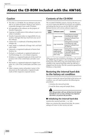
![■ Loading the demo song and sample
library
Installing a remote file
1
2
3
Please be aware that the menu names and screens that
appear in the explanation below may differ depending
on the software you are using.
Insert the included CD-ROM into the CD-RW
drive of the AW16G.
In the Work Navigate section, repeatedly
press the [CD] key to access the RESTORE
page.
Make sure that the cursor is located at the
READ CD INFO button, and press the
[ENTER] key.
Loading from the CD-ROM will begin. When loading is finished, the contents of the display will
change as follows.
■ Windows users
In order to use a remote file, the corresponding software
must be installed.
Installing the Cubase remote setup file
1
2
3
Start up Cubase.
In the menu bar, click [Option] → [Remote
Setup] → [Setup].
The VST Remote window will appear. Make
the following settings and click the [OK] button.
Remote: Generic
Remote
4
Move the cursor to the DISABLE button and
press the [ENTER] key.
5
Move the cursor to the PAD button and press
the [ENTER] key.
6
7
8
9
Input: (the MIDI
device you are using)
The DISABLE button will change to ENABLE, and
the symbol at the right of the list will change to ●.
Output: (the MIDI
device you are using)
Once again, loading from the CD-ROM will begin.
When loading is finished, the contents of the display will change as follows.
Move the cursor to the ALL button and press
the [ENTER] key.
Note
The content that is shown for “Input” and “Output” will
depend on the MIDI device(s) you are using. For details,
refer to the owner’s manual for the MIDI device(s) you
are using.
4
5
The Generic Remote window will appear.
Click the [EDIT] button.
6
A dialog box like the following will appear.
Select the Cubase remote setup file (Yamaha
AW16G Remote.xml) from the included CDROM, and click the [Open] button.
7
Close the Generic Remote Setup window.
The Generic Remote Setup window will
appear. Click the [Import] button.
Move the cursor to the DISABLE button and
press the [ENTER] key.
The DISPLAY button will change to ENABLE, and all
symbols at the right of the list will change to ●.
This selects all songs and sample libraries.
Move the cursor to the EXECUTE button and
press the [ENTER] key.
A popup window will ask you for confirmation, so move the cursor to the OK button or
CANCEL button, and press the [ENTER] key.
While the Restore operation is being executed, the
state of progress will be shown in a popup window.
When this popup window closes, the operation has
been completed.
Appendix
201](https://image.slidesharecdn.com/aw16ge-131126034127-phpapp02/85/Aw16-ge-201-320.jpg)
![Appendix
Installing the Logic preference file
1
2
3
4
Start up Logic.
In the menu bar, click [Option] → [Settings]
→ [Key Commands...].
The Key Commands window will open. In
the menu bar, click [Option] → [Import Key
Commands...].
A dialog box will appear. Select the Logic
preference file (Logic32.prf) from the
included CD-ROM, and click the [Open] button.
SONAR 2/CakewalkProAudio template (Loading the
template)
1
2
Start up SONAR 2/CakewalkProAudio.
If you are using SONAR 2:
In the menu bar, click [File] → [Open].
If you are using Cakewalk:
In the menu bar, click [File] → [New].
3
When you import the file, the following settings will
be made.
If you are using SONAR 2:
The “Open file” dialog box will appear. Choose
Cakewalk template files as the type of file to be
loaded. From the list in the dialog box, choose
Yamaha AW16G Remote and click the [OK] button.
If you are using Cakewalk:
The “New Project File” dialog box will appear.
From the list in the dialog box, choose Yamaha
AW16G Remote, and click the [OK] button.
The template will be loaded, and three windows
will appear; the Track window, Control window,
and Panel window.
4
5
Please note that all the previously-specified key
commands will be initialized. If you do not want to
change your existing user key command settings,
you can manually make the MIDI channel and CC#
settings shown above.
SONAR 2/CakewalkProAudio template (Installation/settings)
1
2
3
4
Copy the template to the folder in which
SONAR 2/CakewalkProAudio is installed.
Start up SONAR 2/CakewalkProAudio.
In the menu bar, click [Option] → [Audio].
The Cakewalk DirectShow Audio dialog box
will appear. Change the “Number of Aux
Busses” (from the default value of 2) to [3],
and click the [OK] button.
This completes preparations for the template.
In the menu bar, click [Option] → [MIDI
Devices].
The MIDI Ports window will open. In the
Input Ports field, assign the MIDI device that
you are using.
This completes preparations for controlling SONAR 2/
CakewalkProAudio from the AW16G.
● If you changed the track structure from the default
settings of the template ...
With the Yamaha AW16G Remote template started,
click the [CONFIG] button in the panel window.
A cluster will open at the right.
Drag the [SET MIDI First Track] knob to the first track
number of the MIDI tracks.
* If you use this template, you will not be able to control the tracks correctly from the AW16G unless the
MIDI tracks are continuous from 1—16.
* If you set the value to an invalid track (an unused
track), the panel knobs, buttons, or sliders may be
shaded. If this occurs, set the value back to the correct
track.
Pro Tools software
You can remotely control the Pro Tools software from the
AW16G. No special setting file is required. The setting
procedure is the same as for the Mac version.
Refer to “Macintosh users” → “Pro Tools software” (→
p. 203).
202](https://image.slidesharecdn.com/aw16ge-131126034127-phpapp02/85/Aw16-ge-202-320.jpg)
![■ Macintosh users
In order to use a remote file, the corresponding software
must be installed.
Installing the Cubase remote setup file
For Cubase, the procedure is the same as for the Windows version. Refer to “Windows users” → “Installing the
Cubase remote setup file” (→ p. 201).
Installing the Logic preference file
1
2
3
4
Start up Logic.
Click [Option] → [Settings] → [Key Commands...].
The Key Commands window will open. In
the Key Commands window, click [Option]
→ [Import Key Commands].
A dialog box will appear. Select the Logic
preference file (Logic Preferences) from the
included CD-ROM, and click the [Open] button.
Pro Tools softwares
You can remotely control the Pro Tools software from the
AW16G. No special setting file is required. Use the following procedure to make settings.
1
2
In the menu bar, click [Setup] → [Peripherals...].
The Peripherals window will open. Click the
[MIDI Controllers] button.
In the MIDI Controllers window, make the following settings.
In the Receive From field and the Send to field,
specify the MIDI device you are using.
Type
#1
Receive From
Send to
#ch’s
CS-10
(the MIDI
device you are
using)
(the MIDI
device you are
using)
16
This completes preparations for using the AW16G’s
MIDI Remote function to control the Pro Tools software.
When you import the file, the following settings will
be made.
Please note that all the previously-specified key
commands will be initialized. If you do not want to
change your existing user key command settings,
you can manually make the MIDI channel and CC#
settings shown above.
Appendix
203](https://image.slidesharecdn.com/aw16ge-131126034127-phpapp02/85/Aw16-ge-203-320.jpg)
![Appendix
MIDI data format
1. Functions
1.1. Scene Change
The settings of the [MIDI PROGRAM CHANGE TABLE] specify the
scene that is recalled when a Program Change message is received.
The settings of the [MIDI PROGRAM CHANGE TABLE] specify the
program number that is transmitted when a scene is recalled. If more
than one program number has been assigned to that scene memory
number, the lowest-numbered program number will be transmitted.
2. MIDI data flow diagram
MTC SLAVE
MIDI IN
MTC (MTC Slave)
EFF MIDI
NOTE ON/OFF (Effect Control)
PGM CHG
PROGRAM CHANGE (Scene Recall)
CTRL CHG
CONTROL CHANGE (Parameter Edit)
RX DISABLE
BULK DUMP / BULK DUMP Request
MMC SLAVE
MMC (Transport Control)
LEARN
Channel Message / Exclusive Message
(MIDI REMOTE Learn)
1.2. MMC Control
These messages allow basic recorder operations such as STOP/PLAY/
REC/LOCATE.
If you select the MIDI SETUP menu item MMC MASTER, MMC
commands will be transmitted according to the operation of the
transport. If you select MMC SLAVE, the internal recorder will operate according to the received MMC commands.
MIDI OUT (THRU)
PGM CHG
SW1
MIDI OUT (MIDI)
PROGRAM CHANGE
MIDI OUT
CTRL CHG
CONTROL CHANGE
TRANSMIT/REQUEST
BULK DUMP /
BULK DUMP Request
SW2
REMOTE Transport
SW3
REMOTE Fader/Sel
1.3. Effect Control
Depending on the type of effect, note-on/off messages can be used
for control.
These settings are made for the parameters of each effect.
1.4. MIDI Clock transmission
If you set MIDI OUT to MIDI CLOCK, MIDI clock messages can be
transmitted during playback or recording.
In MIDI Clock transmission mode, Song Position Pointer and Start/
Stop/Continue commands will also be issued, and during playback
or recording, MIDI Clock will be transmitted according to the MIDI
Tempo Map.
MMC MASTER
SW4
MIDI OUT (MTC)
SW4
MMC
MTC
MIDI OUT (CLK)
MIDI CLOCK
SW1 REMOTE OFF
SW2 REMOTE ON(Remote)
SW3 REMOTE ON
SW4 REMOTE OFF or REMOTE ON(Normal)
3. AW16G settings and operation
3.1. MIDI Setup
1.5. MTC transmission (MTC Master)
Set basic MIDI operation.
If you set MIDI OUT to MTC, MTC can be transmitted during playback or recording.
3.1.1. MIDI OUT
Specify the function of the MIDI OUT connector.
1.6. MTC reception (MTC Slave)
If you set MTC MODE to SLAVE, the internal recorder will operate
in synchronization with MTC messages received from the MIDI IN
connector.
3.1.2. MMC MODE
1.7. Realtime control of parameters
Specify the ID number that will be used when transmitting or receiving MMC commands.
Control changes can be used to send/receive internal parameters in
realtime.
Select whether the AW16G will be the MMC MASTER or SLAVE.
3.1.3. MMC Dev.
3.1.4. MTC SYNC MODE
1.8. Transmission of scene memories or data
Select whether the AW16G will be the MTC MASTER or SLAVE.
The bulk dump function can be used to send data to another device,
or copy settings from another device to the AW16G.
3.1.5. MTC SYNC AVERAGE
1.9. MIDI Remote
The faders, SEL keys, and RTZ / FF / REW / STOP / PLAY / REC keys
can be used to control an external MIDI device.
In PRESET mode, operating the above controllers will transmit
MIDI data according to the preset settings of the AW16G.
In USER mode, operating the above controllers will transmit the
MIDI data that you specify.
When the AW16G is functioning as a MTC SLAVE, this setting specifies how it will follow the MTC data. Set this to 0 if the incoming
MTC data has a highly accurate timing; set this to 1 or 2 if the timing
of the incoming MTC data is not as accurate (such as when receiving
MTC from a software sequencer).
3.1.6. MTC SYNC OFFSET
When the AW16G is functioning as a MTC SLAVE, this setting adds
an offset to the received MTC data. The received time code value
shifted by this amount will correspond to the location indicated by
the internal time code of the AW16G.
3.1.7. MIDI Tx Ch
This sets the MIDI channel that will normally be used.
However, transmission in response to a request will occur on the
Receive Channel, in order to specify the device that transmitted the
request.
3.1.8. MIDI Rx Ch
This sets the MIDI channel that will be used for reception. If this is
set to ALL, data of all MIDI channels will be receive d.
204](https://image.slidesharecdn.com/aw16ge-131126034127-phpapp02/85/Aw16-ge-204-320.jpg)

![Appendix
5. MIDI format details
5.5. MIDI TIME CODE QUARTER FRAME (F1)
< Transmission >
5.1. NOTE OFF (8n)
< Reception >
If [MIDI OUT] is set to MTC, Quarter Frame messages will be transmitted according to the time code movements of the recorder when
the recorder is playing or recording.
Received when [Rx CH] matches.
Used to control effects. Refer NOTE ON for details.
STATUS
DATA
1000nnnn 8n Note Off Message
0nnnnnnn nn Note No.
0vvvvvvv vv Velocity ( ignored)
5.2. NOTE ON (9n)
< Reception >
Received when [Rx CH] matches.
Used to control effects. Refer below for details.
Velocity of 0x00 is equivalent to Note-Off.
STATUS
DATA
1001nnnn 9n Note On Message
0nnnnnnn nn Note No.
0vvvvvvv vv Velocity ( 1-127:On, 0:off)
< Reception >
This message is received if [MTC SYNC MODE] is set to SLAVE.
Quarter Frame messages received in realtime are internally assembled into time code that controls the recorder.
STATUS
DATA
11110001 F1 Quarter Frame Message
0nnndddd dd nnn = message type (0-7) dddd = data
5.6. SONG POSITION POINTER (F2)
< Transmission >
If [MIDI OUT] is set to CLK, a song position message will be transmitted when STOP or LOCATE is performed on the recorder, to
indicate the song position from which the song should start at the
next START or CONTINUE message.
11110010 F2 Song Position Pointer
0ddddddd dd0 data( H) high 7 bits of 14 bits data
0ddddddd dd1 data( L) low 7 bits of 14 bits data
* Effect control by Note
1: Dynamic Flange/Dynamic Phase/Dynamic Filter
When the SOURCE parameter is set to MIDI, the note velocity (both
note-on and note-off) is used to control the Modulation frequency
width.
STATUS
DATA
5.3. CONTROL CHANGE (Bn)
< Reception >
If [MIDI CLK] is ON, this message is transmitted according to the
MIDI Tempo Map from when the recorder begins playing or recording, until it stops.
Control change messages will be received if the [Control Change
Mode] is RX or TX/RX and the [MIDI Rx Ch] matches. However if
[MIDI Rx Ch] is ALL, this message is received regardless of the channel.
< Transmission >
If [Control Change Mode] is TX or TX/RX, control change messages
will be transmitted on the [MIDI Tx Ch] channel when you operate a
parameter.
STATUS
DATA
1011nnnn Bn Control Change
0ccccccc cc Control No. (0-95, 102-119)
0vvvvvvv vv Control Value (0-127)
5.7. TIMING CLOCK (F8)
< Transmission >
STATUS
11111000 F8 Timing Clock
5.8. START (FA)
< Transmission >
If [MIDI CLK] is ON, this message is transmitted when the recorder
begins playing or recording at a location other than the first measure.
STATUS
11111010 FA Start
5.9. CONTINUE (FB)
< Transmission >
The control value is converted into a parameter value according to
the following equation.
S= total number of steps in the parameter’s variable range
128 / S = X remainder Y
INT((Y+1)/2) = Z
If (MIDI DATA - Z) < 0, then Value = 0
If ((MIDI DATA - Z)/X) > MAX, then Value = MAX
Otherwise, Value = INT ((MIDI DATA -Z)/X)
If [MIDI CLK] is ON, this message is transmitted when the recorder
begins playing or recording at a location other than the first measure.
5.4. PROGRAM CHANGE (Cn)
< Reception >
STATUS
Program change messages will be received if the [Program Change
Mode] is RX or TX/RX and the [MIDI Rx Ch] matches. However if
[MIDI Rx Ch] is ALL, this message is received regardless of the channel.
A scene memory will be recalled according to the [PROGRAM
CHANGE TABLE] settings.
STATUS
11111011 FB Continue
5.10. STOP (FC)
< Transmission >
If [MIDI CLK] is ON, this message is transmitted when the recorder
stops.
11111100 FC Stop
5.11. ACTIVE SENSING (FE)
< Reception >
Once this message is received, subsequent failure to receive any message for a period of 300 ms will cause Running Status to be cleared,
and MIDI communications to be initialized.
STATUS
11111110 FE Active Sensing
< Transmission >
If [Program Change Mode] is TX or TX/RX, a program change will
be transmitted on the [MIDI Tx Ch] according to the [PROGRAM
CHANGE TABLE] settings when you recall a memory number. If the
recalled memory number has been assigned to more than one program number, the lowest-numbered program number will be transmitted.
STATUS
DATA
1100nnnn Cn Program Change
0nnnnnnn nn Program No. ( 0-127)
5.12. RESET (FF)
< Reception >
When a Reset message is received, MIDI communications will be initialized by clearing Running Status etc.
STATUS
11111111 FF Reset
5.13. EXCLUSIVE MESSAGE (F0-F7)
5.13.1. MMC
5.13.1.1. MMC STOP
< Transmission >
When the STOP key is pressed, this message is transmitted with a
device number of 7F.
206](https://image.slidesharecdn.com/aw16ge-131126034127-phpapp02/85/Aw16-ge-206-320.jpg)

![Appendix
5.13.2. BULK DUMP / BULK DUMP REQUEST
This message inputs/outputs the contents of various internal memories. The unique header is used to distinguish whether the data
belongs to the AW16G.
The check sum is calculated by adding the bytes starting after BYTE
COUNT (LOW) and ending before CHECK SUM, then inverting the
bits and adding 1 (binary complement), and setting bit 7 to 0.
CHECK SUM = ( -sum) & 0x7F
< Reception >
5.13.2.3. System Memory Bulk Dump Format
STATUS
ID No.
SUB STATUS
FORMAT No.
BYTE COUNT
(HIGH)
BYTE COUNT
(LOW)
5.13.2.1. Scene Memory Bulk Dump Format
STATUS
ID No.
SUB STATUS
FORMAT No.
BYTE COUNT
(HIGH)
BYTE COUNT
(LOW)
DATA NAME
11110000
01000011
0000nnnn
01111110
00111111
F0
43
0n
7E
3F
0111110
3E
01001100
01001101
00100000
00100000
00111000
01000011
00110011
00110110
01001101
0mmmmmmm
4C
4D
20
20
38
43
37
35
4D
mm
System Exclusive Message
System Exclusive Message
Manufacturer's ID No.(YAMAHA)
n=0-15(MIDI Channel No.1-16)
Universal Bulk Dump
128(118+10)bytes
00000000 00
4C
4D
20
20
38
43
37
35
53
20
ds
'L'
DATA
CHECK SUM
0ddddddd de
0eeeeeee ee ee=(INVERT('L'+'M'+...+ds+...+de)+1) AND
EOX
11110111 F7 End Of Exclusive
DATA NAME
Bulk Dump messages are transmitted on the [Tx CH] in response to
key operations in the [MIDI BULK DUMP] screen.
Bulk Dump messages are transmitted on the received MIDI channel
in response to a Bulk Dump Request.
F0
43
0n
7E
01
01001100
01001101
00100000
00100000
00111000
01000011
00110111
00110101
01010011
00100000
0ddddddd
This message is received if [RX DISABLE] is off, and the [MIDI Rx
Ch] matches the MIDI channel included in the Sub Status.
When a bulk dump is received, it is immediately written into the
specified memory.
When a bulk dump request is received, a bulk dump will be transmitted immediately.
System Memory Bulk Dump is not received while the recorder is
running.
< Transmission >
11110000
01000011
0000nnnn
01111110
00000001
'M'
''
''
'8'
'C'
'7'
'5'
'S'
''
Setup Memory(59*2bytes)
: :
7Fh
All data is divided into 4 bit units.
Manufacturer's ID No.(YAMAHA)
n=0-15(MIDI Channel No.1-16)
Universal Bulk Dump
8126(8116+10)bytes
'L'
5.13.2.4. System Memory Bulk Dump Request
Format
STATUS
ID No.
SUB STATUS
FORMAT No.
'M'
''
''
'8'
'C'
'7'
'5'
'M'
m=0-96,97(Scene Memory No.0-96, Current
Scene)
Receive is effective No.1-96,97
DATA
0ddddddd ds Scene Memory((4058*2) bytes)
CHECK SUM
0ddddddd de
0eeeeeee ee ee=(INVERT('L'+'M'+...+ds+...+de)+1) AND
EOX
7Fh
11110111 F7 End Of Exclusive
: :
All data is divided into 4 bit units.
5.13.2.2. Scene Memory Bulk Dump Request
Format
DATA NAME
EOX
11110000
01000011
0010nnnn
01111110
01001100
01001101
00100000
00100000
00111000
01000011
00110111
00110101
01010011
00100000
11110111
F0
43
2n
7E
4C
4D
20
20
38
43
37
35
53
20
F7
System Exclusive Message
Manufacturer's ID (YAMAHA)
n=0-15(MIDI Channel No.1-16)
Universal Bulk Dump
'L'
'M'
''
''
'8'
'C'
'7'
'5'
'S'
''
End Of Exclusive
5.13.2.5. Remote Memory Bulk Dump Format
STATUS
ID No.
SUB STATUS
FORMAT No.
BYTE COUNT
(HIGH)
BYTE COUNT
(LOW)
System Exclusive Message
11110000
01000011
0000nnnn
01111110
00001111
F0
43
0n
7E
0F
System Exclusive Message
Manufacturer's ID No.(YAMAHA)
n=0-15(MIDI Channel No.1-16)
Universal Bulk Dump
1962(1952+10)bytes
00101010 2A
DATA NAME
EOX
11110000
01000011
0010nnnn
01111110
01001100
01001101
00100000
00100000
00111000
01000011
00110111
00110101
01001101
0mmmmmmm
F0
43
2n
7E
4C
4D
20
20
38
43
37
35
4D
mm
DATA
CHECK SUM
0ddddddd de
0eeeeeee ee ee=(INVERT('L'+'M'+...+ds+...+de)+1) AND
11110111 F7 End Of Exclusive
Manufacturer's ID (YAMAHA)
n=0-15(MIDI Channel No.1-16)
Universal Bulk Dump
'L'
'M'
''
''
'8'
DATA NAME
'C'
'7'
'5'
'M'
m=0-96,97(Scene Memory No.0-96, Current
Scene)
11110111 F7 End Of Exclusive
4C
4D
20
20
38
43
37
35
52
20
ds
'L'
01001100
01001101
00100000
00100000
00111000
01000011
00110111
00110101
01010010
00100000
0ddddddd
EOX
STATUS
ID No.
SUB STATUS
FORMAT No.
'M'
''
''
'8'
'C'
'7'
'5'
'R'
''
Remote(Internal Parameter)
Memory(976*2bytes)
: :
7Fh
All data is divided into 4 bit units.
208](https://image.slidesharecdn.com/aw16ge-131126034127-phpapp02/85/Aw16-ge-208-320.jpg)
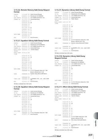

![YAMAHA [PROFESSIONAL AUDIO WORKSTATION]
Model: AW16G
Date: Jan 30, 2002
MIDIMIDI Implementation Chart Version:
Implementation Chart
Function...
1.0
Transmitted
Recognized
Remarks
Basic
Channel
Default
Changed
1–16
1–16
1–16
1–16
Memorized
Memorized
Default
Messages
Altered
X
X
**************
OMNI off/OMNI on
X
X
Memorized
Mode
:True Voice
X
**************
0–127
X
Note
Number
Velocity
Note On
Note Off
X
X
X
X
After
Touch
Key’s
Ch’s
X
X
X
X
X
X
O
O
Assignable
0–127
**************
0–127
0–96
Assignable
O
O
*1
Pitch Bend
Control
Change
Prog
Change
0-95,102-119
:True#
System Exclusive
System
Common
:Song Pos
:Song Sel
:Tune
O
X
X
X
X
X
*2
System
Real Time
:Clock
:Commands
O
O
X
X
*2
*2
Aux
Messages
:Local ON/OFF
:All Notes OFF
:Active Sense
:Reset
X
X
X
X
X
X
O
O
quarter frame message is transmitted.
quarter frame message is recognized.(When MTC Sync mode)
Bulk Dump/Request, MMC
When MCLK Sync mode
MIDI remote, ALL messages canbe transmitted.
Mode 1: OMNI ON, POLY
Mode 3: OMNI OFF, POLY
Mode 2: OMNI ON, MONO
Mode 4: OMNI OFF, MONO
O: Yes
X: No
211
Appendix
Notes
MTC
MTC
*1:
*2:
For](https://image.slidesharecdn.com/aw16ge-131126034127-phpapp02/85/Aw16-ge-211-320.jpg)
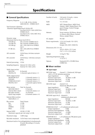
![PHONES
(unbalanced, TRS phone jack)
Nominal load impedance 8–40Ω
Maximum output level
100 mW + 100 mW
(40 Ω load)
DIGITAL STEREO I/O
Optical
* 0 dB= 0.775 Vrms, 0 dBV= 1.0 Vrms
● Digital mixer
Input channel (INPUT 1–8, TRACK 1–16, PAD 1–4)
Attenuator, Phase (normal,
reverse), EQ (4-band PEQ),
Dynamics, On/Off, Pan
Internal effects return
EQ (4-band PEQ), On/Off, Pan
Bus
Stereo L, R
Attenuator, EQ (4-band PEQ),
Dynamics, On/Off, Balance
Bus L, R
Aux 1–2
EFF 1–2
■ Controls
ANALOG SECTION
INPUT [CH1-8] LINE/MIC VR
INPUT [CH1-2] PHANTOM +48V SW ON/OFF
OUTPUT LEVEL MONITOR/PHONES VR
MIXER SECTION
WORK NAVIGATE
SONG/CD/TRACK/EDIT/UTILITY/REMOTE
QUICK NAVIGATE
RECORD/MONITOR
CHANNEL SELECT
INPUT1-8/TRACK 1-8/TRACK
[9/10]-[15/16]/STEREO
MIXER
SCENE/VIEW/[PAN/BAL]/EFF1/
EFF2
EQ
EQ/DYN/HIGH/HI-MID/LO-MID/
LOW
FADER
TRACK 1-8/TRACK [9/10]-[15/16]/
STEREO
SAMPLER SECTION
QUICK LOOP SAMPLER
SELECT/PAD 1-4/EDIT
RECORDER SECTION
LOCATE
/
/IN/OUT/A/B/RTZ/MARK/
SET/CANCEL/AUTO PUNCH/
REPEAT
TRANSPORT
REW/FF/STOP/PLAY/REC
■ Recorder section
● Edit
Song edit
Optimize, Delete, Copy, Import
Track edit
Erase, Delete, Insert, Copy, Move,
Exchange, Time Compression/
Expansion, Pitch Change, Export,
CD import
COMMON SECTION
DATA ENTRY
/ /
/
/ENTER
UNDO/REDO
SOUND CLIP
JOG ON
ENCORDER
DATA/JOG
DISPLAYS
240 × 64 dot GRAPHIC LCD
(contrast control pot.)
Locate
Quick locate: RTZ, A/B, Last REC
In/Out
Mark: 1–99
■ Control I/O
Punch I/O
Manual Punch I/O, Auto Punch I/
O
MIDI IN
5-pin DIN
MIDI OUT/THRU
5-pin DIN
Foot switch
Phone jack
● Others
■ Quick loop sampler
POLYPHONY
RECORDABLE TIME
Edit function
4 voices (stereo)
Total 44 seconds (stereo)
NAME, TRIM, PLAYBACK, MODE,
ERASE, EXTRACT, CD IMPORT,
TRACK IMPORT
Appendix
213](https://image.slidesharecdn.com/aw16ge-131126034127-phpapp02/85/Aw16-ge-213-320.jpg)