Download to read offline
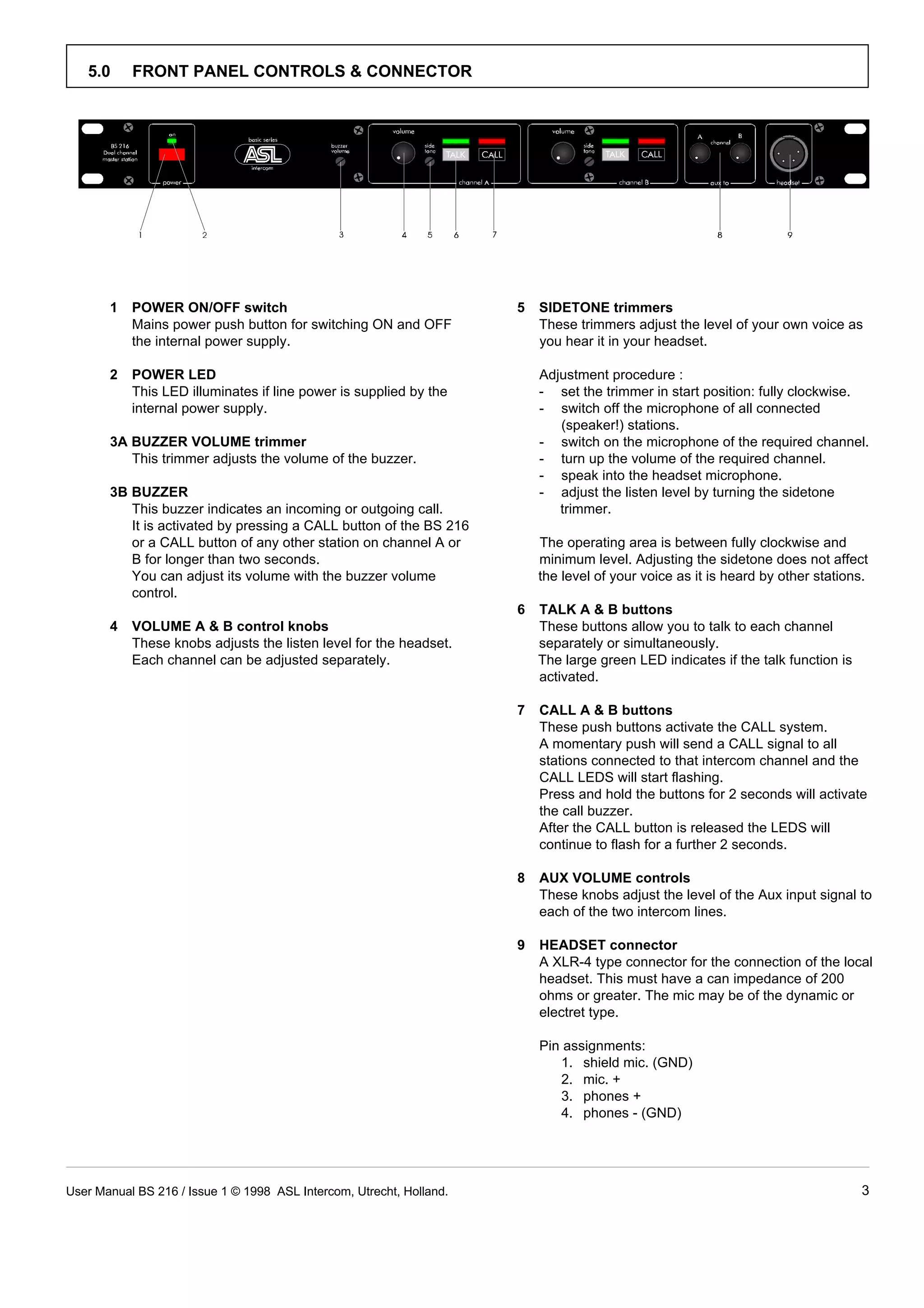
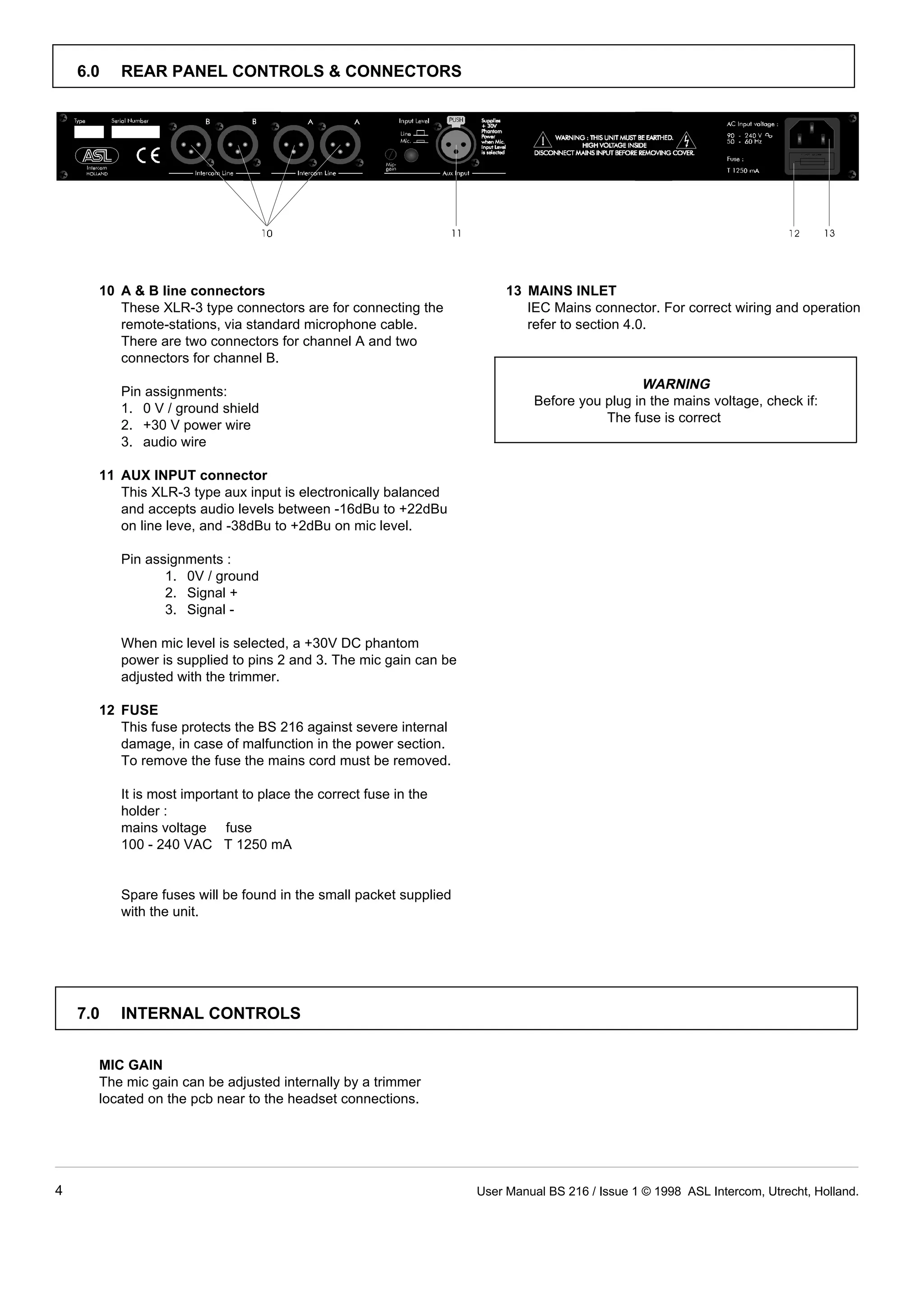
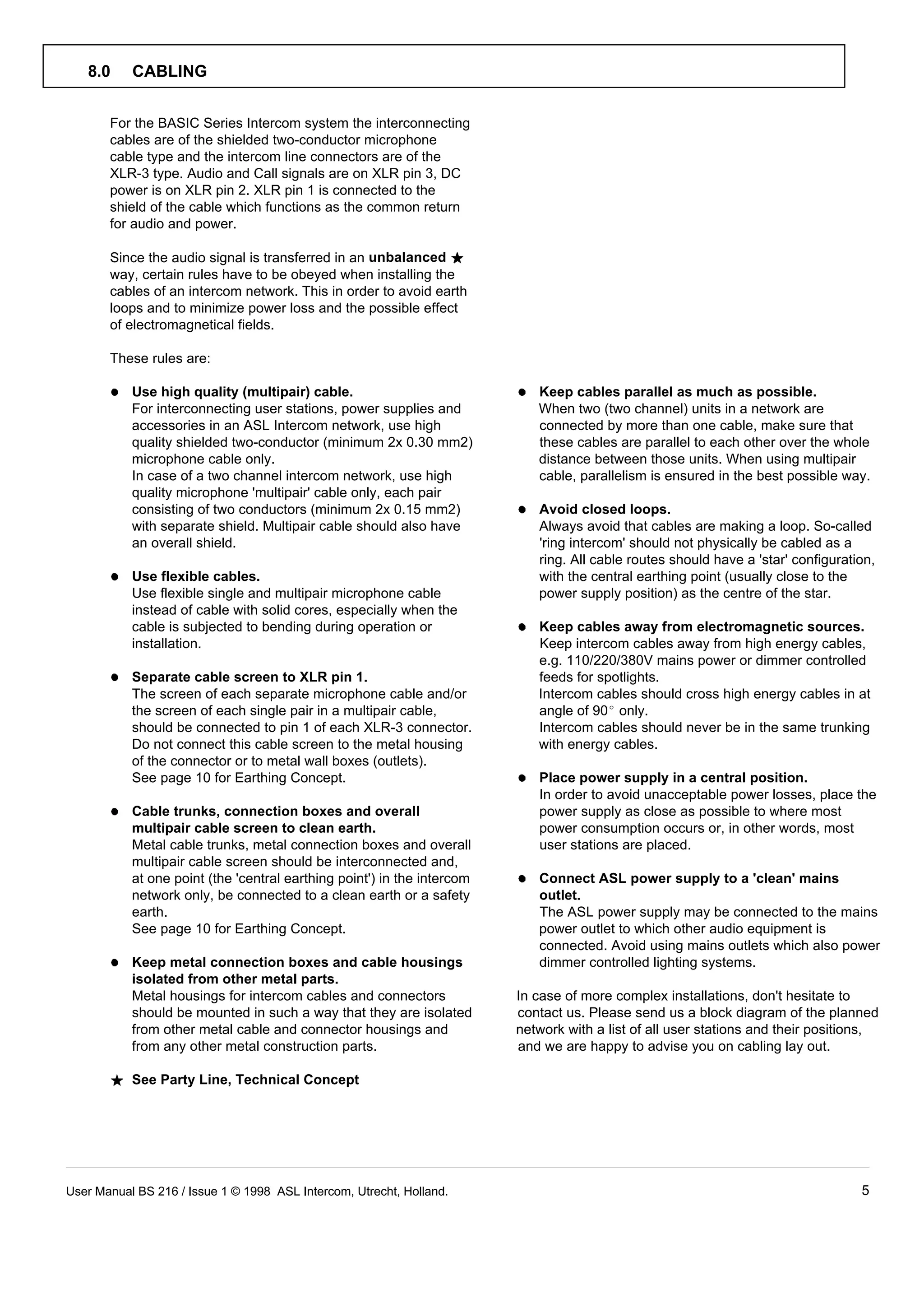
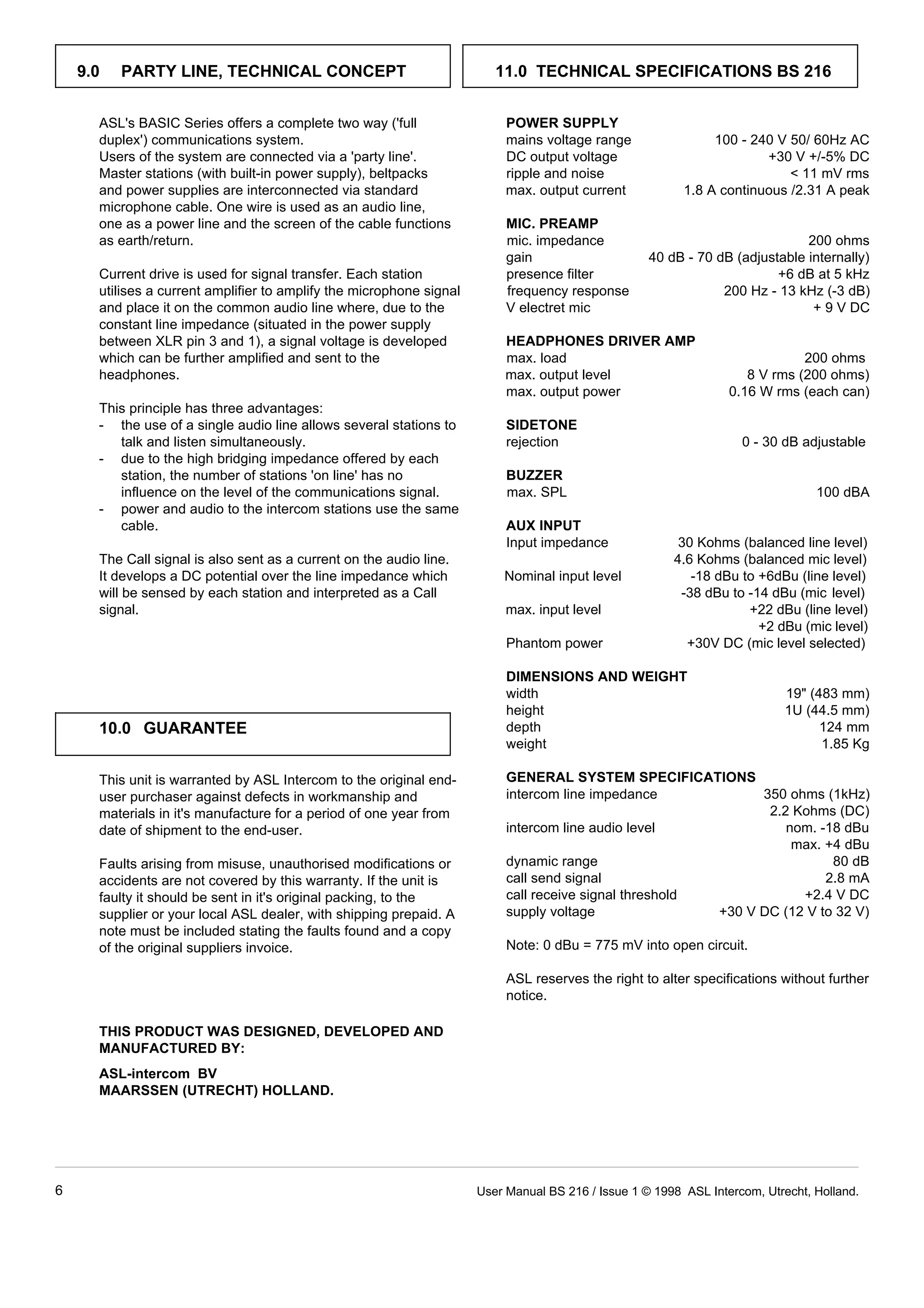
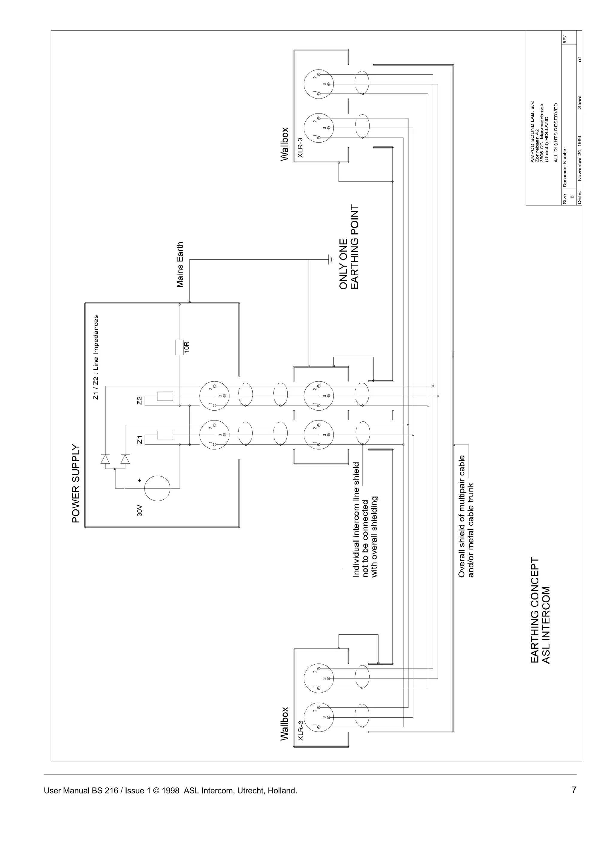
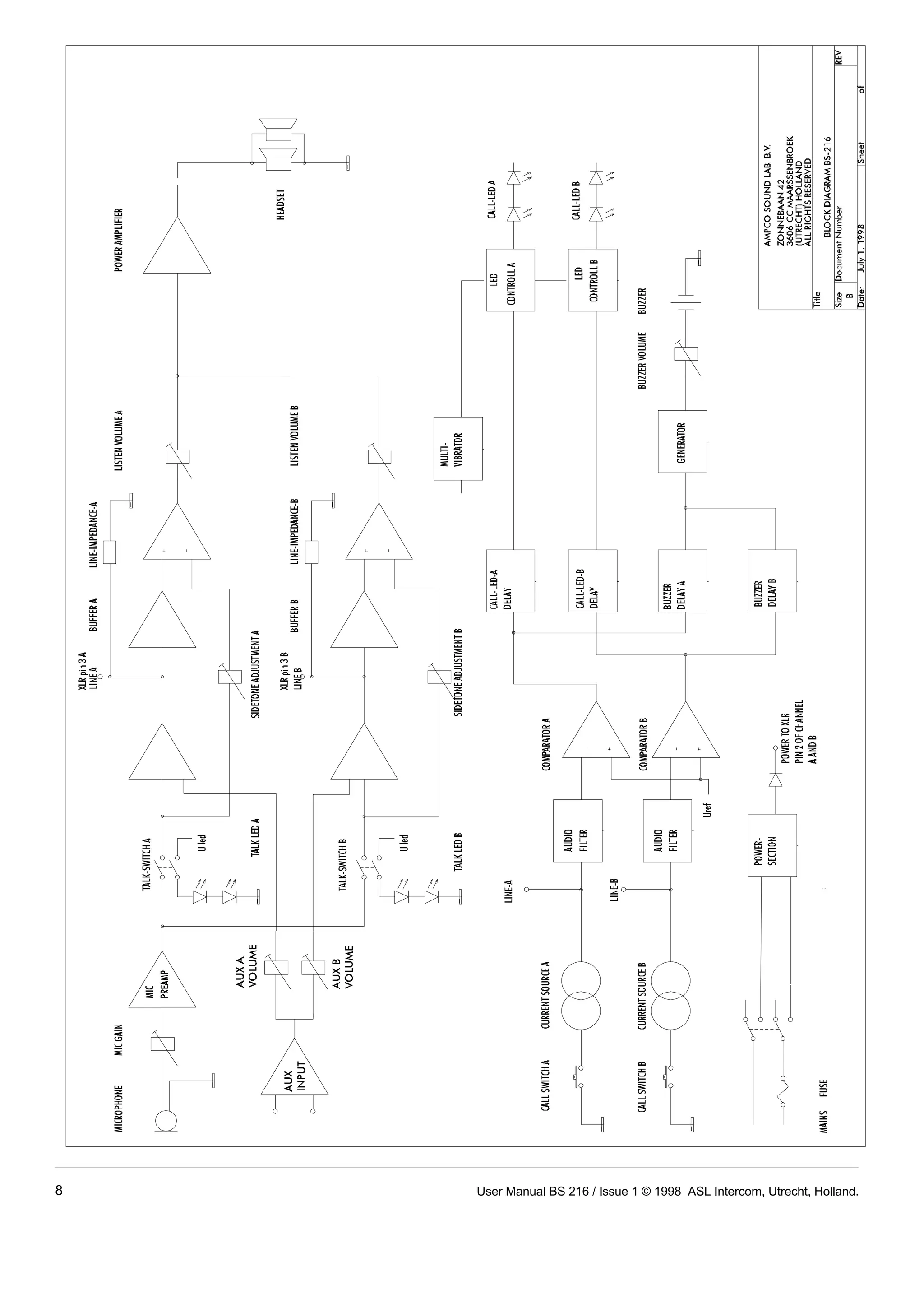
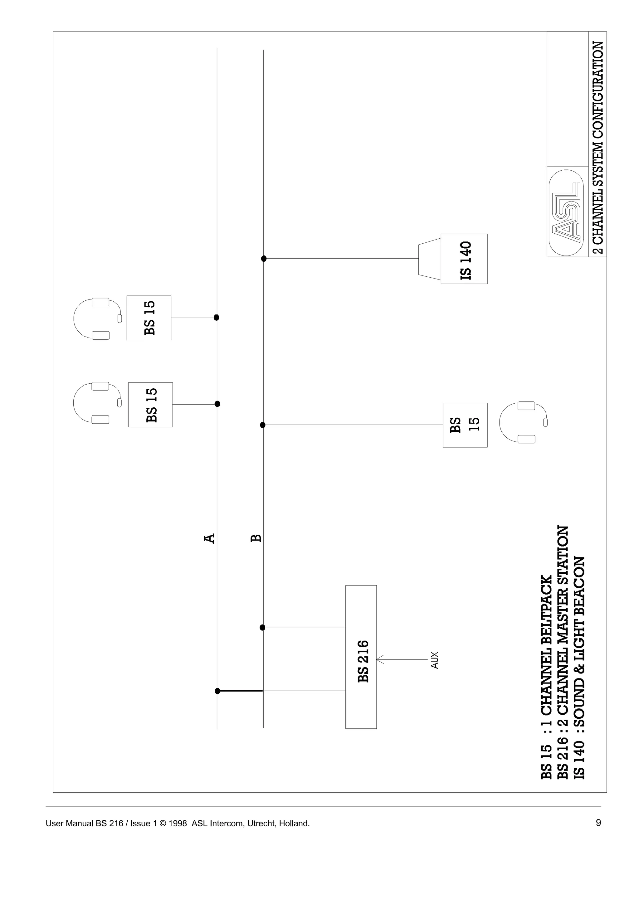


This document is a user manual for the BS 216 dual channel master station. It provides instructions for unpacking, installing, and operating the device. Key features include a dual channel intercom line power supply, auxiliary audio input, and headset station that uses only 1U of rack space. The manual describes front panel controls for volume, talk, call, and sidetone adjustment, as well as rear panel connectors for power, audio lines, and auxiliary input. Cabling guidelines and the technical party line concept are also covered.


