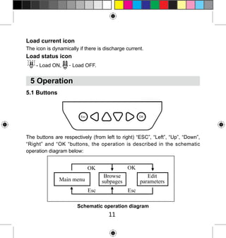
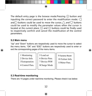
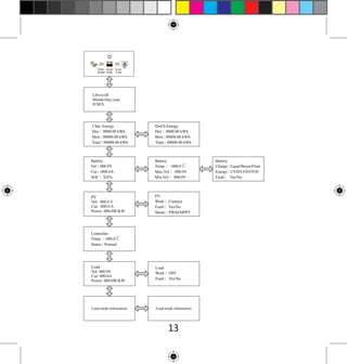
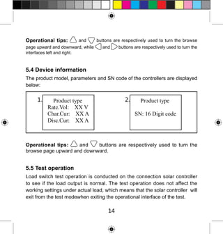
Download to read offline

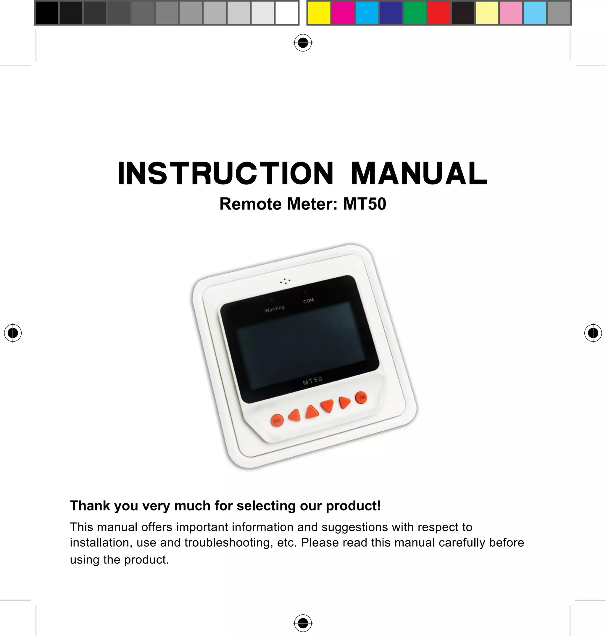
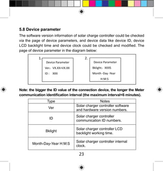

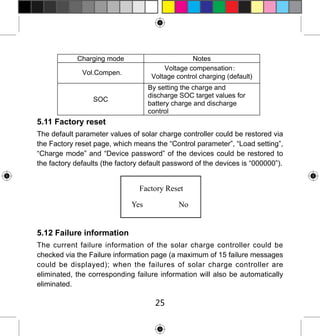
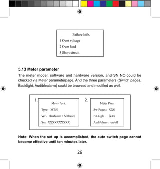
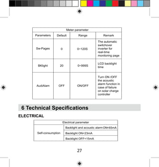
The MT50 remote meter is designed for use with specific solar controllers and provides critical information on installation, usage, and troubleshooting. It features real-time monitoring capabilities, a multifunction LCD display, and robust safety instructions. The manual includes detailed guidelines for installation, operation, and parameter settings, ensuring proper functionality and safety when connecting to designated solar control devices.