
Download to read offline
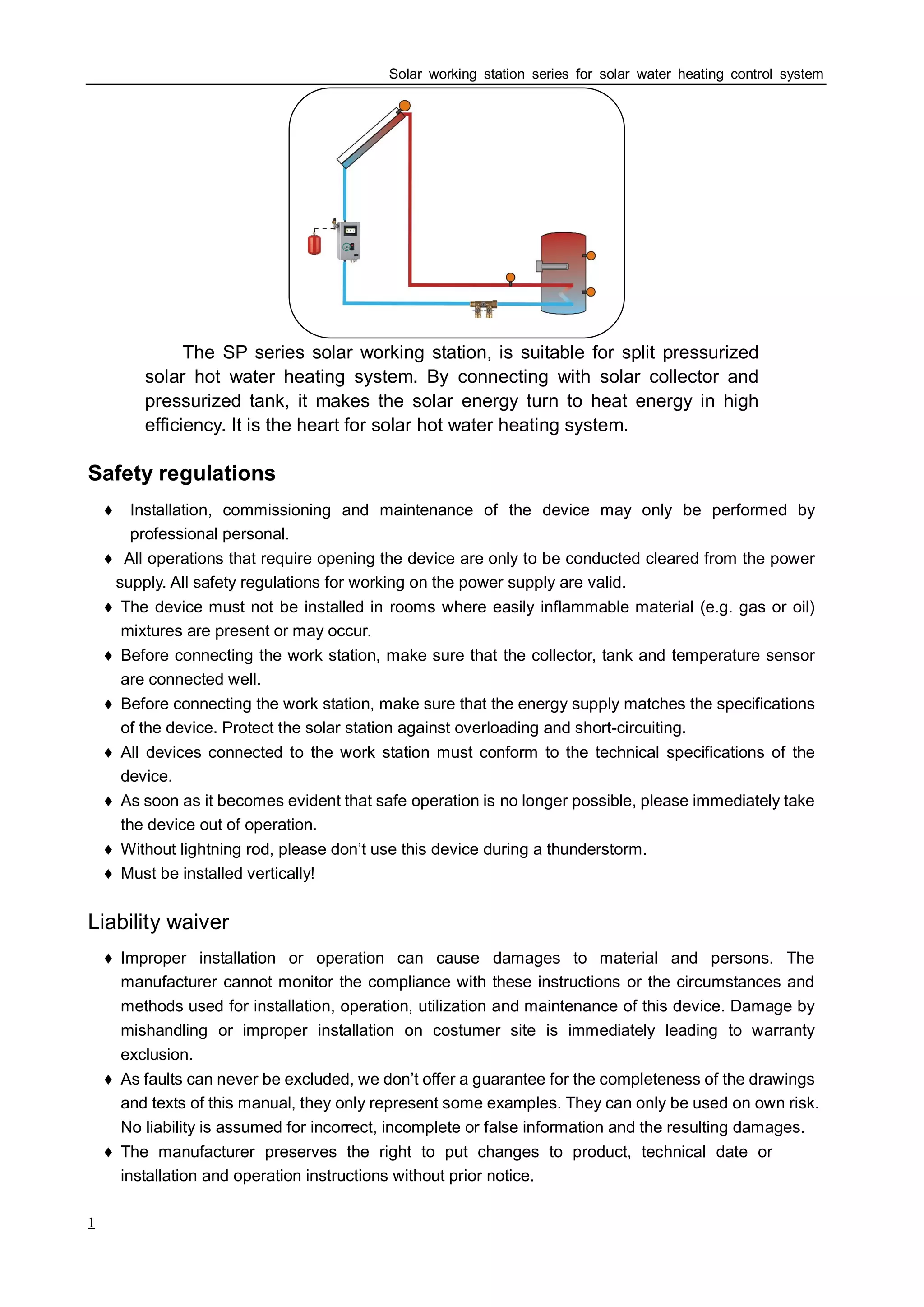
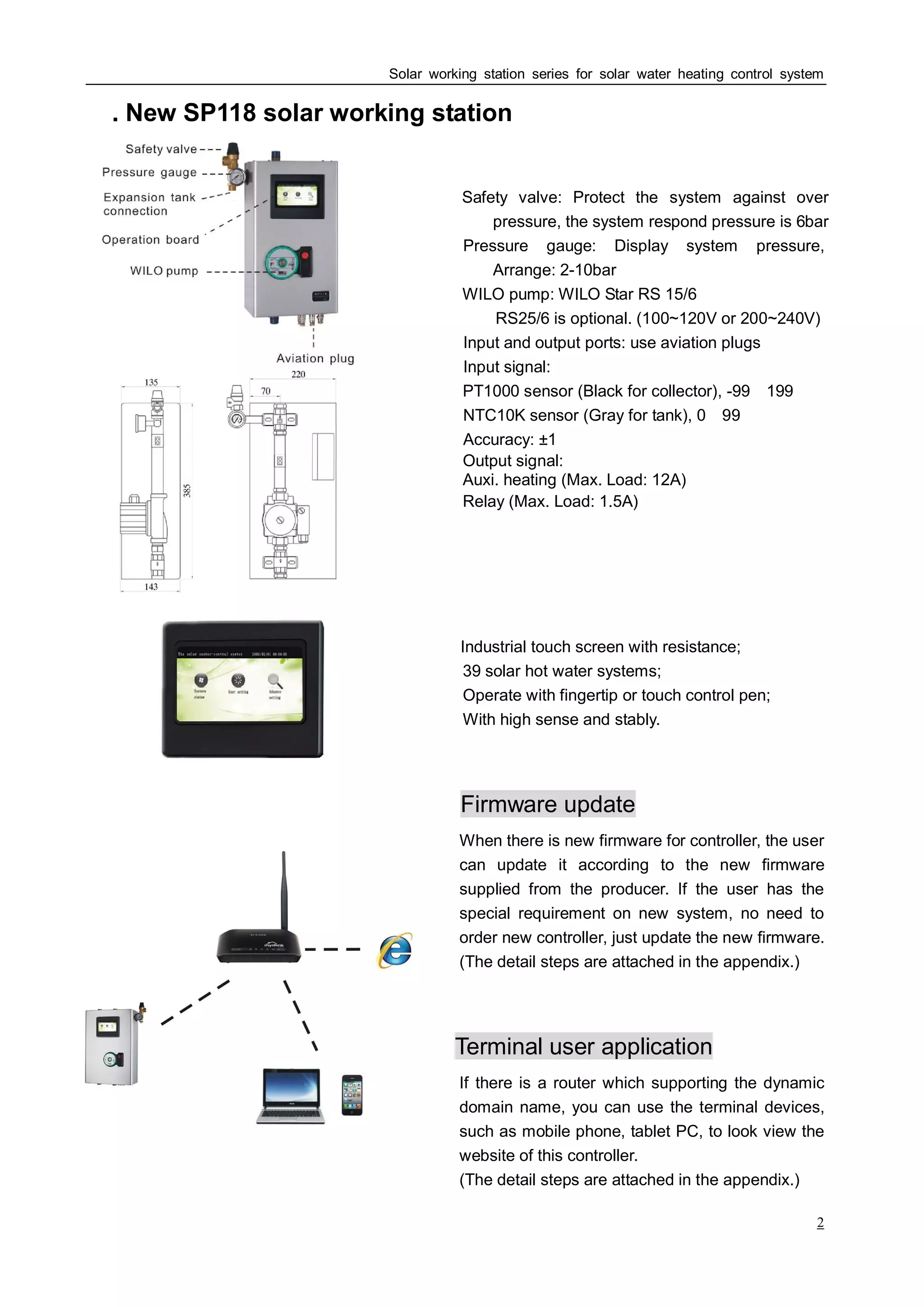
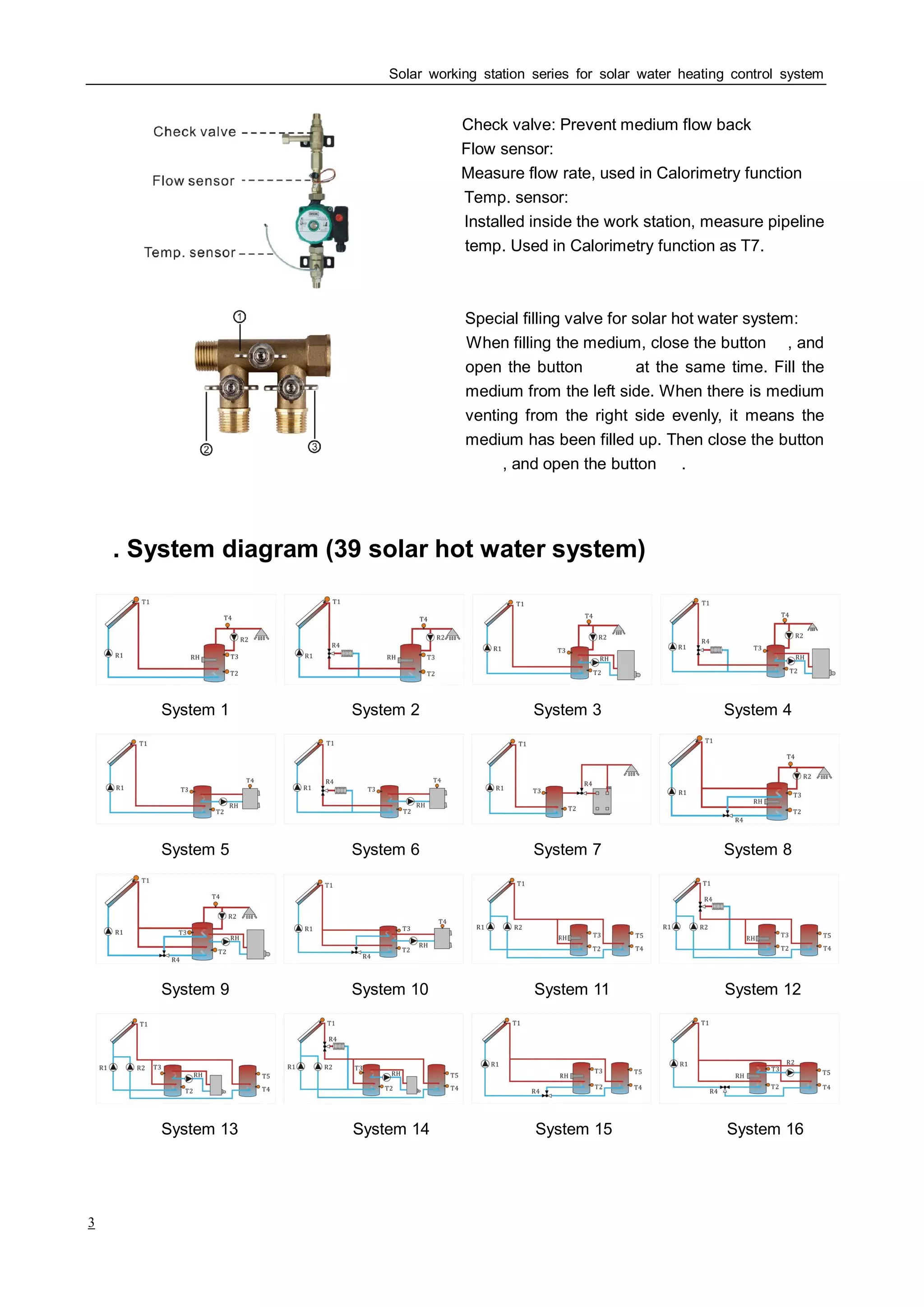
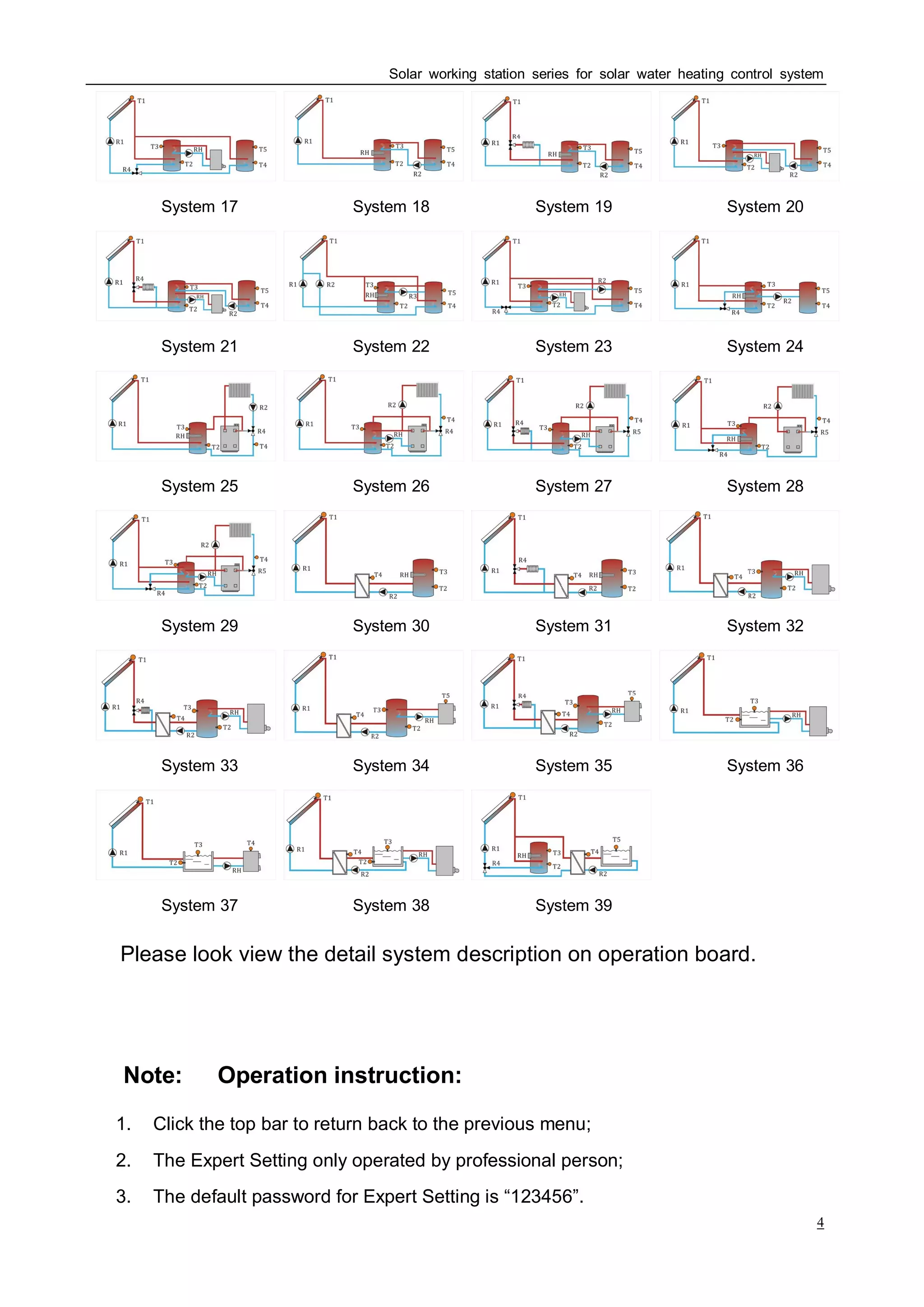
The SP series solar working station controls split-system solar hot water heating systems. It connects the solar collectors and pressurized water tank to efficiently convert solar energy into heat. As the heart of the system, it ensures safety and allows remote monitoring/control via an app. Its touchscreen interface displays operating parameters and system status. The station can integrate up to 39 systems and includes pumps, sensors, and relays to circulate water and trigger auxiliary heating based on temperature thresholds and schedules. Firmware updates allow customizing controls to user needs.


