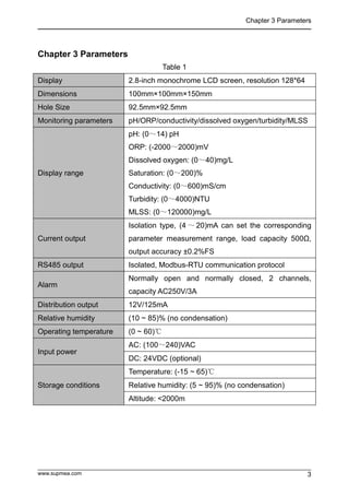
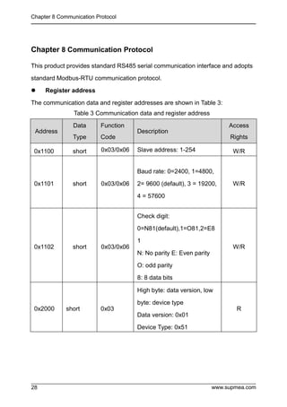
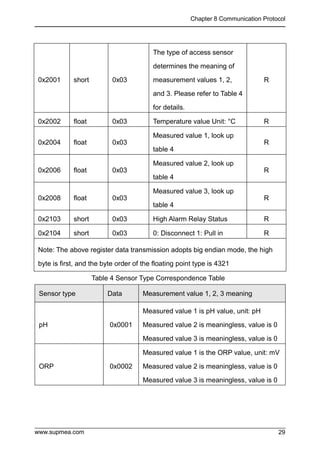
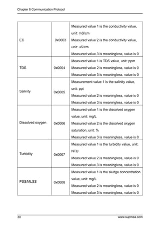
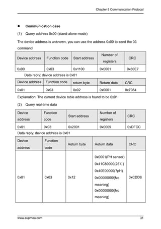
User Manual
U-SUP-DC2000-EN1
Universal controller
Supmea Automation Co.,Ltd.
www.supmea.com
Headquarters
5th floor,Building 4,Singapore Hangzhou Science Technology Park,No. 6 street,
Hangzhou Economic Development Area,Hangzhou 310018,China
Singapore
2 Venture Drive #11-30 Vision Exchange Singapore
info@supmea.com
I
Preface
 Thank you for purchasing our product.
 This manual is an instruction manual about various functions, wiring
methods, setting methods, operation methods, and troubleshooting
methods of the product.
 Please read this manual carefully before operation, use this product
correctly to avoid unnecessary losses due to incorrect operation.
 After you finish reading, please keep it in a place where it can be easily
accessed at any time for reference during operation.
Note
 The contents of this manual are subject to change without notice due to
functional upgrades.
 We strive to be correct in the contents of this manual. If you find any errors,
please contact us.
 The contents of this manual are strictly prohibited to be reproduced or
copied.
 This product is forbidden to be used in explosion-proof occasions.
Version
U-SUP-DC2000-EN1
II
Safety Precautions
In order to use this product safely, be sure to follow the safety precautions
described.
About this manual
 Please submit this manual to the operator for reading.
 Please read the operation manual carefully before applying the instrument.
On the precondition of full understanding.
 This manual only describes the functions of the product. The company does
not guarantee that the product will be suitable for a particular use by the
user.
Precautions for protection, safety and modification of this product
 To ensure safe use of this product and the systems it controls, be sure to
follow the instructions and precautions described in this manual during
operation. Violation of operating procedures may impair the protection
provided by this product. The company does not assume any responsibility
for the quality, performance, function and product safety issues arising from
the above conditions.
 When installing lightning protection devices for this product and its control
system, or designing and installing separate safety protection circuits for
this product and its control system, it needs to be implemented by other
devices.
 If you need to replace parts of the product, please use the model
specifications specified by the company.
 This product is not intended for use in systems that are directly related to
personal safety.Such as nuclear power equipment, equipment using
radioactivity, railway systems, aviation equipment, marine equipment,
aviation equipment and medical equipment.If applied, it is the responsibility
of the user to use additional equipment or systems to ensure personal
safety.
III
 Do not modify this product.The following safety signs are used in this
manual:
 Hazard, if not taken with appropriate precautions, will result in serious
personal injury, product damage or major property damage.
 Warning:Pay special attention to the important information linked to product
or particular part in the operation manual.
 Confirm if the supply voltage is in consistent with the rated voltage
before operation.
 Do not use the instrument in a flammable and combustible or steam
area.
 To prevent from electric shock, operation mistake, a good grounding
protection must be made.
 Thunder prevention engineering facilities must be well managed: the
shared grounding network shall be grounded at is-electric level,
shielded, wires shall be located rationally, SPD surge protector shall be
applied properly.
 Some inner parts may carry high voltage. Do not open the square
panel in the front except our company personnel or maintenance
personnel acknowledged by our company, to avoid electric shock.
 Cut off electric powers before making any checks, to avoid electric
shock.
 Check the condition of the terminal screws regularly. If it is loose,
please tighten it before use.
 It is not allowed to disassemble, process, modify or repair the product
without authorization, otherwise it may cause abnormal operation,
electric shock or fire accident.
 Wipe the product with a dry cotton cloth. Do not use alcohol, benzine
or other organic solvents. Prevent all kinds of liquid from splashing on
the product. If the product falls into the water, please cut off the power
IV

 immediately, otherwise there will be leakage, electric shock or even a
fire accident.
 Please check the grounding protection status regularly. Do not operate
if you think that the protection measures such as grounding protection
and fuses are not perfect.
 Ventilation holes on the product housing must be kept clear to avoid
malfunctions due to high temperatures, abnormal operation, shortened
life and fire.
 Please strictly follow the instructions in this manual, otherwise the
product's protective device may be damaged.
 Do not use the instrument if it is found damaged or deformed at
opening of package.
 Prevent dust, wire end, iron fines or other objects from entering the
instrument during installation, otherwise, it will cause abnormal
movement or failure.
 During operation, to modify configuration, signal output, startup, stop,
operation safety shall be fully considered. Operation mistakes may
lead to failure and even destruction of the instrument and controlled
equipment.
 Each part of the instrument has a certain lifetime, which must be
maintained and repaired on a regular basis for long-time use.
 The product shall be scrapped as industrial wastes, to prevent
environment pollution.
 When not using this product, be sure to turn off the power switch.
 If you find smoke from the product, smell odor, abnormal noise, etc.,
please turn off the power switch immediately and contact the company
in time.
V
Disclaimer
 The company does not make any guarantees for the terms outside the
scope of this product warranty.
 This company is not responsible for damage to the instrument or loss of
parts or unpredictable damage caused directly or indirectly by improper
operation of the user.
Package contents
No Name Quantity Remark
1 Controller 1
2 Butterfly buckle 2 For fixed installation
3 Manual 1
4 Certificate 1
5 Standard Accessories Package 1
After opening the box, please confirm the package contents before starting the
operation.If you find that the model and quantity are incorrect or there is physical
damage in appearance, please contact us.
VI
Content
Chapter 1 Introduction.............................................................................................1
Chapter 2 Features..................................................................................................2
Chapter 3 Parameters............................................................................................. 3
Chapter 4 Fixed installation.....................................................................................4
4.1Instrument installation................................................................................. 4
4.2 Instrument wiring........................................................................................6
Chapter 5 key operation.......................................................................................... 9
5.1 Key distribution...........................................................................................9
5.2 Button Definition .........................................................................................9
Chapter 6 Instrument Interface and Operation......................................................10
6.1 Sensor search interface........................................................................... 10
6.2 Sensor type selection interface................................................................ 10
6.3 Monitoring interface..................................................................................11
6.4 Password verification interface.................................................................12
6.5 Main menu interface.................................................................................13
Chapter 7 Configuration Settings.......................................................................... 14
7.1 System setting interface ...........................................................................14
7.2 Signal setting interface.............................................................................14
7.3 Remote transmission setting interface..................................................... 24
7.4 Alarm setting interface..............................................................................25
7.5 Information query interface.......................................................................27
Chapter 8 Communication Protocol.......................................................................28
Chapter 9 Failure Analysis and Removal.............................................................. 32
Chapter 10 Warranty and After-sale Service......................................................... 33
Chapter 1 Introduction
www.supmea.com 1
Chapter 1 Introduction
This product is a general-purpose controller for water quality, suitable for use with
various water quality series digital sensors of our company. It is used to monitor
water quality parameters including pH, ORP, conductivity, dissolved oxygen,
turbidity, sludge concentration and other water quality parameters. Through RS485
or current transmission output to the monitoring room for record keeping.
Chapter 2 Features
www.supmea.com
2
Chapter 2 Features
 Universal, can match digital sensors such as pH/ORP/Conductivity/Dissolved
oxygen/Turbidity/MLSS.
 Isolated transmission output is adopted, which is less affected by
interference.
 Using isolated RS485 communication technology.
 With high and low alarm output function.
 With sound and light alarm function.
 With LCD backlight switch control function, improve the adaptability of
ambient light.
Chapter 3 Parameters
www.supmea.com 3
Chapter 3 Parameters
Table 1
Display 2.8-inch monochrome LCD screen, resolution 128*64
Dimensions 100mm×100mm×150mm
Hole Size 92.5mm×92.5mm
Monitoring parameters pH/ORP/conductivity/dissolved oxygen/turbidity/MLSS
Display range
pH: (0~14) pH
ORP: (-2000~2000)mV
Dissolved oxygen: (0~40)mg/L
Saturation: (0~200)%
Conductivity: (0~600)mS/cm
Turbidity: (0~4000)NTU
MLSS: (0~120000)mg/L
Current output
Isolation type, (4 ~ 20)mA can set the corresponding
parameter measurement range, load capacity 500Ω,
output accuracy ±0.2%FS
RS485 output Isolated, Modbus-RTU communication protocol
Alarm
Normally open and normally closed, 2 channels,
capacity AC250V/3A
Distribution output 12V/125mA
Relative humidity (10 ~ 85)% (no condensation)
Operating temperature (0 ~ 60)℃
Input power
AC: (100~240)VAC
DC: 24VDC (optional)
Storage conditions
Temperature: (-15 ~ 65)℃
Relative humidity: (5 ~ 95)% (no condensation)
Altitude: <2000m
Chapter 4 Fixed installation
www.supmea.com
4
Chapter 4 Fixed installation
4.1Instrument installation
The installation place and installation method of this product are explained. Please
read this part when installing.
Installation Precautions
 This product is a tray-mounted type.
 Please install it indoors, away from wind, rain and direct sunlight.
 In order to prevent the internal temperature of this product from rising, please
install it in a well-ventilated place.
 Please do not tilt left and right when installing this product, try to install it
horizontally (can be tilted back <30°).
Avoid the following places when installing
 Places directly exposed to sunlight and near hot appliances.
 Places where the ambient temperature exceeds 60°C during operation.
 Places where the ambient humidity exceeds 85% during work.
 Near the source of electromagnetic generation.
 Places with strong mechanical vibration.
 Places where the temperature changes greatly and condensation is easy.
 Places with a lot of oil smoke, steam, moisture, dust and corrosive
gasesInsert the meter into the mounting hole and fasten the butterfly buckle,
as shown in Figure 3:
Chapter 4 Fixed installation
www.supmea.com 5
Figure 3 Schematic diagram of meter installation
Front panel
Butterfly buckle
Chapter 4 Fixed installation
www.supmea.com
6
4.2 Instrument wiring
Figure 4 220VAC wiring diagram
Chapter 4 Fixed installation
www.supmea.com 7
Figure 5 24VDC wiring diagram
Chapter 4 Fixed installation
www.supmea.com
8
Port definition
 +12VDC: 12V positive power supply
 AGND: 12V power supply negative pole
 RS485-A: sensor RS485 communication terminal A
 RS485-B: sensor RS485 communication terminal B
 NC: empty
 485A: RS485 communication terminal A
 485B: RS485 communication terminal B
 I+: (4~20)mA output terminal positive
 I-: (4~20)mA output terminal negative
 HO: High alarm normally open relay
 HC: High alarm normally closed relay
 COM: relay common terminal
 LO: Low alarm normally open relay
 LC: Low alarm normally closed relay
 COM: relay common terminal
 L: Power port L
 NC: empty
 N: Power port N
 24V+: Positive pole of 24V power supply
 24V-: 24V power supply negative
Notice
 To prevent electric shock, please confirm that the meter is not powered on
before connecting the signal cable.
 To prevent fire, please use double insulated wire.
 Please do not place live products close to the signal terminals, which may
cause malfunction.
Chapter 5 Key operation
www.supmea.com 9
Chapter 5 Key operation
5.1 Key distribution
Figure 6 Button distribution diagram
5.2 Button Definition
Table 2
Identifier Key Name Function Description
Escape key
View related alarm status under "Monitoring Interface"
Return to the upper layer between the relevant upper and
lower layers of the interface under the "menu interface"
Right shift Modified bits of the cycle selection parameter
Menu
Enter the menu under "Monitoring Interface"
Exit menu under "Menu interface"
Downshift
Select the relevant menu under "Menu interface"
Modify the relevant value in the setting state
Enter
Enter the submenu under "Menu interface" or confirm the
modification
Chapter 6 Instrument Interface and Operation
www.supmea.com
10
Chapter 6 Instrument Interface and Operation
6.1 Sensor search interface
When the meter is powered on, it will automatically match some sensors. If the
matching is successful, it will automatically enter the meter monitoring interface. If
the match is not successful, enter the sensor type selection interface.
Figure 7
6.2 Sensor type selection interface
pH/ORP: Optional digital sensor model pH-8001
Turbidity: optional digital sensor model PTU-8010/PTU-8011
PSS: optional digital sensor model PSS-9011
Dissolved Oxygen: Optional digital sensor model
DO-7010/DO-7012/DO-7013/DO-7016
Conductivity: optional digital sensor model TDS-8001
Figure 8
1. PH/ORP
2. Tubur
3. MLss
4. DO
5. TDS
Sensor Type
Sensor Type
Chapter 6 Instrument Interface and Operation
www.supmea.com 11
6.3 Monitoring interface
The interface displays "Sensor not connected", indicating that the connection
between the meter and the sensor is faulty. It is necessary to check whether the
meter wiring and electrode type selection are correct. If the sensor type is
incorrectly selected, long press to re-enter the sensor type selection interface.
Figure 9
Use to enter the password verification interface, enter the password to enter
the main menu interface.
Use to enter the alarm query interface to query the current alarm setting
information.
Note: XX automatically switches the measurement parameter type according to
the selected sensor.
Figure 10 pH monitoring interface Figure 11 ORP monitoring interface
Chapter 6 Instrument Interface and Operation
www.supmea.com
12
Figure 12 Conductivity monitoring interface Figure 13 DO monitoring interface
Figure 14 Turbidity monitoring interface Figure 15 MLSS monitoring interface
Note: If the instrument is not operated for 3 minutes, it will automatically jump to
the monitoring interface.
6.4 Password verification interface
After entering the password, use it to enter the main menu interface.
The initial password is "0000", you can use the password modification function to
modify the password.
If you forget your password, please contact our company.
Figure 16
DO
25.0℃ 20.00mA
0.05mg/L
99%
User Password
Chapter 6 Instrument Interface and Operation
www.supmea.com 13
6.5 Main menu interface
System Settings: Language,Buzzer,Backlight,Change Password and Factory
Setting
Signal Settings: Sensor parameters, Calibration, Revision and other function
settings.
Remote setting: Communication Settings, Electrorheological send
Alarm setting: parameter setting of high alarm and low alarm.
Information inquiry: current version information query.
Figure 17
--Main Menu--
1 .Systeming Setting
2 .Signal Setting
3 .Remote Setting
4 .Alarm Setting
5.Information Inquiry
Chapter 7 Configuration Settings
www.supmea.com
14
Chapter 7 Configuration Settings
7.1 System setting interface
Language: Set the type of language, Chinese and English can be set.
Buzzer: Set the buzzer switch when alarming.
Backlight Setting: Set the switch of LCD backlight.
Change Password: Change the password and log in with the new password.
Factory Settings: Restore factory settings.
Figure 18
7.2 Signal setting interface
7.2.1 pH signal setting
7.2.1.1 Online calibration:
① Wash the sensor with distilled water, wipe off the water stains, and then put it in
the calibration solution;
②Select the calibration point according to the calibration solution. The
corresponding values of the NIST calibration points from small to large are 4.00
pH, 6.86 pH and 9.18 pH respectively (the corresponding values from small to
large in USA are 4.01 pH, 7.00 pH and 10.01 pH respectively). After entering the
calibration interface, Wait for a while, and after the measured value is stable, use
the to complete the calibration.
--Systeming setting--
1.Language
2.Buzzer
3.Backlight
4.Change Password
5.Factory setting
Chapter 7 Configuration Settings
www.supmea.com 15
Figure 19
7.2.1.2 Signal correction:
The measured pH value can be corrected.
Figure 20
7.2.1.3 Measurement parameters:
Select the sensor to measure the primary parameter pH or ORP.
Figure 21
--Signal Setting--
1.Online Calibration
2.Signal Correction
3.Measure Param
--Signal Correction--
--Signal Setting--
1.Online Calibration
2.Signal Correction
3.Measure Param
--Measure Param--
1.pH
2.ORP
Chapter 7 Configuration Settings
www.supmea.com
16
7.2.2 ORP Signal Settings
7.2.2.1 Online calibration:
After entering the online calibration interface, enter the standard solution value,
put the sensor into the standard solution, wait for a while, and use the to
complete the calibration after the measured value is stable. Before calibration, the
sensor needs to be washed with distilled water and wiped dry. After soaking in
water, put it in the calibration solution for calibration
Figure 22
7.2.2.2 Signal correction:
The measured ORP value can be corrected.
Figure 23
--Signal Setting--
1.Online Calibration
2.Signal Correction
3.Measure Param
--Signal Correction--
Chapter 7 Configuration Settings
www.supmea.com 17
7.2.3 Turbidity Signal Settings
7.2.3.1 Turbidity factor:
Parameter settings for turbidity factor.
Figure 24
7.2.3.2 Signal Revision:
The measured turbidity value can be corrected.
Figure 25
7.2.3.3 Wiping Time:
Set the sensor wipe time interval (1min, 5min, 15min, 30min, 1h, 4h, 12h, 1d, 3d,
7d).
Figure 26
--Signal Setting--
1.Tu Factor
2.Signal Correction
3.Wiping Time
--Tu Factor--
--Signal Setting--
1.Tu Factor
2.Signal Correction
3.Wiping Time
--Signal Correction--
--Signal Setting--
1.Tu Factor
2.Signal Correction
3.Wiping Time
--Wiping Time--
Chapter 7 Configuration Settings
www.supmea.com
18
7.2.4 Sludge concentration signal setting
7.2.4.1 Online calibration:
Calibrate the sensor. The sludge concentration sensor has been calibrated before
leaving the factory. If you need to calibrate yourself, you can follow the steps below.
Sludge concentration calibration requires the use of standard solutions. The
specific steps are as follows:
In the signal setting, set the sludge concentration factor to 1, enter the first point
calibration interface of sludge concentration and wipe the sensor probe;
Put the probe into the first point of standard solution (usually pure water is used as
the first point), input the standard value of the first point of standard solution and
click, after the measured value data is stable, click to complete the
first point calibration;
Take the probe out of the first standard solution, rinse with clean water, and dry the
sensor.
Put the probe into the second-point standard solution, input the standard value of
the second-point standard solution, and click. After the measured value
data is stable, click to complete the second-point calibration.
Figure 27
Chapter 7 Configuration Settings
www.supmea.com 19
7.2.4.2 Signal correction:
The measured sludge concentration value can be corrected.
Figure 28
7.2.4.3 Sludge concentration factor:
Parameter setting of sludge concentration factor.
Figure 29
7.2.4.4 Wiping Time
Set the sensor wipe time interval (1min, 5min, 15min, 30min, 1h, 4h, 12h, 1d, 3d,
7d).
Figure 30
--Signal Setting--
1.Online Calibration
2.Signal Correction
3.SS Factor
--Signal Correction--
--Signal Setting--
1.Online Calibration
2.Signal Correction
3.SS Factor
--Signal Setting--
2.Signal Correction
3.SS Factor
4.Wiping Time
--Wiping Time--
--SS Factor--
Chapter 7 Configuration Settings
www.supmea.com
20
7.2.5 Dissolved oxygen signal setting
7.2.5.1 Online calibration:
Zero oxygen and air calibration can be selected. The first point of the calibration
point corresponds to zero oxygen calibration, which can be calibrated in
anhydrous sodium sulfite solution (configured with deionized water), and the
second point corresponds to air calibration, which can be in air or saturated air and
water To calibrate, after entering the calibration interface, you need to wait for a
while, and after the measured value is stable, use to complete the calibration.
Figure 31
7.2.5.2 Signal Revision
The measured dissolved oxygen value can be corrected.
Figure 32
--Signal Setting--
1.Online Calibration
2.Signal Correction
3.Salinity Setting
--Signal Correction--
Chapter 7 Configuration Settings
www.supmea.com 21
7.2.5.3 Salinity setting:
Sets the salinity value of the current solution. The default value is 0.00ppt.
Figure 33
7.2.5.4 The Pressure setting:
Sets the barometric pressure value at the current altitude. The default is 1standard
atmosphere(760mmHg).
Figure 34
7.2.6 Conductivity Signal Settings
7.2.6.1 Online calibration:
You can perform single-point calibration of any standard solution, enter the
conductivity calibration input interface, and enter the calibration solution value to
be calibrated (common standard solutions are 147.0μS/cm, 1413μS/cm and
12.88mS/cm, the actual can be calibrated according to on-site standards ),Press
to enter the conductivity calibration interface, and then put the connected
electrode into the standard solution. After the reading is stable, press the
--Signal Setting--
1.Online Calibration
2.Signal Correction
3.Salinity Setting
--Salinity Setting--
--Signal Setting--
2.Signal Correction
3.Salinity Setting
4.Atm.Pressure
--Atm.Pressure--
Chapter 7 Configuration Settings
www.supmea.com
22
calibration button.
Figure 35
7.2.6.2 Signal correction:
The measured conductivity value can be corrected.
Figure 36
7.2.6.3 Electrode constant:
Set the sensor cell constant.
Figure 37
--Signal Setting--
1.Online Calibration
2.Signal Correction
3.Electrode Constant
--Signal Correction--
--Signal Setting--
1.Online Calibration
2.Signal Correction
3.Electrode Constant
--Electrode Constant--
Chapter 7 Configuration Settings
www.supmea.com 23
7.2.6.4 Temperature compensation coefficient:
Set the temperature compensation coefficient of the solution, the default is 2.00%.
Figure 38
7.2.6.5 TDS coefficient:
Set the conversion factor for conductivity and total dissolved solids.
Figure 39
7.2.6.6 Measurement parameters:
Select the sensor to measure the main parameter.
Figure 40
--Signal Setting--
2.Signal Correction
3.Electrode Constant
4.Temp Coefficient
--Temp Coefficient--
--Signal Setting--
3.Electrode Constant
4.Temp Coefficient
5.TDS Coefficient
--TDS Coefficient--
--Signal Setting--
4.Temp Coefficient
5.TDS Coefficient
6.Measure Param
--Measurement Param--
1.EC
2.TDS
3.Salinity
Chapter 7 Configuration Settings
www.supmea.com
24
7.3 Remote transmission setting interface
7.3.1 Communication settings:
Set the address, baud rate and parity bit of 485 communication.
:Select address digits, baud rate, check digit
:Optional. Address range (1~254), optional baud rate (2400, 4800, 9600,
19200, 57600), optional check bit (no check, odd check, even check)
:save setting parameters
:Back to monitoring interface
:Return to the remote transmission setting interface
Figure 41
7.3.2 Current transmission:
The engineering value corresponding to 4mA and the engineering value
corresponding to 20mA of (4~20) mA output can be set.
:select the number of digits to set the parameter data
:change data size
:Jump to 20mA parameter setting, save the setting parameters
:Return to the monitoring interface
:Return to 4mA parameter setting, return to remote transmission setting
interface
Note: The unit xx and the data size are automatically switched according to the
selected sensor
--Remote Setting--
1.Comm
2.Current Transmission
--Comm--
Address:
Baud Rate:
Parity Bit: No check
Chapter 7 Configuration Settings
www.supmea.com 25
Figure 42
7.4 Alarm setting interface
7.4.1 High report settings:
Set the alarm value and hysteresis difference of the high alarm relay. When
(measured value > alarm value), the normally open contact of the high alarm relay
is closed, and the normally closed contact is disconnected. When (measured
value < alarm value - hysteresis) , the normally open contact of the high report
relay is disconnected, and the normally closed contact is closed.
:Select to set parameter data digits
:Change data size
:Jump to hysteresis parameter setting, save the setting parameters
:Back to monitoring interface
:
Return to the alarm value parameter setting, return to the alarm setting
interface
Note: The unit xx and the data size are automatically switched according to the
selected sensor
Figure 43
--Alarm Setting--
1.High Alarm
2.Low Alarm
--High Alarm--
Value
Hysteresis
--Remote Setting--
1. Comm
2. Current Transmission
--Current Transmission--
--
Chapter 7 Configuration Settings
www.supmea.com
26
7.4.2 Low report settings:
Set the alarm value and hysteresis value of the low alarm relay. When (measured
value < alarm value), the normally open contact of the low alarm relay is closed,
and the normally closed contact is disconnected. When (measured value > alarm
value + hysteresis) When the low alarm relay normally open contact is
disconnected, the normally closed contact is closed
.:Select to set parameter data digits
:Change data size
:Jump to hysteresis parameter setting, save the setting parameters
:Back to monitoring interface
:Return to the alarm value parameter setting, return to the alarm setting
interface
Note: The unit xx and the data size are automatically switched according to the
selected sensor
Figure 44
--Alarm Setting--
1.High Alarm
2.Low Alarm
--Low Alarm --
Value
Hysteresis
Chapter 7 Configuration Settings
www.supmea.com 27
7.5 Information query interface
Version Information:
Query the current software version.
Figure 45
--Information Inquiry--
1.Version Information
Chapter 8 Communication Protocol
www.supmea.com
28
Chapter 8 Communication Protocol
This product provides standard RS485 serial communication interface and adopts
standard Modbus-RTU communication protocol.
 Register address
The communication data and register addresses are shown in Table 3:
Table 3 Communication data and register address
Address
Data
Type
Function
Code
Description
Access
Rights
0x1100 short 0x03/0x06 Slave address: 1-254 W/R
0x1101 short 0x03/0x06
Baud rate: 0=2400, 1=4800,
2= 9600 (default), 3 = 19200,
4 = 57600
W/R
0x1102 short 0x03/0x06
Check digit:
0=N81(default),1=O81,2=E8
1
N: No parity E: Even parity
O: odd parity
8: 8 data bits
W/R
0x2000 short 0x03
High byte: data version, low
byte: device type
Data version: 0x01
Device Type: 0x51
R
Chapter 8 Communication Protocol
www.supmea.com 29
0x2001 short 0x03
The type of access sensor
determines the meaning of
measurement values 1, 2,
and 3. Please refer to Table 4
for details.
R
0x2002 float 0x03 Temperature value Unit: °C R
0x2004 float 0x03
Measured value 1, look up
table 4
R
0x2006 float 0x03
Measured value 2, look up
table 4
R
0x2008 float 0x03
Measured value 3, look up
table 4
R
0x2103 short 0x03 High Alarm Relay Status R
0x2104 short 0x03 0: Disconnect 1: Pull in R
Note: The above register data transmission adopts big endian mode, the high
byte is first, and the byte order of the floating point type is 4321
Table 4 Sensor Type Correspondence Table
Sensor type Data Measurement value 1, 2, 3 meaning
pH 0x0001
Measured value 1 is pH value, unit: pH
Measured value 2 is meaningless, value is 0
Measured value 3 is meaningless, value is 0
ORP 0x0002
Measured value 1 is the ORP value, unit: mV
Measured value 2 is meaningless, value is 0
Measured value 3 is meaningless, value is 0
Chapter 8 Communication Protocol
www.supmea.com
30
EC 0x0003
Measured value 1 is the conductivity value,
unit: mS/cm
Measured value 2 is the conductivity value,
unit: uS/cm
Measured value 3 is meaningless, value is 0
TDS 0x0004
Measured value 1 is TDS value, unit: ppm
Measured value 2 is meaningless, value is 0
Measured value 3 is meaningless, value is 0
Salinity 0x0005
Measurement value 1 is the salinity value,
unit: ppt
Measured value 2 is meaningless, value is 0
Measured value 3 is meaningless, value is 0
Dissolved oxygen 0x0006
Measured value 1 is the dissolved oxygen
value, unit: mg/L
Measured value 2 is the dissolved oxygen
saturation, unit: %
Measured value 3 is meaningless, value is 0
Turbidity 0x0007
Measured value 1 is the turbidity value, unit:
NTU
Measured value 2 is meaningless, value is 0
Measured value 3 is meaningless, value is 0
PSS/MLSS 0x0008
Measured value 1 is the sludge concentration
value, unit: mg/L
Measured value 2 is meaningless, value is 0
Measured value 3 is meaningless, value is 0
Chapter 8 Communication Protocol
www.supmea.com 31
 Communication case
(1) Query address 0x00 (stand-alone mode)
The device address is unknown, you can use the address 0x00 to send the 03
command
Device address Function code Start address
Number of
registers
CRC
0x00 0x03 0x1100 0x0001 0x80E7
Data reply: device address is 0x01
Device address Function code return byte Return data CRC
0x01 0x03 0x02 0x0001 0x7984
Explanation: The current device table address is found to be 0x01
(2) Query real-time data
Device
address
Function
code
Start address
Number of
registers
CRC
0x01 0x03 0x2001 0x0009 0xDFCC
Data reply: device address is 0x01
Device
address
Function
code
Return byte Return data CRC
0x01 0x03 0x12
0x0001(PH sensor)
0x41C80000(25℃)
0x40E00000(7pH)
0x00000000(No
meaning)
0x00000000(No
meaning)
0xCDD8
Chapter 9 Failure Analysis and Removal
www.supmea.com
32
Chapter 9 Failure Analysis and Removal
Question 1: No display on the controller?
Answer: Make sure that the power supply wiring is correct and the power supply
can supply power normally.
Question 2: The controller display numbers jump up and down?
A: Check whether there are any interference devices such as inverters around, and
pay attention to stay away from these interference devices or take shielding
measures.
Q3: The controller cannot be calibrated?
Answer: The standard solution is not prepared correctly or the electrode is
damaged.
Question 4: The display area of the screen is that the sensor is not connected?
A: Confirm whether the sensor is disconnected.
Q5: Wrong sensor selection?
A: You can press and hold to re-enter the sensor selection interface and
select the correct sensor.
Chapter 10 Warranty and After-sale Service
www.supmea.com 33
33
Chapter 10 Warranty and After-sale Service
We promise to the customer that the hardware accessories provided during the
supply of the instrument have no defects in material and manufacturing process.
From the date of the purchase, if the user's notice of such defects is received
during the warranty period, the company will unconditionally maintain or replace
the defective products without charge, and all non customized products are
guaranteed to be returned and replaced within 7 days.
Disclaimers:
 During the warranty period, product faults caused by the following reasons
are not in the scope of Three Guarantees service
 Product faults caused by improper use by customers.
 Product faults caused by disassembling, repairing and refitting the product.
After-sales service commitment:
 We promise to deal with the customer's technical questions within 2 hours.
 For the instruments returned to the factory for maintenance, we promise to
issue the test results within 3 working days and the maintenance results
within 7 working days after receiving them.

sup-dc2000-digital-analyzer-monitor-user-manual.pdf

  • 1.
    User Manual U-SUP-DC2000-EN1 Universal controller SupmeaAutomation Co.,Ltd. www.supmea.com Headquarters 5th floor,Building 4,Singapore Hangzhou Science Technology Park,No. 6 street, Hangzhou Economic Development Area,Hangzhou 310018,China Singapore 2 Venture Drive #11-30 Vision Exchange Singapore info@supmea.com
  • 2.
    I Preface  Thank youfor purchasing our product.  This manual is an instruction manual about various functions, wiring methods, setting methods, operation methods, and troubleshooting methods of the product.  Please read this manual carefully before operation, use this product correctly to avoid unnecessary losses due to incorrect operation.  After you finish reading, please keep it in a place where it can be easily accessed at any time for reference during operation. Note  The contents of this manual are subject to change without notice due to functional upgrades.  We strive to be correct in the contents of this manual. If you find any errors, please contact us.  The contents of this manual are strictly prohibited to be reproduced or copied.  This product is forbidden to be used in explosion-proof occasions. Version U-SUP-DC2000-EN1
  • 3.
    II Safety Precautions In orderto use this product safely, be sure to follow the safety precautions described. About this manual  Please submit this manual to the operator for reading.  Please read the operation manual carefully before applying the instrument. On the precondition of full understanding.  This manual only describes the functions of the product. The company does not guarantee that the product will be suitable for a particular use by the user. Precautions for protection, safety and modification of this product  To ensure safe use of this product and the systems it controls, be sure to follow the instructions and precautions described in this manual during operation. Violation of operating procedures may impair the protection provided by this product. The company does not assume any responsibility for the quality, performance, function and product safety issues arising from the above conditions.  When installing lightning protection devices for this product and its control system, or designing and installing separate safety protection circuits for this product and its control system, it needs to be implemented by other devices.  If you need to replace parts of the product, please use the model specifications specified by the company.  This product is not intended for use in systems that are directly related to personal safety.Such as nuclear power equipment, equipment using radioactivity, railway systems, aviation equipment, marine equipment, aviation equipment and medical equipment.If applied, it is the responsibility of the user to use additional equipment or systems to ensure personal safety.
  • 4.
    III  Do notmodify this product.The following safety signs are used in this manual:  Hazard, if not taken with appropriate precautions, will result in serious personal injury, product damage or major property damage.  Warning:Pay special attention to the important information linked to product or particular part in the operation manual.  Confirm if the supply voltage is in consistent with the rated voltage before operation.  Do not use the instrument in a flammable and combustible or steam area.  To prevent from electric shock, operation mistake, a good grounding protection must be made.  Thunder prevention engineering facilities must be well managed: the shared grounding network shall be grounded at is-electric level, shielded, wires shall be located rationally, SPD surge protector shall be applied properly.  Some inner parts may carry high voltage. Do not open the square panel in the front except our company personnel or maintenance personnel acknowledged by our company, to avoid electric shock.  Cut off electric powers before making any checks, to avoid electric shock.  Check the condition of the terminal screws regularly. If it is loose, please tighten it before use.  It is not allowed to disassemble, process, modify or repair the product without authorization, otherwise it may cause abnormal operation, electric shock or fire accident.  Wipe the product with a dry cotton cloth. Do not use alcohol, benzine or other organic solvents. Prevent all kinds of liquid from splashing on the product. If the product falls into the water, please cut off the power
  • 5.
    IV   immediately, otherwisethere will be leakage, electric shock or even a fire accident.  Please check the grounding protection status regularly. Do not operate if you think that the protection measures such as grounding protection and fuses are not perfect.  Ventilation holes on the product housing must be kept clear to avoid malfunctions due to high temperatures, abnormal operation, shortened life and fire.  Please strictly follow the instructions in this manual, otherwise the product's protective device may be damaged.  Do not use the instrument if it is found damaged or deformed at opening of package.  Prevent dust, wire end, iron fines or other objects from entering the instrument during installation, otherwise, it will cause abnormal movement or failure.  During operation, to modify configuration, signal output, startup, stop, operation safety shall be fully considered. Operation mistakes may lead to failure and even destruction of the instrument and controlled equipment.  Each part of the instrument has a certain lifetime, which must be maintained and repaired on a regular basis for long-time use.  The product shall be scrapped as industrial wastes, to prevent environment pollution.  When not using this product, be sure to turn off the power switch.  If you find smoke from the product, smell odor, abnormal noise, etc., please turn off the power switch immediately and contact the company in time.
  • 6.
    V Disclaimer  The companydoes not make any guarantees for the terms outside the scope of this product warranty.  This company is not responsible for damage to the instrument or loss of parts or unpredictable damage caused directly or indirectly by improper operation of the user. Package contents No Name Quantity Remark 1 Controller 1 2 Butterfly buckle 2 For fixed installation 3 Manual 1 4 Certificate 1 5 Standard Accessories Package 1 After opening the box, please confirm the package contents before starting the operation.If you find that the model and quantity are incorrect or there is physical damage in appearance, please contact us.
  • 7.
    VI Content Chapter 1 Introduction.............................................................................................1 Chapter2 Features..................................................................................................2 Chapter 3 Parameters............................................................................................. 3 Chapter 4 Fixed installation.....................................................................................4 4.1Instrument installation................................................................................. 4 4.2 Instrument wiring........................................................................................6 Chapter 5 key operation.......................................................................................... 9 5.1 Key distribution...........................................................................................9 5.2 Button Definition .........................................................................................9 Chapter 6 Instrument Interface and Operation......................................................10 6.1 Sensor search interface........................................................................... 10 6.2 Sensor type selection interface................................................................ 10 6.3 Monitoring interface..................................................................................11 6.4 Password verification interface.................................................................12 6.5 Main menu interface.................................................................................13 Chapter 7 Configuration Settings.......................................................................... 14 7.1 System setting interface ...........................................................................14 7.2 Signal setting interface.............................................................................14 7.3 Remote transmission setting interface..................................................... 24 7.4 Alarm setting interface..............................................................................25 7.5 Information query interface.......................................................................27 Chapter 8 Communication Protocol.......................................................................28 Chapter 9 Failure Analysis and Removal.............................................................. 32 Chapter 10 Warranty and After-sale Service......................................................... 33
  • 8.
    Chapter 1 Introduction www.supmea.com1 Chapter 1 Introduction This product is a general-purpose controller for water quality, suitable for use with various water quality series digital sensors of our company. It is used to monitor water quality parameters including pH, ORP, conductivity, dissolved oxygen, turbidity, sludge concentration and other water quality parameters. Through RS485 or current transmission output to the monitoring room for record keeping.
  • 9.
    Chapter 2 Features www.supmea.com 2 Chapter2 Features  Universal, can match digital sensors such as pH/ORP/Conductivity/Dissolved oxygen/Turbidity/MLSS.  Isolated transmission output is adopted, which is less affected by interference.  Using isolated RS485 communication technology.  With high and low alarm output function.  With sound and light alarm function.  With LCD backlight switch control function, improve the adaptability of ambient light.
  • 10.
    Chapter 3 Parameters www.supmea.com3 Chapter 3 Parameters Table 1 Display 2.8-inch monochrome LCD screen, resolution 128*64 Dimensions 100mm×100mm×150mm Hole Size 92.5mm×92.5mm Monitoring parameters pH/ORP/conductivity/dissolved oxygen/turbidity/MLSS Display range pH: (0~14) pH ORP: (-2000~2000)mV Dissolved oxygen: (0~40)mg/L Saturation: (0~200)% Conductivity: (0~600)mS/cm Turbidity: (0~4000)NTU MLSS: (0~120000)mg/L Current output Isolation type, (4 ~ 20)mA can set the corresponding parameter measurement range, load capacity 500Ω, output accuracy ±0.2%FS RS485 output Isolated, Modbus-RTU communication protocol Alarm Normally open and normally closed, 2 channels, capacity AC250V/3A Distribution output 12V/125mA Relative humidity (10 ~ 85)% (no condensation) Operating temperature (0 ~ 60)℃ Input power AC: (100~240)VAC DC: 24VDC (optional) Storage conditions Temperature: (-15 ~ 65)℃ Relative humidity: (5 ~ 95)% (no condensation) Altitude: <2000m
  • 11.
    Chapter 4 Fixedinstallation www.supmea.com 4 Chapter 4 Fixed installation 4.1Instrument installation The installation place and installation method of this product are explained. Please read this part when installing. Installation Precautions  This product is a tray-mounted type.  Please install it indoors, away from wind, rain and direct sunlight.  In order to prevent the internal temperature of this product from rising, please install it in a well-ventilated place.  Please do not tilt left and right when installing this product, try to install it horizontally (can be tilted back <30°). Avoid the following places when installing  Places directly exposed to sunlight and near hot appliances.  Places where the ambient temperature exceeds 60°C during operation.  Places where the ambient humidity exceeds 85% during work.  Near the source of electromagnetic generation.  Places with strong mechanical vibration.  Places where the temperature changes greatly and condensation is easy.  Places with a lot of oil smoke, steam, moisture, dust and corrosive gasesInsert the meter into the mounting hole and fasten the butterfly buckle, as shown in Figure 3:
  • 12.
    Chapter 4 Fixedinstallation www.supmea.com 5 Figure 3 Schematic diagram of meter installation Front panel Butterfly buckle
  • 13.
    Chapter 4 Fixedinstallation www.supmea.com 6 4.2 Instrument wiring Figure 4 220VAC wiring diagram
  • 14.
    Chapter 4 Fixedinstallation www.supmea.com 7 Figure 5 24VDC wiring diagram
  • 15.
    Chapter 4 Fixedinstallation www.supmea.com 8 Port definition  +12VDC: 12V positive power supply  AGND: 12V power supply negative pole  RS485-A: sensor RS485 communication terminal A  RS485-B: sensor RS485 communication terminal B  NC: empty  485A: RS485 communication terminal A  485B: RS485 communication terminal B  I+: (4~20)mA output terminal positive  I-: (4~20)mA output terminal negative  HO: High alarm normally open relay  HC: High alarm normally closed relay  COM: relay common terminal  LO: Low alarm normally open relay  LC: Low alarm normally closed relay  COM: relay common terminal  L: Power port L  NC: empty  N: Power port N  24V+: Positive pole of 24V power supply  24V-: 24V power supply negative Notice  To prevent electric shock, please confirm that the meter is not powered on before connecting the signal cable.  To prevent fire, please use double insulated wire.  Please do not place live products close to the signal terminals, which may cause malfunction.
  • 16.
    Chapter 5 Keyoperation www.supmea.com 9 Chapter 5 Key operation 5.1 Key distribution Figure 6 Button distribution diagram 5.2 Button Definition Table 2 Identifier Key Name Function Description Escape key View related alarm status under "Monitoring Interface" Return to the upper layer between the relevant upper and lower layers of the interface under the "menu interface" Right shift Modified bits of the cycle selection parameter Menu Enter the menu under "Monitoring Interface" Exit menu under "Menu interface" Downshift Select the relevant menu under "Menu interface" Modify the relevant value in the setting state Enter Enter the submenu under "Menu interface" or confirm the modification
  • 17.
    Chapter 6 InstrumentInterface and Operation www.supmea.com 10 Chapter 6 Instrument Interface and Operation 6.1 Sensor search interface When the meter is powered on, it will automatically match some sensors. If the matching is successful, it will automatically enter the meter monitoring interface. If the match is not successful, enter the sensor type selection interface. Figure 7 6.2 Sensor type selection interface pH/ORP: Optional digital sensor model pH-8001 Turbidity: optional digital sensor model PTU-8010/PTU-8011 PSS: optional digital sensor model PSS-9011 Dissolved Oxygen: Optional digital sensor model DO-7010/DO-7012/DO-7013/DO-7016 Conductivity: optional digital sensor model TDS-8001 Figure 8 1. PH/ORP 2. Tubur 3. MLss 4. DO 5. TDS Sensor Type Sensor Type
  • 18.
    Chapter 6 InstrumentInterface and Operation www.supmea.com 11 6.3 Monitoring interface The interface displays "Sensor not connected", indicating that the connection between the meter and the sensor is faulty. It is necessary to check whether the meter wiring and electrode type selection are correct. If the sensor type is incorrectly selected, long press to re-enter the sensor type selection interface. Figure 9 Use to enter the password verification interface, enter the password to enter the main menu interface. Use to enter the alarm query interface to query the current alarm setting information. Note: XX automatically switches the measurement parameter type according to the selected sensor. Figure 10 pH monitoring interface Figure 11 ORP monitoring interface
  • 19.
    Chapter 6 InstrumentInterface and Operation www.supmea.com 12 Figure 12 Conductivity monitoring interface Figure 13 DO monitoring interface Figure 14 Turbidity monitoring interface Figure 15 MLSS monitoring interface Note: If the instrument is not operated for 3 minutes, it will automatically jump to the monitoring interface. 6.4 Password verification interface After entering the password, use it to enter the main menu interface. The initial password is "0000", you can use the password modification function to modify the password. If you forget your password, please contact our company. Figure 16 DO 25.0℃ 20.00mA 0.05mg/L 99% User Password
  • 20.
    Chapter 6 InstrumentInterface and Operation www.supmea.com 13 6.5 Main menu interface System Settings: Language,Buzzer,Backlight,Change Password and Factory Setting Signal Settings: Sensor parameters, Calibration, Revision and other function settings. Remote setting: Communication Settings, Electrorheological send Alarm setting: parameter setting of high alarm and low alarm. Information inquiry: current version information query. Figure 17 --Main Menu-- 1 .Systeming Setting 2 .Signal Setting 3 .Remote Setting 4 .Alarm Setting 5.Information Inquiry
  • 21.
    Chapter 7 ConfigurationSettings www.supmea.com 14 Chapter 7 Configuration Settings 7.1 System setting interface Language: Set the type of language, Chinese and English can be set. Buzzer: Set the buzzer switch when alarming. Backlight Setting: Set the switch of LCD backlight. Change Password: Change the password and log in with the new password. Factory Settings: Restore factory settings. Figure 18 7.2 Signal setting interface 7.2.1 pH signal setting 7.2.1.1 Online calibration: ① Wash the sensor with distilled water, wipe off the water stains, and then put it in the calibration solution; ②Select the calibration point according to the calibration solution. The corresponding values of the NIST calibration points from small to large are 4.00 pH, 6.86 pH and 9.18 pH respectively (the corresponding values from small to large in USA are 4.01 pH, 7.00 pH and 10.01 pH respectively). After entering the calibration interface, Wait for a while, and after the measured value is stable, use the to complete the calibration. --Systeming setting-- 1.Language 2.Buzzer 3.Backlight 4.Change Password 5.Factory setting
  • 22.
    Chapter 7 ConfigurationSettings www.supmea.com 15 Figure 19 7.2.1.2 Signal correction: The measured pH value can be corrected. Figure 20 7.2.1.3 Measurement parameters: Select the sensor to measure the primary parameter pH or ORP. Figure 21 --Signal Setting-- 1.Online Calibration 2.Signal Correction 3.Measure Param --Signal Correction-- --Signal Setting-- 1.Online Calibration 2.Signal Correction 3.Measure Param --Measure Param-- 1.pH 2.ORP
  • 23.
    Chapter 7 ConfigurationSettings www.supmea.com 16 7.2.2 ORP Signal Settings 7.2.2.1 Online calibration: After entering the online calibration interface, enter the standard solution value, put the sensor into the standard solution, wait for a while, and use the to complete the calibration after the measured value is stable. Before calibration, the sensor needs to be washed with distilled water and wiped dry. After soaking in water, put it in the calibration solution for calibration Figure 22 7.2.2.2 Signal correction: The measured ORP value can be corrected. Figure 23 --Signal Setting-- 1.Online Calibration 2.Signal Correction 3.Measure Param --Signal Correction--
  • 24.
    Chapter 7 ConfigurationSettings www.supmea.com 17 7.2.3 Turbidity Signal Settings 7.2.3.1 Turbidity factor: Parameter settings for turbidity factor. Figure 24 7.2.3.2 Signal Revision: The measured turbidity value can be corrected. Figure 25 7.2.3.3 Wiping Time: Set the sensor wipe time interval (1min, 5min, 15min, 30min, 1h, 4h, 12h, 1d, 3d, 7d). Figure 26 --Signal Setting-- 1.Tu Factor 2.Signal Correction 3.Wiping Time --Tu Factor-- --Signal Setting-- 1.Tu Factor 2.Signal Correction 3.Wiping Time --Signal Correction-- --Signal Setting-- 1.Tu Factor 2.Signal Correction 3.Wiping Time --Wiping Time--
  • 25.
    Chapter 7 ConfigurationSettings www.supmea.com 18 7.2.4 Sludge concentration signal setting 7.2.4.1 Online calibration: Calibrate the sensor. The sludge concentration sensor has been calibrated before leaving the factory. If you need to calibrate yourself, you can follow the steps below. Sludge concentration calibration requires the use of standard solutions. The specific steps are as follows: In the signal setting, set the sludge concentration factor to 1, enter the first point calibration interface of sludge concentration and wipe the sensor probe; Put the probe into the first point of standard solution (usually pure water is used as the first point), input the standard value of the first point of standard solution and click, after the measured value data is stable, click to complete the first point calibration; Take the probe out of the first standard solution, rinse with clean water, and dry the sensor. Put the probe into the second-point standard solution, input the standard value of the second-point standard solution, and click. After the measured value data is stable, click to complete the second-point calibration. Figure 27
  • 26.
    Chapter 7 ConfigurationSettings www.supmea.com 19 7.2.4.2 Signal correction: The measured sludge concentration value can be corrected. Figure 28 7.2.4.3 Sludge concentration factor: Parameter setting of sludge concentration factor. Figure 29 7.2.4.4 Wiping Time Set the sensor wipe time interval (1min, 5min, 15min, 30min, 1h, 4h, 12h, 1d, 3d, 7d). Figure 30 --Signal Setting-- 1.Online Calibration 2.Signal Correction 3.SS Factor --Signal Correction-- --Signal Setting-- 1.Online Calibration 2.Signal Correction 3.SS Factor --Signal Setting-- 2.Signal Correction 3.SS Factor 4.Wiping Time --Wiping Time-- --SS Factor--
  • 27.
    Chapter 7 ConfigurationSettings www.supmea.com 20 7.2.5 Dissolved oxygen signal setting 7.2.5.1 Online calibration: Zero oxygen and air calibration can be selected. The first point of the calibration point corresponds to zero oxygen calibration, which can be calibrated in anhydrous sodium sulfite solution (configured with deionized water), and the second point corresponds to air calibration, which can be in air or saturated air and water To calibrate, after entering the calibration interface, you need to wait for a while, and after the measured value is stable, use to complete the calibration. Figure 31 7.2.5.2 Signal Revision The measured dissolved oxygen value can be corrected. Figure 32 --Signal Setting-- 1.Online Calibration 2.Signal Correction 3.Salinity Setting --Signal Correction--
  • 28.
    Chapter 7 ConfigurationSettings www.supmea.com 21 7.2.5.3 Salinity setting: Sets the salinity value of the current solution. The default value is 0.00ppt. Figure 33 7.2.5.4 The Pressure setting: Sets the barometric pressure value at the current altitude. The default is 1standard atmosphere(760mmHg). Figure 34 7.2.6 Conductivity Signal Settings 7.2.6.1 Online calibration: You can perform single-point calibration of any standard solution, enter the conductivity calibration input interface, and enter the calibration solution value to be calibrated (common standard solutions are 147.0μS/cm, 1413μS/cm and 12.88mS/cm, the actual can be calibrated according to on-site standards ),Press to enter the conductivity calibration interface, and then put the connected electrode into the standard solution. After the reading is stable, press the --Signal Setting-- 1.Online Calibration 2.Signal Correction 3.Salinity Setting --Salinity Setting-- --Signal Setting-- 2.Signal Correction 3.Salinity Setting 4.Atm.Pressure --Atm.Pressure--
  • 29.
    Chapter 7 ConfigurationSettings www.supmea.com 22 calibration button. Figure 35 7.2.6.2 Signal correction: The measured conductivity value can be corrected. Figure 36 7.2.6.3 Electrode constant: Set the sensor cell constant. Figure 37 --Signal Setting-- 1.Online Calibration 2.Signal Correction 3.Electrode Constant --Signal Correction-- --Signal Setting-- 1.Online Calibration 2.Signal Correction 3.Electrode Constant --Electrode Constant--
  • 30.
    Chapter 7 ConfigurationSettings www.supmea.com 23 7.2.6.4 Temperature compensation coefficient: Set the temperature compensation coefficient of the solution, the default is 2.00%. Figure 38 7.2.6.5 TDS coefficient: Set the conversion factor for conductivity and total dissolved solids. Figure 39 7.2.6.6 Measurement parameters: Select the sensor to measure the main parameter. Figure 40 --Signal Setting-- 2.Signal Correction 3.Electrode Constant 4.Temp Coefficient --Temp Coefficient-- --Signal Setting-- 3.Electrode Constant 4.Temp Coefficient 5.TDS Coefficient --TDS Coefficient-- --Signal Setting-- 4.Temp Coefficient 5.TDS Coefficient 6.Measure Param --Measurement Param-- 1.EC 2.TDS 3.Salinity
  • 31.
    Chapter 7 ConfigurationSettings www.supmea.com 24 7.3 Remote transmission setting interface 7.3.1 Communication settings: Set the address, baud rate and parity bit of 485 communication. :Select address digits, baud rate, check digit :Optional. Address range (1~254), optional baud rate (2400, 4800, 9600, 19200, 57600), optional check bit (no check, odd check, even check) :save setting parameters :Back to monitoring interface :Return to the remote transmission setting interface Figure 41 7.3.2 Current transmission: The engineering value corresponding to 4mA and the engineering value corresponding to 20mA of (4~20) mA output can be set. :select the number of digits to set the parameter data :change data size :Jump to 20mA parameter setting, save the setting parameters :Return to the monitoring interface :Return to 4mA parameter setting, return to remote transmission setting interface Note: The unit xx and the data size are automatically switched according to the selected sensor --Remote Setting-- 1.Comm 2.Current Transmission --Comm-- Address: Baud Rate: Parity Bit: No check
  • 32.
    Chapter 7 ConfigurationSettings www.supmea.com 25 Figure 42 7.4 Alarm setting interface 7.4.1 High report settings: Set the alarm value and hysteresis difference of the high alarm relay. When (measured value > alarm value), the normally open contact of the high alarm relay is closed, and the normally closed contact is disconnected. When (measured value < alarm value - hysteresis) , the normally open contact of the high report relay is disconnected, and the normally closed contact is closed. :Select to set parameter data digits :Change data size :Jump to hysteresis parameter setting, save the setting parameters :Back to monitoring interface : Return to the alarm value parameter setting, return to the alarm setting interface Note: The unit xx and the data size are automatically switched according to the selected sensor Figure 43 --Alarm Setting-- 1.High Alarm 2.Low Alarm --High Alarm-- Value Hysteresis --Remote Setting-- 1. Comm 2. Current Transmission --Current Transmission-- --
  • 33.
    Chapter 7 ConfigurationSettings www.supmea.com 26 7.4.2 Low report settings: Set the alarm value and hysteresis value of the low alarm relay. When (measured value < alarm value), the normally open contact of the low alarm relay is closed, and the normally closed contact is disconnected. When (measured value > alarm value + hysteresis) When the low alarm relay normally open contact is disconnected, the normally closed contact is closed .:Select to set parameter data digits :Change data size :Jump to hysteresis parameter setting, save the setting parameters :Back to monitoring interface :Return to the alarm value parameter setting, return to the alarm setting interface Note: The unit xx and the data size are automatically switched according to the selected sensor Figure 44 --Alarm Setting-- 1.High Alarm 2.Low Alarm --Low Alarm -- Value Hysteresis
  • 34.
    Chapter 7 ConfigurationSettings www.supmea.com 27 7.5 Information query interface Version Information: Query the current software version. Figure 45 --Information Inquiry-- 1.Version Information
  • 35.
    Chapter 8 CommunicationProtocol www.supmea.com 28 Chapter 8 Communication Protocol This product provides standard RS485 serial communication interface and adopts standard Modbus-RTU communication protocol.  Register address The communication data and register addresses are shown in Table 3: Table 3 Communication data and register address Address Data Type Function Code Description Access Rights 0x1100 short 0x03/0x06 Slave address: 1-254 W/R 0x1101 short 0x03/0x06 Baud rate: 0=2400, 1=4800, 2= 9600 (default), 3 = 19200, 4 = 57600 W/R 0x1102 short 0x03/0x06 Check digit: 0=N81(default),1=O81,2=E8 1 N: No parity E: Even parity O: odd parity 8: 8 data bits W/R 0x2000 short 0x03 High byte: data version, low byte: device type Data version: 0x01 Device Type: 0x51 R
  • 36.
    Chapter 8 CommunicationProtocol www.supmea.com 29 0x2001 short 0x03 The type of access sensor determines the meaning of measurement values 1, 2, and 3. Please refer to Table 4 for details. R 0x2002 float 0x03 Temperature value Unit: °C R 0x2004 float 0x03 Measured value 1, look up table 4 R 0x2006 float 0x03 Measured value 2, look up table 4 R 0x2008 float 0x03 Measured value 3, look up table 4 R 0x2103 short 0x03 High Alarm Relay Status R 0x2104 short 0x03 0: Disconnect 1: Pull in R Note: The above register data transmission adopts big endian mode, the high byte is first, and the byte order of the floating point type is 4321 Table 4 Sensor Type Correspondence Table Sensor type Data Measurement value 1, 2, 3 meaning pH 0x0001 Measured value 1 is pH value, unit: pH Measured value 2 is meaningless, value is 0 Measured value 3 is meaningless, value is 0 ORP 0x0002 Measured value 1 is the ORP value, unit: mV Measured value 2 is meaningless, value is 0 Measured value 3 is meaningless, value is 0
  • 37.
    Chapter 8 CommunicationProtocol www.supmea.com 30 EC 0x0003 Measured value 1 is the conductivity value, unit: mS/cm Measured value 2 is the conductivity value, unit: uS/cm Measured value 3 is meaningless, value is 0 TDS 0x0004 Measured value 1 is TDS value, unit: ppm Measured value 2 is meaningless, value is 0 Measured value 3 is meaningless, value is 0 Salinity 0x0005 Measurement value 1 is the salinity value, unit: ppt Measured value 2 is meaningless, value is 0 Measured value 3 is meaningless, value is 0 Dissolved oxygen 0x0006 Measured value 1 is the dissolved oxygen value, unit: mg/L Measured value 2 is the dissolved oxygen saturation, unit: % Measured value 3 is meaningless, value is 0 Turbidity 0x0007 Measured value 1 is the turbidity value, unit: NTU Measured value 2 is meaningless, value is 0 Measured value 3 is meaningless, value is 0 PSS/MLSS 0x0008 Measured value 1 is the sludge concentration value, unit: mg/L Measured value 2 is meaningless, value is 0 Measured value 3 is meaningless, value is 0
  • 38.
    Chapter 8 CommunicationProtocol www.supmea.com 31  Communication case (1) Query address 0x00 (stand-alone mode) The device address is unknown, you can use the address 0x00 to send the 03 command Device address Function code Start address Number of registers CRC 0x00 0x03 0x1100 0x0001 0x80E7 Data reply: device address is 0x01 Device address Function code return byte Return data CRC 0x01 0x03 0x02 0x0001 0x7984 Explanation: The current device table address is found to be 0x01 (2) Query real-time data Device address Function code Start address Number of registers CRC 0x01 0x03 0x2001 0x0009 0xDFCC Data reply: device address is 0x01 Device address Function code Return byte Return data CRC 0x01 0x03 0x12 0x0001(PH sensor) 0x41C80000(25℃) 0x40E00000(7pH) 0x00000000(No meaning) 0x00000000(No meaning) 0xCDD8
  • 39.
    Chapter 9 FailureAnalysis and Removal www.supmea.com 32 Chapter 9 Failure Analysis and Removal Question 1: No display on the controller? Answer: Make sure that the power supply wiring is correct and the power supply can supply power normally. Question 2: The controller display numbers jump up and down? A: Check whether there are any interference devices such as inverters around, and pay attention to stay away from these interference devices or take shielding measures. Q3: The controller cannot be calibrated? Answer: The standard solution is not prepared correctly or the electrode is damaged. Question 4: The display area of the screen is that the sensor is not connected? A: Confirm whether the sensor is disconnected. Q5: Wrong sensor selection? A: You can press and hold to re-enter the sensor selection interface and select the correct sensor.
  • 40.
    Chapter 10 Warrantyand After-sale Service www.supmea.com 33 33 Chapter 10 Warranty and After-sale Service We promise to the customer that the hardware accessories provided during the supply of the instrument have no defects in material and manufacturing process. From the date of the purchase, if the user's notice of such defects is received during the warranty period, the company will unconditionally maintain or replace the defective products without charge, and all non customized products are guaranteed to be returned and replaced within 7 days. Disclaimers:  During the warranty period, product faults caused by the following reasons are not in the scope of Three Guarantees service  Product faults caused by improper use by customers.  Product faults caused by disassembling, repairing and refitting the product. After-sales service commitment:  We promise to deal with the customer's technical questions within 2 hours.  For the instruments returned to the factory for maintenance, we promise to issue the test results within 3 working days and the maintenance results within 7 working days after receiving them.