
Download to read offline
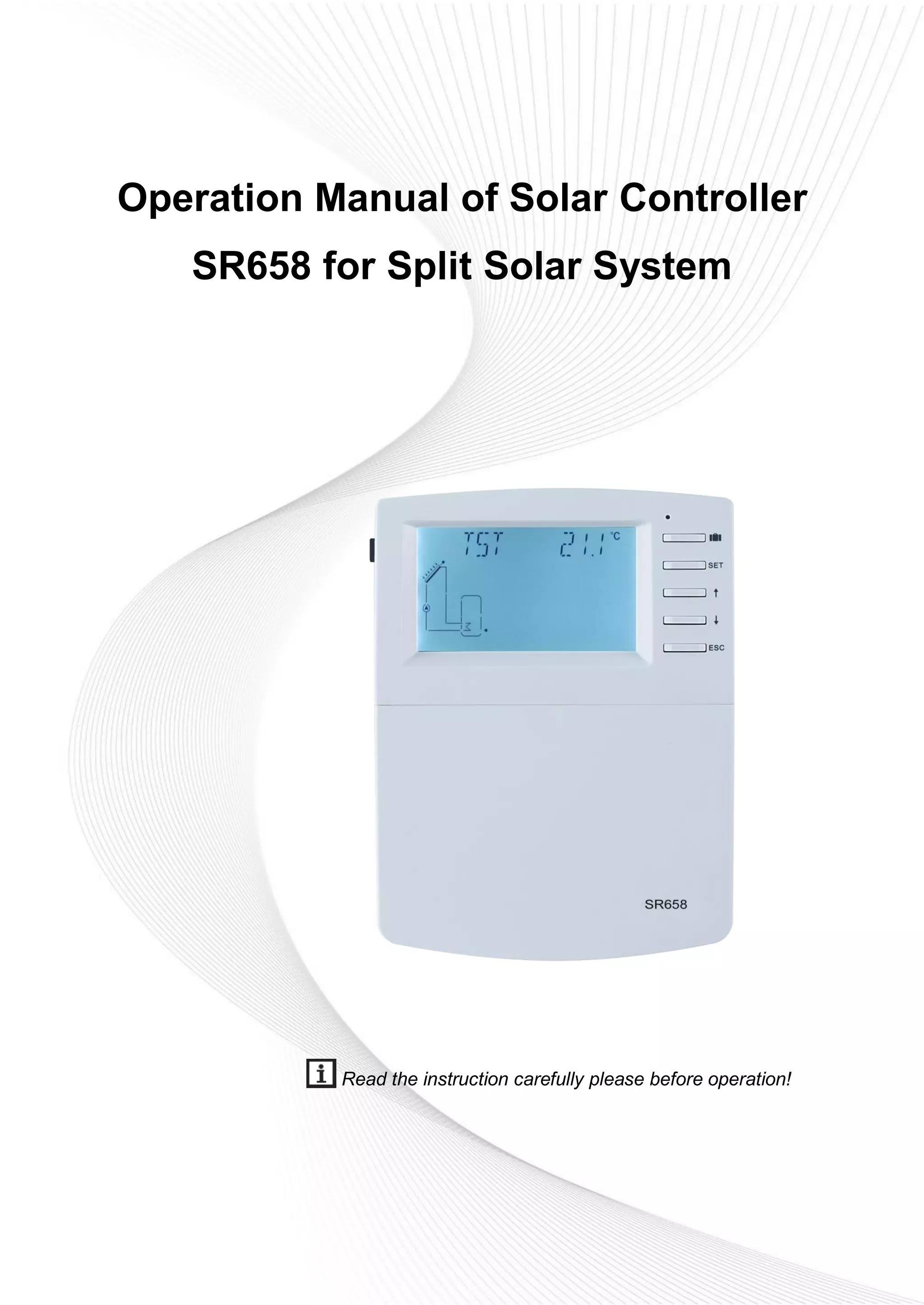

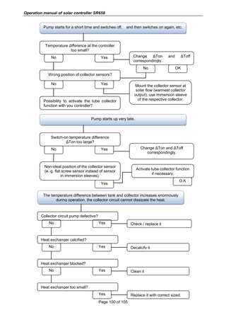
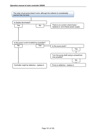
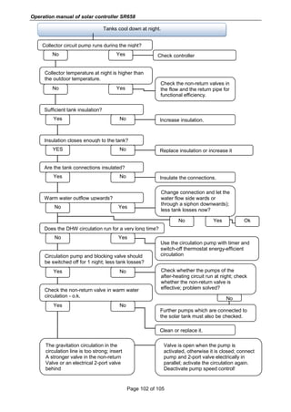
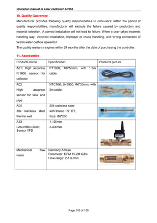
The document is an operation manual for the solar controller SR658 designed for split solar systems, detailing safety information, installation guidelines, system introduction, functions, and operational parameters. It outlines the controller's technical specifications, installation procedures, and menu operations necessary for effective use and maintenance. Additionally, it highlights important safety regulations and the need for professional installation to ensure proper operation and avoid liabilities.


