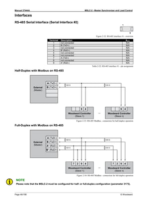
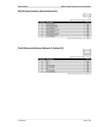
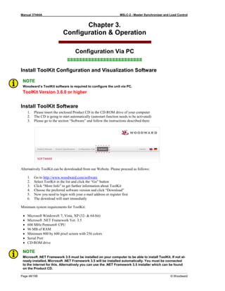
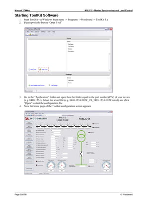
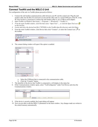
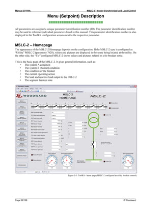
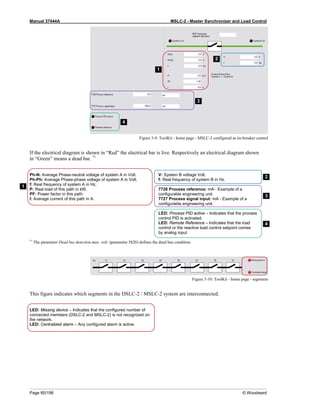
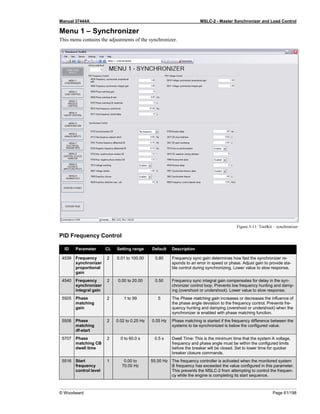
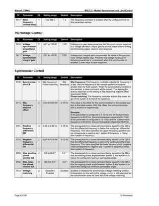
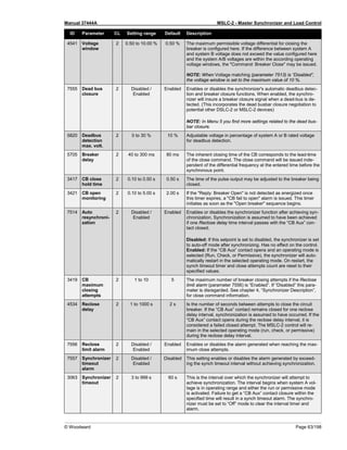
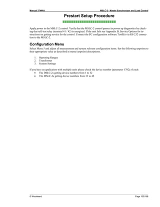
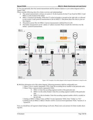
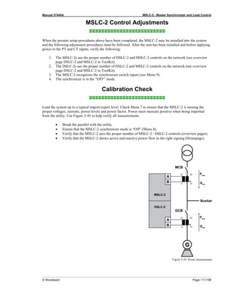
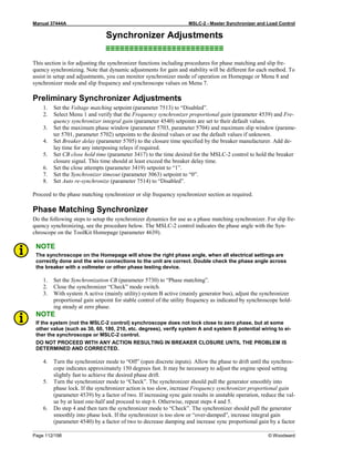
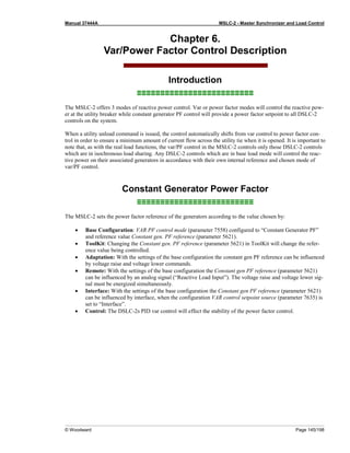
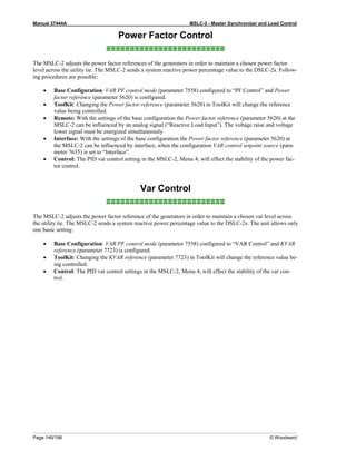
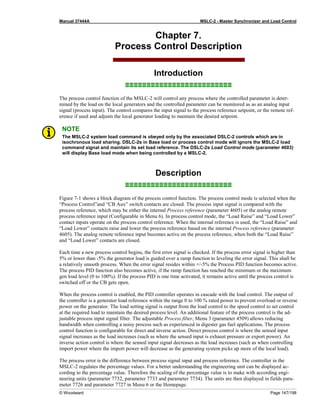
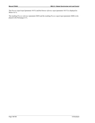
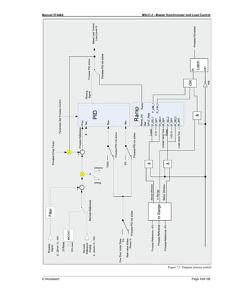
This document provides an overview and instructions for the Master Synchronizer and Load Control (MSLC-2) unit. It discusses the application and functions of the synchronizer, load control, process control, and voltage/VAR/PF control features. The document also covers installation, wiring, configuration, and operation of the MSLC-2 unit via the ToolKit software interface. It provides details on setting up connections to voltage and current measurements, discrete inputs, relay outputs, and communication interfaces. Configuration and monitoring of the MSLC-2 is performed through the ToolKit software menus to control synchronizing, load control, process control, and voltage/VAR/PF functions.
![Manual 37444A MSLC-2 - Master Synchronizer and Load Control
Page 24/198 © Woodward
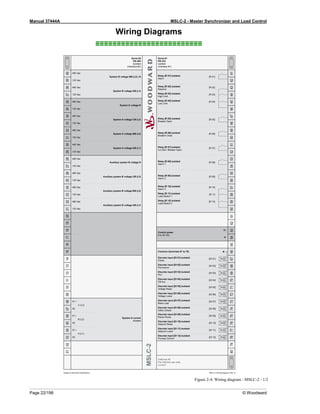
Connections
≡≡≡≡≡≡≡≡≡≡≡≡≡≡≡≡≡≡≡≡≡≡≡≡≡
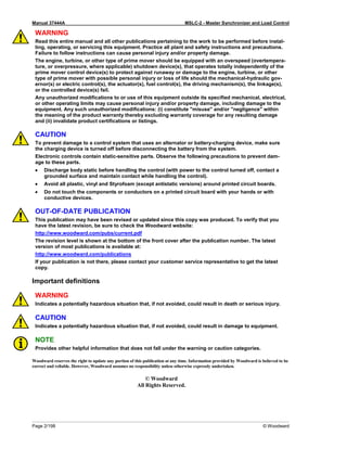
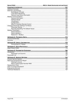
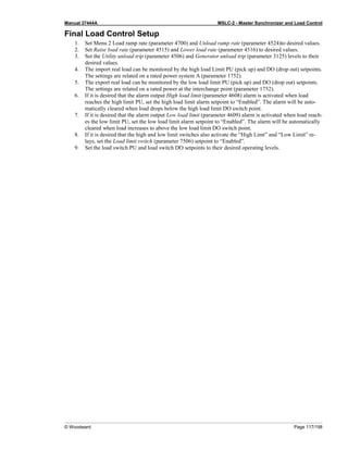
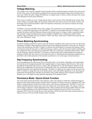
WARNING
All technical data and ratings indicated in this chapter are not definite! Only the values indicated in pa-
ragraph Appendix A. Technical Data on page 174 are valid!
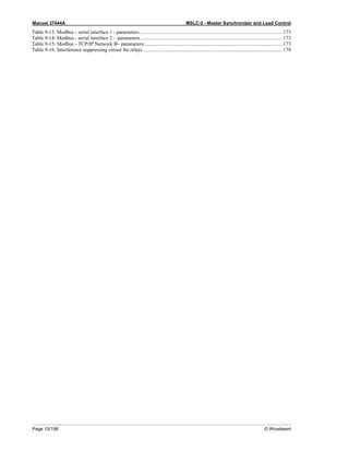
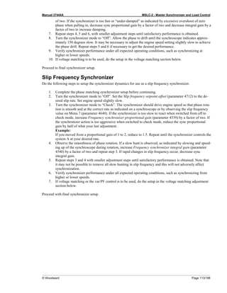
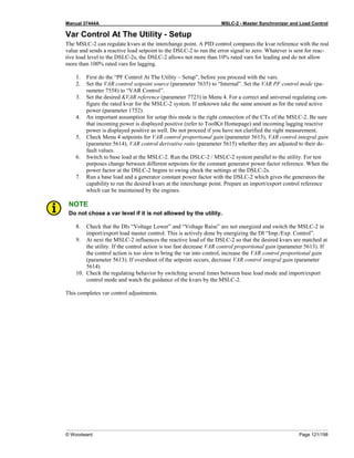
The following chart may be used to convert square millimeters [mm²] to AWG and vice versa:
AWG mm² AWG mm² AWG mm² AWG mm² AWG mm² AWG mm²
30 0.05 21 0.38 14 2.5 4 25 3/0 95 600MCM 300
28 0.08 20 0.5 12 4 2 35 4/0 120 750MCM 400
26 0.14 18 0.75 10 6 1 50 300MCM 150 1000MCM 500
24 0.25 17 1.0 8 10 1/0 55 350MCM 185
22 0.34 16 1.5 6 16 2/0 70 500MCM 240
Table 2-1: Conversion chart - wire size](https://image.slidesharecdn.com/mslc-2product-manualen2017-221130120114-3cc49481/85/MSLC-2_PRODUCT-MANUAL_EN_2017-pdf-24-320.jpg)
![Manual 37444A MSLC-2 - Master Synchronizer and Load Control
© Woodward Page 27/198
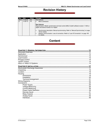
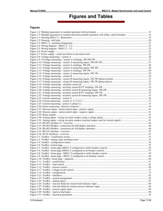
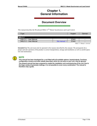
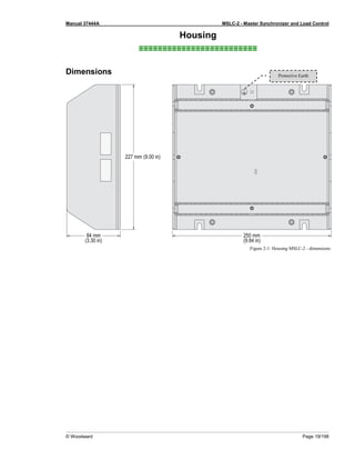
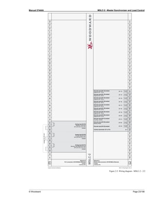
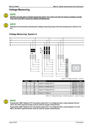
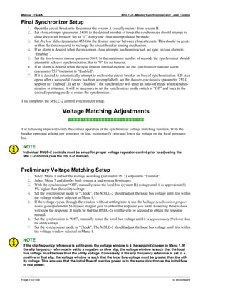
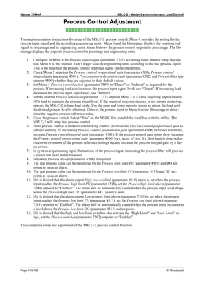
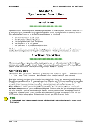
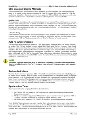
Voltage Measuring: System A
Parameter Setting '3Ph 4W OD' (3-phase, 4-wire, Open delta)
A generator system that is connected to the load through a 3-phase, 4-wire connection but have the device wired
for a 3-phase, 3-wire installation may have the L2 phase grounded on the secondary side. In this application the
device will be configured for 3-phase, 4-wire open delta for correct power measurement.
Figure 2-9: VVoltage measuring – system A windings, 3Ph 4W OD
Figure 2-10: Voltage measuring – system A measuring inputs, 3Ph 4W OD
3Ph 4W OD Wiring terminals Note
Rated voltage (range) [1] 120 V (50 to 130 Veff.) [4] 480 V (131 to 480 Veff.)
1
Measuring range (max.) [1] 0 to 150 Vac [4] 0 to 600 Vac
Figure A C E G B D F H
MSLC-2 terminal 29 31 33 35 30 32 34 36
Phase L1 / AØ L2 / BØ L3 / CØ --- L1 / AØ L2 / BØ L3 / CØ ---
Table 2-4: Voltage measuring - terminal assignment – system A, 3Ph 4W OD
1 For different voltage systems, different wiring terminals have to be used.](https://image.slidesharecdn.com/mslc-2product-manualen2017-221130120114-3cc49481/85/MSLC-2_PRODUCT-MANUAL_EN_2017-pdf-27-320.jpg)
![Manual 37444A MSLC-2 - Master Synchronizer and Load Control
Page 28/198 © Woodward
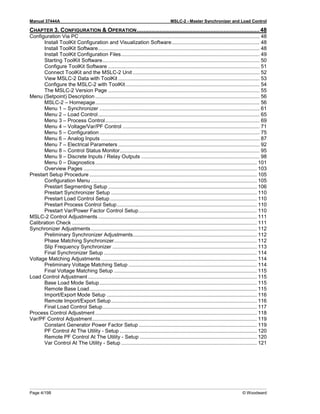
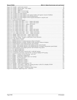
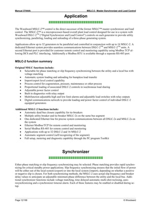
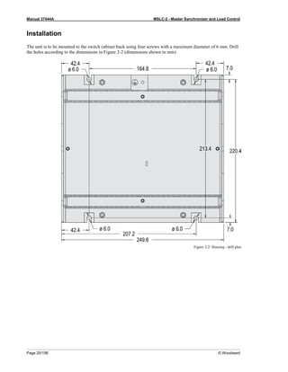
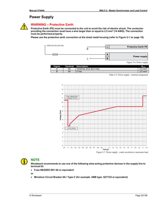
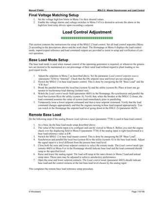
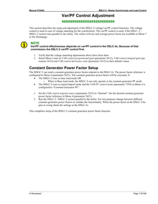
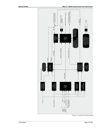
Voltage Measuring: System A, Parameter Setting '3Ph 4W' (3-phase, 4-wire)
Figure 2-11: Voltage measuring – system A windings, 3Ph 4W
Figure 2-12: Voltage measuring – system A measuring inputs, 3Ph 4W
3Ph 4W Wiring terminals Note
Rated voltage (range) [1] 120 V (50 to 130 Veff.) [4] 480 V (131 to 480 Veff.)
2
Measuring range (max.) [1] 0 to 150 Vac [4] 0 to 600 Vac
Figure A C E G B D F H
MSLC-2 terminal 29 31 33 35 30 32 34 36
Phase L1 / AØ L2 / BØ L3 / CØ N L1 / AØ L2 / BØ L3 / CØ N
Table 2-5: Voltage measuring – terminal assignment – system A, 3Ph 4W
2 For different voltage systems, different wiring terminals have to be used. Incorrect measurements are possible if both voltage systems use
the same N terminal.
L1
L2
N
L3
N
A1
A2
A
B
B2
B1
C
C2
C1
L1
L2
N
L3
N
A1
A2
A
B
C6
C5
B6
B5
A5
A6
B2
B1
C
C2
C1
L1
L2
N
L3
N
A1
A2
A
B
B6
B5
A5
A6
C
C6
C5
B2
B1
C2
C1](https://image.slidesharecdn.com/mslc-2product-manualen2017-221130120114-3cc49481/85/MSLC-2_PRODUCT-MANUAL_EN_2017-pdf-28-320.jpg)
![Manual 37444A MSLC-2 - Master Synchronizer and Load Control
© Woodward Page 29/198
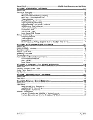
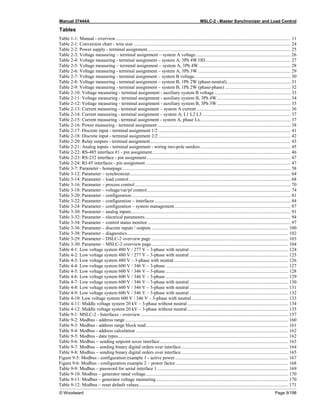
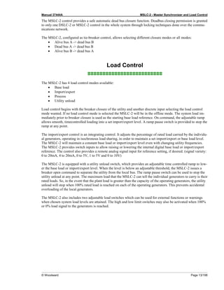
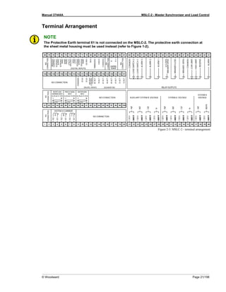
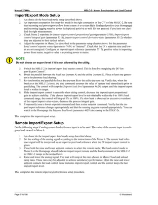
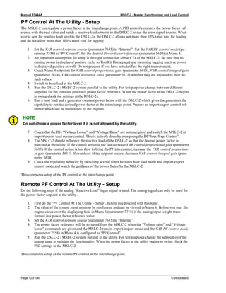
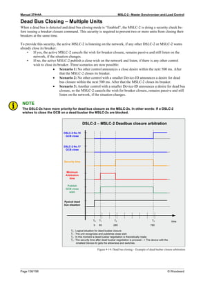
Voltage Measuring: System A, Parameter Setting '3Ph 3W' (3-phase, 3-wire)
Figure 2-13: Voltage measuring – system A windings, 3Ph 3W
Figure 2-14: Voltage measuring – system A measuring inputs, 3Ph 3W
3Ph 3W Wiring terminals Note
Rated voltage (range) [1] 120 V (50 to 130 Veff.) [4] 480 V (131 to 480 Veff.)
3
Measuring range (max.) [1] 0 to 150 Vac [4] 0 to 600 Vac
Figure A C E G B D F H
MSCL-2 terminal 29 31 33 35 30 32 34 36
Phase L1 / AØ L2 / BØ L3 / CØ --- L1 / AØ L2 / BØ L3 / CØ ---
Table 2-6: Voltage measuring - terminal assignment – system A, 3Ph 3W
3 For different voltage systems, different wiring terminals have to be used.
L1
L2
L3
B2
C2
C1
A1
A2
B1
A
B
C
L1
L2
L3
B1
B2
C6
C5
A1
A2
B5
B6
A
B
C
C2
C1
A5
A6](https://image.slidesharecdn.com/mslc-2product-manualen2017-221130120114-3cc49481/85/MSLC-2_PRODUCT-MANUAL_EN_2017-pdf-29-320.jpg)
![Manual 37444A MSLC-2 - Master Synchronizer and Load Control
© Woodward Page 31/198
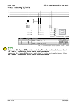
Voltage Measuring: System B, Parameter Setting '1Ph 2W' (1-phase, 2-wire)
NOTE
The 1-phase, 2-wire measurement may be performed phase-neutral or phase-phase. Please note to
configure and wire the MSLC-2 consistently. Refer to the chapter Configuration & Operation.
'1Ph 2W' Phase-Neutral Measuring
Figure 2-16: Voltage measuring – system B measuring inputs, 1Ph 2W (phase-neutral)
1Ph 2W Wiring terminals Note
Rated voltage (range) [1] 120 V (50 to 130 Veff.) [4] 480 V (131 to 480 Veff.)
4
Measuring range (max.) [1] 0 to 150 Vac [4] 0 to 600 Vac
Figure A C --- --- B D --- ---
MSLC-2 terminal 37 39 --- --- 38 40 --- ---
Phase L1 / AØ N --- --- L1 / AØ N --- ---
Table 2-8: Voltage measuring - terminal assignment – system B, 1Ph 2W (phase-neutral)
4 For different voltage systems, different wiring terminals have to be used. Incorrect measurements are possible if both voltage systems use
the same N terminal.](https://image.slidesharecdn.com/mslc-2product-manualen2017-221130120114-3cc49481/85/MSLC-2_PRODUCT-MANUAL_EN_2017-pdf-31-320.jpg)
![Manual 37444A MSLC-2 - Master Synchronizer and Load Control
Page 32/198 © Woodward
'1Ph 2W' Phase-Phase Measuring
Figure 2-17: Voltage measuring – system B measuring inputs, 1Ph 2W (phase-phase)
1Ph 2W Wiring terminals Note
Rated voltage (range) [1] 120 V (50 to 130 Veff.) [4] 480 V (131 to 480 Veff.)
5
Measuring range (max.) [1] 0 to 150 Vac [4] 0 to 600 Vac
Figure A C --- --- B D --- ---
MSLC-2 terminal 37 39 --- --- 38 40 --- ---
Phase L1 / AØ L2 / BØ --- --- L1 / AØ L2 / BØ --- ---
Table 2-9: Voltage measuring - terminal assignment – system B, 1Ph 2W (phase-phase)
5 For different voltage systems, different wiring terminals have to be used. Incorrect measurements are possible if both voltage systems use
the same N terminal.](https://image.slidesharecdn.com/mslc-2product-manualen2017-221130120114-3cc49481/85/MSLC-2_PRODUCT-MANUAL_EN_2017-pdf-32-320.jpg)
![Manual 37444A MSLC-2 - Master Synchronizer and Load Control
Page 34/198 © Woodward
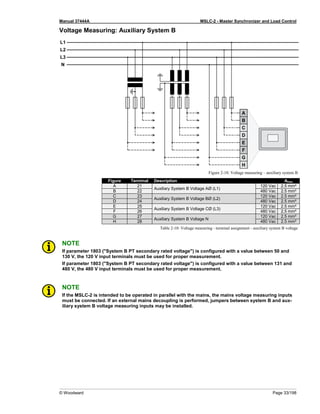
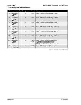
Voltage Measuring: Auxiliary System B, Parameter Setting '3Ph 4W' (3-phase, 4-wire)
Figure 2-19: Voltage measuring - auxiliary system B PT windings, 3Ph 4W
Figure 2-20: Voltage measuring - auxiliary system B measuring inputs, 3Ph 4W
3Ph 4W Wiring terminals Note
Rated voltage (range) [1] 120 V (50 to 130 Veff.) [4] 480 V (131 to 480 Veff.)
6
Measuring range (max.) [1] 0 to 150 Vac [4] 0 to 600 Vac
Figure A C E G B D F H
MSLC-2 terminal 21 23 25 27 22 24 26 28
Phase L1 / AØ L2 / BØ L3 / CØ N L1 / AØ L2 / BØ L3 / CØ N
Table 2-11: Voltage measuring - terminal assignment - auxiliary system B, 3Ph 4W
6 For different voltage systems, different wiring terminals have to be used. Incorrect measurements are possible if both voltage systems use
the same N terminal.
L1
L2
N
L3
N
A1
A2
A
B
B2
B1
C
C2
C1
L1
L2
N
L3
N
A1
A2
A
B
C6
C5
B6
B5
A5
A6
B2
B1
C
C2
C1
L1
L2
N
L3
N
A1
A2
A
B
B6
B5
A5
A6
C
C6
C5
B2
B1
C2
C1](https://image.slidesharecdn.com/mslc-2product-manualen2017-221130120114-3cc49481/85/MSLC-2_PRODUCT-MANUAL_EN_2017-pdf-34-320.jpg)
![Manual 37444A MSLC-2 - Master Synchronizer and Load Control
© Woodward Page 35/198
Voltage Measuring: Auxiliary System B, Parameter Setting '3Ph 3W' (3-phase, 3-wire)
Figure 2-21: Voltage measuring - auxiliary system B PT windings, 3Ph 3W
Figure 2-22: Voltage measuring - auxiliary system B measuring inputs, 3Ph 3W
3Ph 3W Wiring terminals Note
Rated voltage (range) [1] 120 V (50 to 130 Veff.) [4] 480 V (131 to 480 Veff.)
7
Measuring range (max.) [1] 0 to 150 Vac [4] 0 to 600 Vac
Figure A C E G B D F H
MSLC-2 terminal 21 23 25 27 22 24 26 28
Phase L1 / AØ L2 / BØ L3 / CØ --- L1 / AØ L2 / BØ L3 / CØ ---
Table 2-12: Voltage measuring - terminal assignment - auxiliary system B, 3Ph 3W
7 For different voltage systems, different wiring terminals have to be used.
L1
L2
L3
B2
C2
C1
A1
A2
B1
A
B
C
L1
L2
L3
B1
B2
C6
C5
A1
A2
B5
B6
A
B
C
C2
C1
A5
A6](https://image.slidesharecdn.com/mslc-2product-manualen2017-221130120114-3cc49481/85/MSLC-2_PRODUCT-MANUAL_EN_2017-pdf-35-320.jpg)
![Manual 37444A MSLC-2 - Master Synchronizer and Load Control
© Woodward Page 41/198
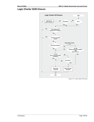
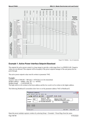
Discrete Inputs
Discrete Inputs: Signal Polarity
The discrete inputs are electrically isolated which permits the polarity of the connections to be either positive or
negative.
NOTE
All discrete inputs must use the same polarity, either positive or negative signals, due to the common
ground.
Discrete Inputs: Positive Polarity Signal
Figure 2-27: Discrete inputs - alarm/control input - positive signal
Discrete Inputs: Negative Polarity Signal
Figure 2-28: Discrete inputs - alarm/control input - negative signal
Terminal Description Amax
Term. Com.
A B
66
GND
com-
mon
ground
67 Discrete input [DI 01] {all} Check 2.5 mm²
68 Discrete input [DI 02] {all} Permissive 2.5 mm²
69 Discrete input [DI 03] {all} Run 2.5 mm²
70 Discrete input [DI 04] {all} CB Aux 2.5 mm²
71 Discrete input [DI 05] {all} Voltage Raise 2.5 mm²
72 Discrete input [DI 06] {all} Voltage Lower 2.5 mm²
73 Discrete input [DI 07] {all} Base Load 2.5 mm²
74 Discrete input [DI 08] {all} Utility Unload 2.5 mm²
75 Discrete input [DI 09] {all} Ramp Pause 2.5 mm²
76 Discrete input [DI 10] {all} Setpoint Raise 2.5 mm²
77 Discrete input [DI 11] {all} Setpoint Lower 2.5 mm²
78 Discrete input [DI 12] {all} Process Control 2.5 mm²
Table 2-17: Discrete input - terminal assignment 1/2](https://image.slidesharecdn.com/mslc-2product-manualen2017-221130120114-3cc49481/85/MSLC-2_PRODUCT-MANUAL_EN_2017-pdf-41-320.jpg)
![Manual 37444A MSLC-2 - Master Synchronizer and Load Control
Page 42/198 © Woodward
Terminal Description Amax
Term. Com.
A B
152
GND
com-
mon
ground
141 Discrete input [DI 13] {all} Segment No. 12 Act. 2.5 mm²
142 Discrete input [DI 14] {all} Segment No. 23 Act. 2.5 mm²
143 Discrete input [DI 15] {all} Segment No. 34 Act. 2.5 mm²
144 Discrete input [DI 16] {all} Segment No. 45 Act. 2.5 mm²
145 Discrete input [DI 17] {all} Segment No. 56 Act. 2.5 mm²
146 Discrete input [DI 18] {all} Segment No. 67 Act. 2.5 mm²
147 Discrete input [DI 19] {all} Segment No. 78 Act. 2.5 mm²
148 Discrete input [DI 20] {all} Segment No. 81 Act. 2.5 mm²
149 Discrete input [DI 21] {all} Imp./Exp. Control 2.5 mm²
150 Discrete input [DI 22] {all} Modbus Reset 2.5 mm²
151 Discrete input [DI 23] {all} Reserved 2.5 mm²
Table 2-18: Discrete input - terminal assignment 2/2
DI
CB AUX
DI
Utility
Unload
DI
Base Load
DI
Imp/Exp
Control
DI
Process
Control
DI
Ramp Pause
DI
Setpoint
Raise
DI
Setpoint
Lower
Off Line 0 x x x x x x x
Base Load 1 0 1 0 0 0 0 0
Base Load Raise 1 0 1 0 0 0 1 0
Base Load Lower 1 0 1 0 0 0 0 1
Base Load 1
Remote
1 0 1 0 0 0 1 1
Utility Unload 2
1 1 x x x 0 x x
Local Unload 3
1 0 1 0 0 0 0 1
Ramp Pause 4
1 x x x x 1 x x
Import/
Export mode
1 0 x 1 0 0 0 0
I/E Raise 1 0 x 1 0 0 1 0
I/E Lower 1 0 x 1 0 0 0 1
I/E Remote 1
1 0 x 1 0 0 1 1
Process Control 1 0 x x 1 0 0 0
Process Raise 1 0 x x 1 0 1 0
Process Lower 1 0 x x 1 0 0 1
Process Remote 1
1 0 x x 1 0 1 1
Table 2-19: Load control modes MSLC-2
1
Remote reference is activated by closing both setpoint raise and setpoint lower switches at the same time.
2
The MSLC-2 can only load the associated generators to 100%. If this is not enough capacity to unload the utility, the unload ramps stops at
100% rated load on the associated generators. The generator high limit alarm, if enabled, will activate at this time.
3
The local plant unload is accomplished by switching to base load mode and supplying a continuous setpoint lower command.
4
The ramp pause command will pause all ramps in any mode.](https://image.slidesharecdn.com/mslc-2product-manualen2017-221130120114-3cc49481/85/MSLC-2_PRODUCT-MANUAL_EN_2017-pdf-42-320.jpg)
![Manual 37444A MSLC-2 - Master Synchronizer and Load Control
© Woodward Page 43/198
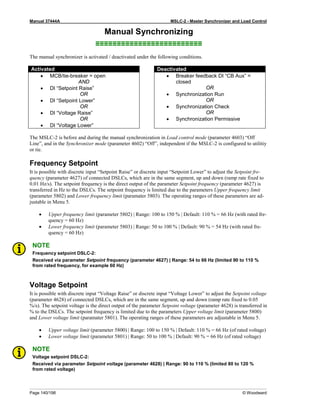
Relay Outputs
Figure 2-29: Relay outputs
Terminal Description Amax
Term. Com.
A B Form A, N.O. make contact Type
42 41 Relay output [R 01] {all} Alarm (Self Test OK) N.O. 2.5 mm²
43
46
Relay output [R 02] {all} Reserve N.O. 2.5 mm²
44 Relay output [R 03] {all} High Limit N.O. 2.5 mm²
45 Relay output [R 04] {all} Low Limit N.O. 2.5 mm²
48 47 Relay output [R 05] {all} Breaker Open N.O. 2.5 mm²
50 49 Relay output [R 06] {all} Breaker Close N.O. 2.5 mm²
52 51 Relay output [R 07] {all} Lcl./Gen. Breaker Open N.O. 2.5 mm²
54 53 Relay output [R 08] {all} Alarm 1 N.O. 2.5 mm²
56 55 Relay output [R 09] {all} Alarm 2 N.O. 2.5 mm²
57
60
Relay output [R 10] {all} Alarm 3 N.O. 2.5 mm²
58 Relay output [R 11] {all} Load Switch 1 N.O. 2.5 mm²
59 Relay output [R 12] {all} Load Switch 2 N.O. 2.5 mm²
N.O.-normally open (make) contact
Table 2-20: Relay outputs - terminal assignment](https://image.slidesharecdn.com/mslc-2product-manualen2017-221130120114-3cc49481/85/MSLC-2_PRODUCT-MANUAL_EN_2017-pdf-43-320.jpg)
![Manual 37444A MSLC-2 - Master Synchronizer and Load Control
© Woodward Page 45/198
Analog Inputs
The following senders may be used for the analog inputs:
• 0 to 20mA
• 4 to 20mA
• 0 to 10V
• 0 to 5V
• 1 to 5V
Wiring Examples
Figure 2-30: Analog inputs - wiring two-pole senders using a voltage signal
Figure 2-31: Analog inputs - wiring two-pole senders (external jumper used for current signal)
Figure Terminal Description Amax
A 83
Analog input [AI 01]
Remote Load Reference Input
2.5 mm²
B 84 2.5 mm²
C 85 + 2.5 mm²
A 86
Analog input [AI 02]
Process Signal Input
2.5 mm²
B 87 2.5 mm²
C 88 + 2.5 mm²
A 89
Analog input [AI 03]
Reactive Load Input
2.5 mm²
B 90 2.5 mm²
C 91 + 2.5 mm²
Table 2-21: Analog inputs - terminal assignment - wiring two-pole senders](https://image.slidesharecdn.com/mslc-2product-manualen2017-221130120114-3cc49481/85/MSLC-2_PRODUCT-MANUAL_EN_2017-pdf-45-320.jpg)
![Manual 37444A MSLC-2 - Master Synchronizer and Load Control
© Woodward Page 49/198
Install ToolKit Configuration Files
1. Please insert the enclosed Product CD in the CD-ROM drive of your computer
2. The CD is going to start automatically (autostart function needs to be activated)
3. Please go to the section “Configuration Files” and follow the instructions described there
Alternatively ToolKit configuration files can be downloaded from our Website. Please proceed as follows:
1. Go to http://www.woodward.com/software/configfiles/
2. Please insert the part number (P/N) and revision of your device into the corresponding fields
3. Select ToolKit in the application type list
4. Click “Search”
NOTE
ToolKit is using the following files:
*.WTOOL
File name composition:[P/N1]*
1
-[Revision]_[Language ID]_[P/N2]*
2
-[Revision]_[# of visualized
gens].WTOOL
Example file name: 8440-1234-NEW_US_5418-1234-NEW.WTOOL
Content of the file: Display screens and pages for online configuration, which are associated with
the respective *.SID file
*.SID
File name composition:[P/N2]*
2
-[Revision].SID
Example file name: 5418-1234-NEW.SID
Content of the file: All display and configuration parameters available in ToolKit
*.WSET
File name composition:[user defined].WSET
Example file name: easYgen_settings.WSET
Content of the file: Default settings of the ToolKit configuration parameters provided by the SID
file or user-defined settings read out of the unit.
*
1
P/N1 = Part number of the unit
*
2
P/N2 = Part number of the software in the unit](https://image.slidesharecdn.com/mslc-2product-manualen2017-221130120114-3cc49481/85/MSLC-2_PRODUCT-MANUAL_EN_2017-pdf-49-320.jpg)


![Manual 37444A MSLC-2 - Master Synchronizer and Load Control
Page 84/198 © Woodward
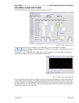
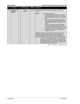
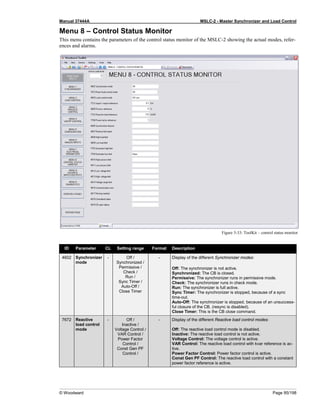
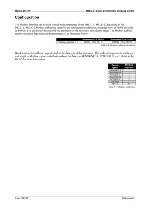
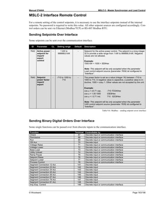
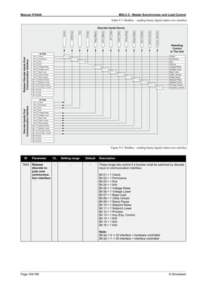
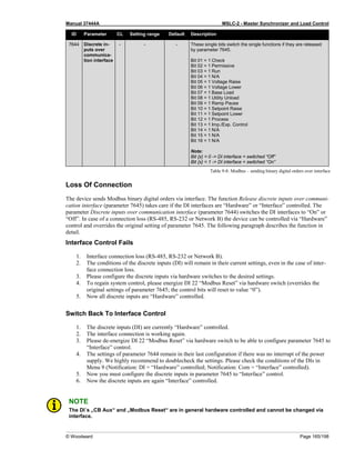
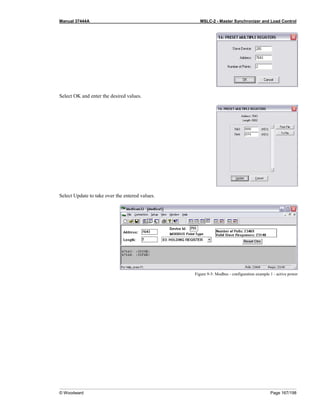
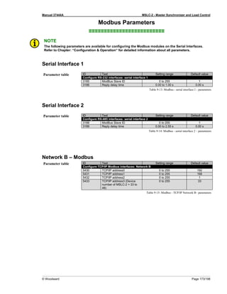
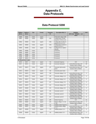
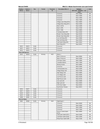
Modbus Interface Definitions
The unit offers a Modbus address table with for visualizing systems. The table contains 16bit integer (short) and
32bit integer (long) variables. The contents of some measurement long variables are also available as short va-
riables. To cover all measurement ranges in a satisfying resolution, the engineering unit “Watt”, “Volt” and
“Ampere” can be adjusted according to the application.
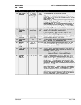
ID Parameter CL Setting range Default Description
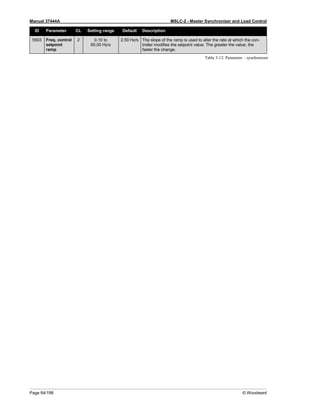
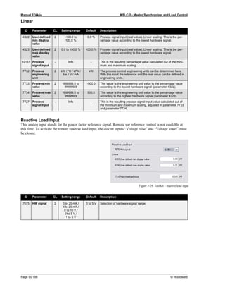
3181 Power [W]
exponent
10^x
2 2 to 5 3 This setting adjusts the format of the 16 bit power values in the
data telegram.
Example power measurement:
The measurement range is 0 to 250 kW.
Momentarily measurement value = 198.5 kW (198.500 W)
Setting Meaning Calcula-
tion
Transfer
value
(16Bit,
max.
32767)
Possible
Display
Format
2 102 198500 𝑊
102 𝑊
1985 198.5 kW
3 103 198500 𝑊
103 𝑊
198 198 kW
4 104 198500 𝑊
104 𝑊
19 N/A
5 105 198500 𝑊
105 𝑊
1 N/A
3182 Volts [V]
exponent
10^x
2 -1 to 2 0 This setting adjusts the format of the 16 bit voltage values in the
data telegram.
Example voltage measurement:
The measurement range is 0 to 480 V.
Momentarily measurement value = 477.8 V
Setting Meaning Calcula-
tion
Transfer
value
(16Bit,
max.
32767)
Possible
Display
Format
-1 10-1 477.8 𝑉
10−1 𝑉
4778 477.8 V
0 100 477.8 𝑉
100 𝑉
477 477 V
1 101 477.8 𝑉
101 𝑉
47 N/A
2 102 477.8 𝑉
102 𝑉
4 N/A
3183 Current [A]
exponent
10^x
2 -1 to 0 0 This setting adjusts the format of the 16 bit current values in the
data telegram.
Example current measurement:
The measurement range is 0 to 500 A
Momentarily measurement value = 345.4 A
Setting Meaning Calcula-
tion
Transfer
value
(16Bit,
max.
32767)
Possible
Display
Format
-1 10-1 345.4 𝐴
10−1 𝑉
3454 345.4 A
0 100 345.4 𝑉
100 𝑉
345 345 A
Table 3-22: Parameter – configuration – interfaces](https://image.slidesharecdn.com/mslc-2product-manualen2017-221130120114-3cc49481/85/MSLC-2_PRODUCT-MANUAL_EN_2017-pdf-84-320.jpg)
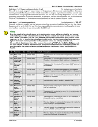
![Manual 37444A MSLC-2 - Master Synchronizer and Load Control
Page 98/198 © Woodward
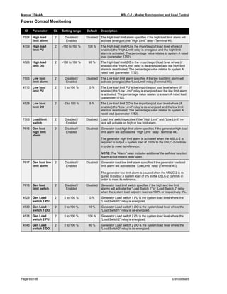
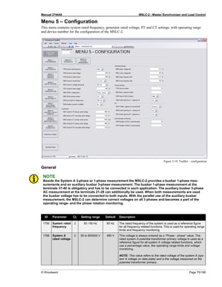
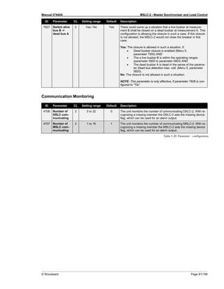
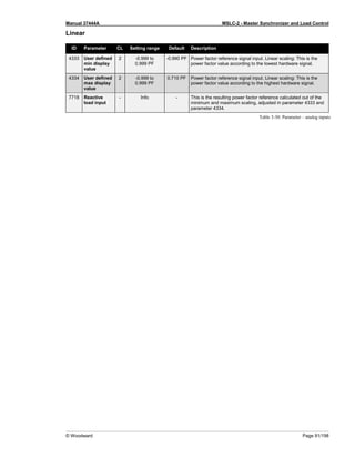
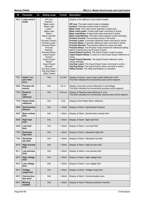
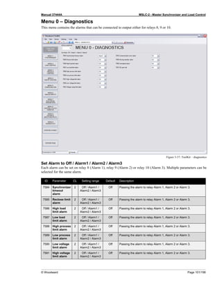
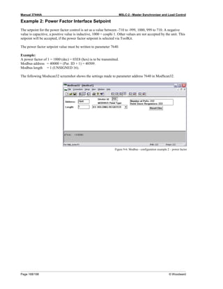
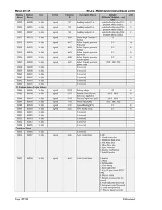
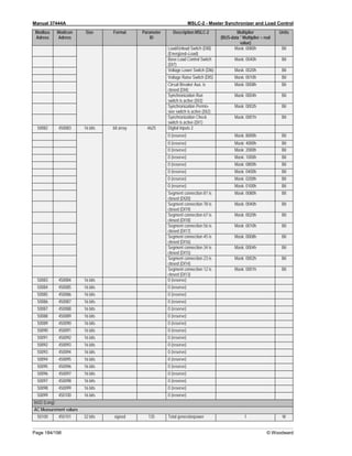
Menu 9 – Discrete Inputs / Relay Outputs
This menu contains the parameters for the discrete inputs, the discrete input source (hardware or communication
interface) and the discrete outputs (relays) of the MSLC-2.
Figure 3-35: ToolKit – discrete inputs / relay outputs
Discrete Inputs
ID Parameter CL Setting range Default Description
7671 Check
switch
- Open / Closed Open Display of discrete input state for [DI 01]: Check.
7671 Permissive
switch
- Open / Closed Open Display of discrete input state for [DI 02]: Permissive.
7671 Run switch - Open / Closed Open Display of discrete input state for [DI 03]: Run.
7671 CB Aux
contact
- Open / Closed Open Display of discrete input state for [DI 04]: CB Aux.
7671 Voltage raise
switch
- Open / Closed Open Display of discrete input state for [DI 05]: Voltage raise
7671 Voltage
lower switch
- Open / Closed Open Display of discrete input state for [DI 06]: Voltage lower
7671 Base load
switch
- Open / Closed Open Display of discrete input state for [DI 07]: Base load.
7671 Utility unload - Open / Closed Open Display of discrete input state for [DI 08]: Utility unload.
7671 Ramp pause
switch
- Open / Closed Open Display of discrete input state for [DI 09]: Ramp pause.
7671 Setpoint
raise switch
- Open / Closed Open Display of discrete input state for [DI 10]: Setpoint raise](https://image.slidesharecdn.com/mslc-2product-manualen2017-221130120114-3cc49481/85/MSLC-2_PRODUCT-MANUAL_EN_2017-pdf-98-320.jpg)
![Manual 37444A MSLC-2 - Master Synchronizer and Load Control
© Woodward Page 99/198
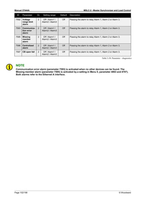
ID Parameter CL Setting range Default Description
7671 Setpoint
lower switch
- Open / Closed Open Display of discrete input state for [DI 11]: Setpoint lower
7671 Process
control
switch
- Open / Closed Open Display of discrete input state for [DI 12]: Process control
7604 Segment
no .12 active
- Open / Closed Open Display of discrete input state for [DI 13]: Segment no 12 active.
7605 Segment
no .23 active
- Open / Closed Open Display of discrete input state for [DI 14]: Segment no 23 active.
7606 Segment
no .34 active
- Open / Closed Open Display of discrete input state for [DI 15]: Segment no 34 active.
7607 Segment
no .45 active
- Open / Closed Open Display of discrete input state for [DI 16]: Segment no 45 active.
7608 Segment
no .56 active
- Open / Closed Open Display of discrete input state for [DI 17]: Segment no 56 active.
7609 Segment
no .67 active
- Open / Closed Open Display of discrete input state for [DI 18]: Segment no 67 active.
7610 Segment
no .78 active
- Open / Closed Open Display of discrete input state for [DI 19]: Segment no 78 active.
7611 Segment
no .81 active
- Open / Closed Open Display of discrete input state for [DI 20]: Segment no 81 active.
7671 Import
/Export
switch
- Open / Closed Open Display of discrete input state for [DI 21]: Import/Export control.
Discrete Input Source
ID Parameter CL Setting range Default Description
4157 Source-
Check
switch
- DI / COM DI Indicates the source of “Check” switch either DI or communication
interface.
4157 Source-
Permissive
switch
- DI / COM DI Indicates the source of “Permissive” switch either DI or communi-
cation interface.
4157 Source-Run
switch
- DI / COM DI Indicates the source of “Run” switch either DI or communication
interface.
4157 Source-CB
Aux contact
- DI / COM DI Indicates the source of “CB Aux” switch either DI or communica-
tion interface.
4157 Source-
Voltage raise
switch
- DI / COM DI Indicates the source of “Voltage Raise” switch either DI or com-
munication interface.
4157 Source-
Voltage low-
er switch
- DI / COM DI Indicates the source of “Voltage Lower” switch either DI or com-
munication interface.
4157 Source-Base
load switch
- DI / COM DI Indicates the source of “Base Load” switch either DI or communi-
cation interface.
4157 Source-
Utility unload
switch
- DI / COM DI Indicates the source of “Utility Unload” switch either DI or commu-
nication interface.
4157 Source
Ramp pause
switch
- DI / COM DI Indicates the source of “Ramp Pause” switch either DI or commu-
nication interface.
4157 Source-
Setpoint
raise switch
- DI / COM DI Indicates the source of “Setpoint Raise” switch either DI or com-
munication interface.](https://image.slidesharecdn.com/mslc-2product-manualen2017-221130120114-3cc49481/85/MSLC-2_PRODUCT-MANUAL_EN_2017-pdf-99-320.jpg)
![Manual 37444A MSLC-2 - Master Synchronizer and Load Control
Page 100/198 © Woodward
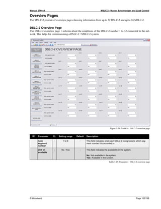
ID Parameter CL Setting range Default Description
4157 Source-
Setpoint
lower switch
- DI / COM DI Indicates the source of “Setpoint Lower” switch either DI or com-
munication interface.
4157 Source-
Process con-
trol switch
- DI / COM DI Indicates the source of “Process Control” switch either DI or
communication interface.
4157 Source-
Im-
port/Export
switch
- DI / COM DI Indicates the source of “Imp./Exp. Control” switch either DI or
communication interface.
Relay Outputs
ID Parameter CL Setting range Default Description
7572 Alarm - Open / Closed Closed Display of relay output state for [R 01]: Alarm.
7574 High limit - Open / Closed Open Display of relay output state for [R 03]: High limit.
7575 Low limit - Open / Closed Open Display of relay output state for [R 04]: Low limit.
7576 Breaker
open
- Open / Closed Open Display of relay output state for [R 05]: Breaker open.
7577 Breaker
close
- Open / Closed Open Display of relay output state for [R 06]: Breaker close.
7578 LCL/Gen
breaker open
- Open / Closed Open Display of relay output state for [R 07]: LCL/Gen breaker open.
7579 Alarm 1 - Open / Closed Open Display of relay output state for [R 08]: Alarm 1.
7580 Alarm 2 - Open / Closed Open Display of relay output state for [R 09]: Alarm 2.
7581 Alarm 3 - Open / Closed Open Display of relay output state for [R 10]: Alarm 3.
7582 Load
switch 1
- Open / Closed Open Display of relay output state for [R 11]: Load switch 1.
7583 Load
switch 2
- Open / Closed Open Display of relay output state for [R 12]: Load switch 2.
Table 3-36: Parameter – discrete inputs / outputs](https://image.slidesharecdn.com/mslc-2product-manualen2017-221130120114-3cc49481/85/MSLC-2_PRODUCT-MANUAL_EN_2017-pdf-100-320.jpg)
![Manual 37444A MSLC-2 - Master Synchronizer and Load Control
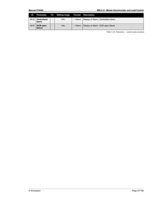
Page 124/198 © Woodward
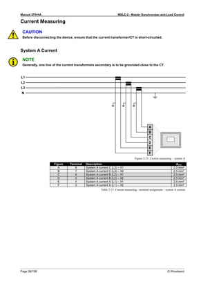
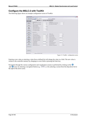
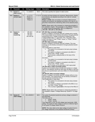
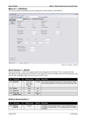
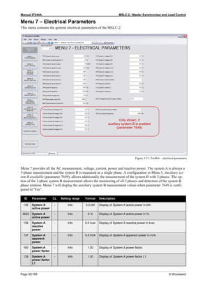
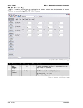
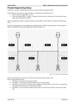
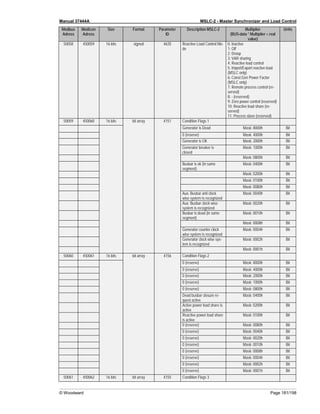
Measurement Connections (Examples)
Low Voltage System 480 V / 277 V - 3-Phase with Neutral
• Phase rotation clockwise
• System A measurement: 3-Phase with neutral
• System B measurement : L1-L2 (“Phase – phase”)
Figure 4-2: Low voltage system 480 V / 277 V – 3-phase with neutral
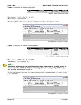
Configuration Measurement Voltage Monitoring
Menu 5
• System A rated voltage (parameter 1766): “480 V”
• System A current input (parameter 1850): “L1 L2 L3”
• System A voltage measuring (parameter 1851): “3Ph 4W”
• System B rated voltage (parameter 1781): “480 V”
• 1Ph2W voltage input (parameter 1858): “Phase – phase”
• 1Ph2W phase rotation (parameter 1859): “CW”
• Auxiliary Sytem B available (parameter 7629): “No”
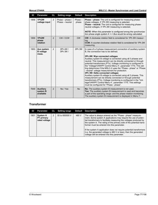
Transformer
• System A PT primary rated voltage (parameter 1801): “480 V”
• System A PT secondary rated volt. (parameter 1800): “480 V”
• System B PT primary rated voltage (parameter 1804): “480 V”
• System B PT secondary rated volt. (parameter 1803): “480 V”
• Systen A [V] L1
• Systen A [V] L2
• Systen A [V] L3
• Systen A [V] L1-L2
• Systen A [V] L2-L3
• Systen A [V] L3-L1
• Systen A [A] L1
• Systen A [A] L2
• Systen A [A] L3
• Systen A [kW]
• Systen A [KVA]
• Systen A [kvar]
• Systen A [PF] L1
• Systen A [PF] L2
• Systen A [PF] L3
• Systen A [Hz]
• Systen A Phase rota-
tion
• System B [V] L1-L2
• System B [Hz]
• Phase-Angle
• System B-A
• System A [V] L1
• System A [V] L2
• System A [V] L3
OR
• System A [V] L1-L2
• System A [V] L2-L3
• System A [V] L3-L1
Table 4-1: Low voltage system 480 V / 277 V – 3-phase with neutral](https://image.slidesharecdn.com/mslc-2product-manualen2017-221130120114-3cc49481/85/MSLC-2_PRODUCT-MANUAL_EN_2017-pdf-124-320.jpg)
![Manual 37444A MSLC-2 - Master Synchronizer and Load Control
© Woodward Page 125/198
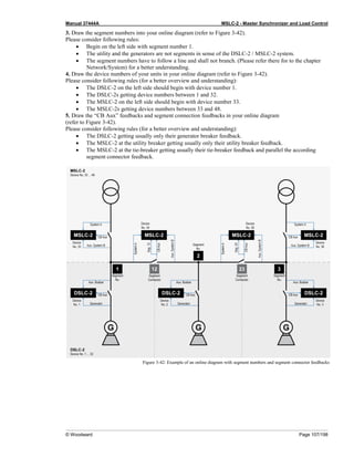
Low Voltage System 480 V / 277 V - 3-Phase with Neutral
• Phase rotation clockwise
• System A measurement: 3-Phase with neutral
• System B measurement : L1-N (“Phase – neutral”)
Figure 4-3: Low voltage system 480 V / 277 V – 3-phase with neutral
Configuration Measurement Voltage Monitoring
Menu 5
• System A rated voltage (parameter 1766): “480 V”
• System A current input (parameter 1850): “L1 L2 L3”
• System A voltage measuring (parameter 1851): “3Ph 4W”
• System B rated voltage (parameter 1781): “277 V”
• 1Ph2W voltage input (parameter 1858): “Phase – neutral”
• 1Ph2W phase rotation (parameter 1859): “CW”
• Auxiliary Sytem B available (parameter 7629): “No”
Transformer
• System A PT primary rated voltage (parameter 1801): “480 V”
• System A PT secondary rated volt. (parameter 1800): “480 V”
• System B PT primary rated voltage (parameter 1804): “480 V”
• System B PT secondary rated volt. (parameter 1803): “480 V”
• Systen A [V] L1
• Systen A [V] L2
• Systen A [V] L3
• Systen A [V] L1-L2
• Systen A [V] L2-L3
• Systen A [V] L3-L1
• Systen A [A] L1
• Systen A [A] L2
• Systen A [A] L3
• Systen A [kW]
• Systen A [KVA]
• Systen A [kvar]
• Systen A [PF] L1
• Systen A [PF] L2
• Systen A [PF] L3
• Systen A [Hz]
• Systen A Phase rota-
tion
• System B [V] L1
• System B [Hz]
• Phase-Angle
• System B-A
• System A [V] L1
• System A [V] L2
• System A [V] L3
OR
• System A [V] L1-L2
• System A [V] L2-L3
• System A [V] L3-L1
Table 4-2: Low voltage system 480 V / 277 V – 3-phase with neutral](https://image.slidesharecdn.com/mslc-2product-manualen2017-221130120114-3cc49481/85/MSLC-2_PRODUCT-MANUAL_EN_2017-pdf-125-320.jpg)
![Manual 37444A MSLC-2 - Master Synchronizer and Load Control
Page 126/198 © Woodward
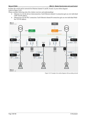
Low Voltage System 480 V - 3-Phase with Neutral
• Phase rotation clockwise
• System A measurement: 3-Phase with neutral
• System B measurement : L1-N (“Phase – neutral”)
• Auxiliary system B busbar measurement: 3-Phase with neutral
Figure 4-4: Low voltage system 480 V – 3-phase with neutral
Configuration Measurement Voltage Monitoring
Menu 5
• System A rated voltage (parameter 1766): “480 V”
• System A current input (parameter 1850): “L1 L2 L3”
• System A voltage measuring (parameter 1851): “3Ph 4W”
• System B rated voltage (parameter 1781): “277 V”
• 1Ph2W voltage input (parameter 1858): “Phase – neutral”
• 1Ph2W phase rotation (parameter 1859): “CW”
• Auxiliary Sytem B available (parameter 7629): “Yes”
• Aux System B voltage measuring (parameter 1853): “3Ph 4W”
Transformer
• System A PT primary rated voltage (parameter 1801): “480 V”
• System A PT secondary rated volt. (parameter 1800): “480 V”
• System B PT primary rated voltage (parameter 1804): “480 V”
• System B PT secondary rated volt. (parameter 1803): “480 V”
• Systen A [V] L1
• Systen A [V] L2
• Systen A [V] L3
• Systen A [V] L1-L2
• Systen A [V] L2-L3
• Systen A [V] L3-L1
• Systen A [A] L1
• Systen A [A] L2
• Systen A [A] L3
• Systen A [kW]
• Systen A [KVA]
• Systen A [kvar]
• Systen A [PF] L1
• Systen A [PF] L2
• Systen A [PF] L3
• Systen A [Hz]
• Systen A Phase rotation
• System B [V] L1
• System B [Hz]
• Phase-Angle
• System B-A
• Aux System B [V] L1
• Aux System B [V] L2
• Aux System B [V] L3
• Aux System B [V] L1-L2
• Aux System B [V] L2-L3
• Aux System B [V] L3-L1
• Aux System B phase ro-
tation
• Aux System B [Hz]
• System A [V] L1
• System A [V] L2
• System A [V] L3
OR
• System A [V] L1-L2
• System A [V] L2-L3
• System A [V] L3-L1
Table 4-3: Low voltage system 480 V – 3-phase with neutral](https://image.slidesharecdn.com/mslc-2product-manualen2017-221130120114-3cc49481/85/MSLC-2_PRODUCT-MANUAL_EN_2017-pdf-126-320.jpg)
![Manual 37444A MSLC-2 - Master Synchronizer and Load Control
© Woodward Page 127/198
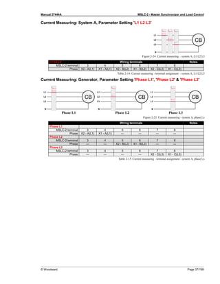
Low Voltage System 600 V / 346 V - 3-Phase
• Phase rotation clockwise
• System A measurement: 3-Phase PT “Open Delta” (Phase L2 (B) is grounded at the MSLC-2 connec-
tion)
• System B measurement: 1-Phase PT L1-L2 (“Phase – phase”)
Figure 4-5: Low voltage system 600 V / 346 V – 3-phase
Configuration Measurement Voltage Monitoring
Menu 5
• System A rated voltage (parameter 1766): “600 V”
• System A current input (parameter 1850): “L1 L2 L3”
• System A voltage measuring (parameter 1851): “3Ph 4W OD”
• System B rated voltage (parameter 1781): “600 V”
• 1Ph2W voltage input (parameter 1858): “Phase – phase”
• 1Ph2W phase rotation (parameter 1859): “CW”
• Auxiliary Sytem B available (parameter 7629): “No”
Transformer
• System A PT primary rated voltage (parameter 1801): “600 V”
• System A PT secondary rated volt. (parameter 1800): “120 V”
• System B PT primary rated voltage (parameter 1804): “600 V”
• System B PT secondary rated volt. (parameter 1803): “120 V”
• Systen A [V] L1-L2
• Systen A [V] L2-L3
• Systen A [V] L3-L1
• Systen A [A] L1
• Systen A [A] L2
• Systen A [A] L3
• Systen A [kW]
• Systen A [KVA]
• Systen A [kvar]
• Systen A [PF] L1
• Systen A [PF] L2
• Systen A [PF] L3
• Systen A [Hz]
• Systen A Phase rota-
tion
• System B [V] L1-L2
• System B [Hz]
• Phase-Angle
• System B-A
• System A [V] L1-L2
• System A [V] L2-L3
• System A [V] L3-L1
Table 4-4: Low voltage system 600 V / 346 V – 3-phase](https://image.slidesharecdn.com/mslc-2product-manualen2017-221130120114-3cc49481/85/MSLC-2_PRODUCT-MANUAL_EN_2017-pdf-127-320.jpg)
![Manual 37444A MSLC-2 - Master Synchronizer and Load Control
Page 128/198 © Woodward
Low Voltage System 600 V / 346 V - 3-Phase
• Phase rotation clockwise
• System A measurement: 3-Phase PT “Open Delta” (Phase L2 (B) is grounded at the MSLC-2 connec-
tion)
• System B measurement: 1-Phase PT L1-N (“Phase – neutral”)
Figure 4-6: Low voltage system 600 V / 346 V – 3-phase
Configuration Measurement Voltage Monitoring
Menu 5
• System A rated voltage (parameter 1766): “600 V”
• System A current input (parameter 1850): “L1 L2 L3”
• System A voltage measuring (parameter 1851): “3Ph 4W OD”
• System B rated voltage (parameter 1781): “346 V”
• 1Ph2W voltage input (parameter 1858): “Phase – neutral”
• 1Ph2W phase rotation (parameter 1859): “CW”
• Auxiliary Sytem B available (parameter 7629): “No”
Transformer
• System A PT primary rated voltage (parameter 1801): “600 V”
• System A PT secondary rated volt. (parameter 1800): “120 V”
• System B PT primary rated voltage (parameter 1804): “600 V”
• System B PT secondary rated volt. (parameter 1803): “120 V”
• Systen A [V] L1-L2
• Systen A [V] L2-L3
• Systen A [V] L3-L1
• Systen A [A] L1
• Systen A [A] L2
• Systen A [A] L3
• Systen A [kW]
• Systen A [KVA]
• Systen A [kvar]
• Systen A [PF] L1
• Systen A [PF] L2
• Systen A [PF] L3
• Systen A [Hz]
• Systen A Phase rota-
tion
• System B [V] L1
• System B [Hz]
• Phase-Angle
• System B-A
• System A [V] L1-L2
• System A [V] L2-L3
• System A [V] L3-L1
Table 4-5: Low voltage system 600 V / 346 V – 3-phase](https://image.slidesharecdn.com/mslc-2product-manualen2017-221130120114-3cc49481/85/MSLC-2_PRODUCT-MANUAL_EN_2017-pdf-128-320.jpg)
![Manual 37444A MSLC-2 - Master Synchronizer and Load Control
© Woodward Page 129/198
Low Voltage System 600 V / 346 V - 3-Phase
• Phase rotation clockwise
• System A measurement: 3-Phase PT “Open Delta” (Phase L2 (B) is grounded at the MSLC-2 connec-
tion)
• System B measurement: 1-Phase PT L1-L2 (“Phase – phase”)
• Auxiliary system B measurement: 3-Phase “Open Delta”
Figure 4-7: Low voltage system 600 V / 346 V – 3-phase
Configuration Measurement Voltage Monitoring
Menu 5
• System A rated voltage (parameter 1766): “600 V”
• System A current input (parameter 1850): “L1 L2 L3”
• System A voltage measuring (parameter 1851): “3Ph 4W OD”
• System B rated voltage (parameter 1781): “600 V”
• 1Ph2W voltage input (parameter 1858): “Phase – phase”
• 1Ph2W phase rotation (parameter 1859): “CW”
• Auxiliary Sytem B available (parameter 7629): “Yes”
• Aux System B voltage measuring (parameter 1853): “3Ph 3W”
Transformer
• System A PT primary rated voltage (parameter 1801): “600 V”
• System A PT secondary rated volt. (parameter 1800): “120 V”
• System B PT primary rated voltage (parameter 1804): “600 V”
• System B PT secondary rated volt. (parameter 1803): “120 V”
• Systen A [V] L1-L2
• Systen A [V] L2-L3
• Systen A [V] L3-L1
• Systen A [A] L1
• Systen A [A] L2
• Systen A [A] L3
• Systen A [kW]
• Systen A [KVA]
• Systen A [kvar]
• Systen A [PF] L1
• Systen A [PF] L2
• Systen A [PF] L3
• Systen A [Hz]
• Systen A Phase rota-
tion
• System B [V] L1-L2
• System B [Hz]
• Phase-Angle
• System B-A
• System A [V] L1-L2
• System A [V] L2-L3
• System A [V] L3-L1
Table 4-6: Low voltage system 600 V / 346 V – 3-phase](https://image.slidesharecdn.com/mslc-2product-manualen2017-221130120114-3cc49481/85/MSLC-2_PRODUCT-MANUAL_EN_2017-pdf-129-320.jpg)
![Manual 37444A MSLC-2 - Master Synchronizer and Load Control
Page 130/198 © Woodward
Low Voltage System 600 V / 346 V - 3-Phase with Neutral
• Phase rotation clockwise
• System A measurement: 3-Phase PT “wye” (Phase L2 (B) is grounded at the MSLC-2 connection)
• System B measurement: 1-Phase PT L1-L2 (“Phase – phase”)
Figure 4-8: Low voltage system 600 V / 346 V – 3-phase with neutral
Configuration Measurement Voltage Monitoring
Menu 5
• System A rated voltage (parameter 1766): “600 V”
• System A current input (parameter 1850): “L1 L2 L3”
• System A voltage measuring (parameter 1851): “3Ph 4W”
• System B rated voltage (parameter 1781): “600 V”
• 1Ph2W voltage input (parameter 1858): “Phase – phase”
• 1Ph2W phase rotation (parameter 1859): “CW”
• Auxiliary Sytem B available (parameter 7629): “No”
Transformer
• System A PT primary rated voltage (parameter 1801): “600 V”
• System A PT secondary rated volt. (parameter 1800): “120 V”
• System B PT primary rated voltage (parameter 1804): “600 V”
• System B PT secondary rated volt. (parameter 1803): “120 V”
• Systen A [V] L1-L2
• Systen A [V] L2-L3
• Systen A [V] L3-L1
• Systen A [A] L1
• Systen A [A] L2
• Systen A [A] L3
• Systen A [kW]
• Systen A [KVA]
• Systen A [kvar]
• Systen A [PF] L1
• Systen A [PF] L2
• Systen A [PF] L3
• Systen A [Hz]
• Systen A Phase rota-
tion
• System B [V] L1-L2
• System B [Hz]
• Phase-Angle
• System B-A
• System A [V] L1-L2
• System A [V] L2-L3
• System A [V] L3-L1
Table 4-7: Low voltage system 600 V / 346 V – 3-phase with neutral](https://image.slidesharecdn.com/mslc-2product-manualen2017-221130120114-3cc49481/85/MSLC-2_PRODUCT-MANUAL_EN_2017-pdf-130-320.jpg)
![Manual 37444A MSLC-2 - Master Synchronizer and Load Control
© Woodward Page 131/198
Low Voltage System 600 V / 346 V - 3-Phase with Neutral
• Phase rotation clockwise
• System A measurement: 3-Phase PT “wye” (Phase L2 (B) is grounded at the MSLC-2 connection)
• System B measurement: 1-Phase PT L1-N (“Phase – neutral”)
Figure 4-9: Low voltage system 600 V / 346 V – 3-phase with neutral
Configuration Measurement Voltage Monitoring
Menu 5
• System A rated voltage (parameter 1766): “600 V”
• System A current input (parameter 1850): “L1 L2 L3”
• System A voltage measuring (parameter 1851): “3Ph 4W”
• System B rated voltage (parameter 1781): “346 V”
• 1Ph2W voltage input (parameter 1858): “Phase – neutral”
• 1Ph2W phase rotation (parameter 1859): “CW”
• Auxiliary Sytem B available (parameter 7629): “No”
Transformer
• System A PT primary rated voltage (parameter 1801): “600 V”
• System A PT secondary rated volt. (parameter 1800): “120 V”
• System B PT primary rated voltage (parameter 1804): “600 V”
• System B PT secondary rated volt. (parameter 1803): “120 V”
• Systen A [V] L1-L2
• Systen A [V] L2-L3
• Systen A [V] L3-L1
• Systen A [A] L1
• Systen A [A] L2
• Systen A [A] L3
• Systen A [kW]
• Systen A [KVA]
• Systen A [kvar]
• Systen A [PF] L1
• Systen A [PF] L2
• Systen A [PF] L3
• Systen A [Hz]
• Systen A Phase rota-
tion
• System B [V] L1
• System B [Hz]
• Phase-Angle
• System B-A
• System A [V] L1-L2
• System A [V] L2-L3
• System A [V] L3-L1
Table 4-8: Low voltage system 600 V / 346 V – 3-phase with neutral](https://image.slidesharecdn.com/mslc-2product-manualen2017-221130120114-3cc49481/85/MSLC-2_PRODUCT-MANUAL_EN_2017-pdf-131-320.jpg)
![Manual 37444A MSLC-2 - Master Synchronizer and Load Control
Page 132/198 © Woodward
Low Voltage System 600 V / 346 V - 3-Phase with Neutral
• Phase rotation clockwise
• System A measurement: 3-Phase PT “wye”
• System B measurement: 1-Phase PT L1-L2 (“Phase – phase”)
• Auxiliary system B measurement: 3-Phase PT “wye”
Figure 4-10: Low voltage system 600 V / 346 V – 3-phase with neutral
Configuration Measurement Voltage Monitoring
Menu 5
• System A rated voltage (parameter 1766): “600 V”
• System A current input (parameter 1850): “L1 L2 L3”
• System A voltage measuring (parameter 1851): “3Ph 4W”
• System B rated voltage (parameter 1781): “600 V”
• 1Ph2W voltage input (parameter 1858): “Phase – phase”
• 1Ph2W phase rotation (parameter 1859): “CW”
• Auxiliary Sytem B available (parameter 7629): “Yes”
• Aux System B voltage measuring (parameter 1853): “3Ph 4W”
Transformer
• System A PT primary rated voltage (parameter 1801): “600 V”
• System A PT secondary rated volt. (parameter 1800): “120 V”
• System B PT primary rated voltage (parameter 1804): “600 V”
• System B PT secondary rated volt. (parameter 1803): “120 V”
• Systen A [V] L1-L2
• Systen A [V] L2-L3
• Systen A [V] L3-L1
• Systen A [A] L1
• Systen A [A] L2
• Systen A [A] L3
• Systen A [kW]
• Systen A [KVA]
• Systen A [kvar]
• Systen A [PF] L1
• Systen A [PF] L2
• Systen A [PF] L3
• Systen A [Hz]
• Systen A Phase rota-
tion
• System B [V] L1-L2
• System B [Hz]
• Phase-Angle
• System B-A
• System A [V] L1-L2
• System A [V] L2-L3
• System A [V] L3-L1
Table 4-9: Low voltage system 600 V / 346 V – 3-phase with neutral](https://image.slidesharecdn.com/mslc-2product-manualen2017-221130120114-3cc49481/85/MSLC-2_PRODUCT-MANUAL_EN_2017-pdf-132-320.jpg)
![Manual 37444A MSLC-2 - Master Synchronizer and Load Control
© Woodward Page 133/198
Low Voltage System 600 V / 346 V - 3-Phase with Neutral
• Phase rotation clockwise
• System A measurement: 3-Phase PT “wye”
• System B measurement: 1-Phase PT L1-N (“Phase – neutral”)
• Auxiliary system B measurement: 3-Phase PT “wye”
Figure 4-11: Low voltage system 600 V / 346 V – 3-phase with neutral
Configuration Measurement Voltage Monitoring
Menu 5
• System A rated voltage (parameter 1766): “600 V”
• System A current input (parameter 1850): “L1 L2 L3”
• System A voltage measuring (parameter 1851): “3Ph 4W”
• System B rated voltage (parameter 1781): “346 V”
• 1Ph2W voltage input (parameter 1858): “Phase – neutral”
• 1Ph2W phase rotation (parameter 1859): “CW”
• Auxiliary Sytem B available (parameter 7629): “Yes”
• Aux System B voltage measuring (parameter 1853): “3Ph 4W”
Transformer
• System A PT primary rated voltage (parameter 1801): “600 V”
• System A PT secondary rated volt. (parameter 1800): “120 V”
• System B PT primary rated voltage (parameter 1804): “600 V”
• System B PT secondary rated volt. (parameter 1803): “120 V”
• Systen A [V] L1-L2
• Systen A [V] L2-L3
• Systen A [V] L3-L1
• Systen A [A] L1
• Systen A [A] L2
• Systen A [A] L3
• Systen A [kW]
• Systen A [KVA]
• Systen A [kvar]
• Systen A [PF] L1
• Systen A [PF] L2
• Systen A [PF] L3
• Systen A [Hz]
• Systen A Phase rota-
tion
• System B [V] L1
• System B [Hz]
• Phase-Angle
• System B-A
• System A [V] L1-L2
• System A [V] L2-L3
• System A [V] L3-L1
Table 4-10: Low voltage system 600 V / 346 V – 3-phase with neutral](https://image.slidesharecdn.com/mslc-2product-manualen2017-221130120114-3cc49481/85/MSLC-2_PRODUCT-MANUAL_EN_2017-pdf-133-320.jpg)
![Manual 37444A MSLC-2 - Master Synchronizer and Load Control
Page 134/198 © Woodward
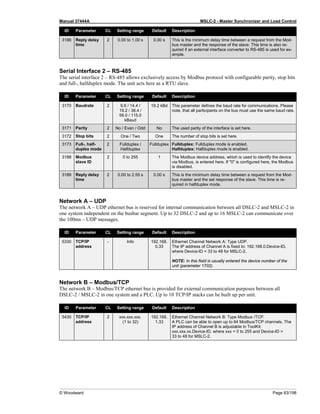
Middle Voltage System 20 kV - 3-Phase without Neutral
• Phase rotation clockwise
• System A measurement: 3-Phase PT “Open Delta”
• System B measurement: 1-Phase PT L1-L2
Figure 4-12: Middle voltage system 20 kV – 3-phase without neutral
Configuration Measurement Voltage Monitoring
Menu 5
• System A rated voltage (parameter 1766): “20000 V”
• System A current input (parameter 1850): “L1 L2 L3”
• System A voltage measuring (parameter 1851): “3Ph 3W”
• System B rated voltage (parameter 1781): “20000 V”
• 1Ph2W voltage input (parameter 1858): “Phase – phase”
• 1Ph2W phase rotation (parameter 1859): “CW”
• Auxiliary Sytem B available (parameter 7629): “No”
Transformer
• System A PT primary rated voltage (parameter 1801): “20000 V”
• System A PT secondary rated volt. (parameter 1800): “115 V”
• System B PT primary rated voltage (parameter 1804): “20000 V”
• System B PT secondary rated volt. (parameter 1803): “115 V”
• Systen A [V] L1-L2
• Systen A [V] L2-L3
• Systen A [V] L3-L1
• Systen A [A] L1
• Systen A [A] L2
• Systen A [A] L3
• Systen A [kW]
• Systen A [KVA]
• Systen A [kvar]
• Systen A [PF] L1
• Systen A [PF] L2
• Systen A [PF] L3
• Systen A [Hz]
• Systen A Phase rota-
tion
• System B [V] L1-L2
• System B [Hz]
• Phase-Angle
• System B-A
• System A [V] L1-L2
• System A [V] L2-L3
• System A [V] L3-L1
Table 4-11: Middle voltage system 20 kV – 3-phase without neutral](https://image.slidesharecdn.com/mslc-2product-manualen2017-221130120114-3cc49481/85/MSLC-2_PRODUCT-MANUAL_EN_2017-pdf-134-320.jpg)
![Manual 37444A MSLC-2 - Master Synchronizer and Load Control
© Woodward Page 135/198
Middle Voltage System 20 kV - 3-Phase without Neutral
• Phase rotation clockwise
• System A measurement: 3-Phase PT “Open Delta”
• System B measurement: 1-Phase PT L1-L2
• Auxiliary system B measurement: 3-Phase PT “Open Delta”
Figure 4-13: Middle voltage system 20 kV – 3-phase without neutral
Configuration Measurement Voltage Monitoring
Menu 5
• System A rated voltage (parameter 1766): “20000 V”
• System A current input (parameter 1850): “L1 L2 L3”
• System A voltage measuring (parameter 1851): “3Ph 3W”
• System B rated voltage (parameter 1781): “20000 V”
• 1Ph2W voltage input (parameter 1858): “Phase – phase”
• 1Ph2W phase rotation (parameter 1859): “CW”
• Auxiliary Sytem B available (parameter 7629): “Yes”
• Aux System B voltage measuring (parameter 1853): “3Ph 3W”
Transformer
• System A PT primary rated voltage (parameter 1801): “20000 V”
• System A PT secondary rated volt. (parameter 1800): “115 V”
• System B PT primary rated voltage (parameter 1804): “20000 V”
• System B PT secondary rated volt. (parameter 1803): “115 V”
• Systen A [V] L1-L2
• Systen A [V] L2-L3
• Systen A [V] L3-L1
• Systen A [A] L1
• Systen A [A] L2
• Systen A [A] L3
• Systen A [kW]
• Systen A [KVA]
• Systen A [kvar]
• Systen A [PF] L1
• Systen A [PF] L2
• Systen A [PF] L3
• Systen A [Hz]
• Systen A Phase rotation
• System B [V] L1-L2
• System B [Hz]
• Phase-Angle
• System B-A
• Aux System B [V] L1-L2
• Aux System B [V] L2-L3
• Aux System B [V] L3-L1
• Aux System B phase ro-
tation
• Aux System B [Hz]
• System A [V] L1-L2
• System A [V] L2-L3
• System A [V] L3-L1
Table 4-12: Middle voltage system 20 kV – 3-phase without neutral](https://image.slidesharecdn.com/mslc-2product-manualen2017-221130120114-3cc49481/85/MSLC-2_PRODUCT-MANUAL_EN_2017-pdf-135-320.jpg)

![Manual 37444A MSLC-2 - Master Synchronizer and Load Control
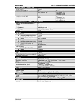
Page 174/198 © Woodward
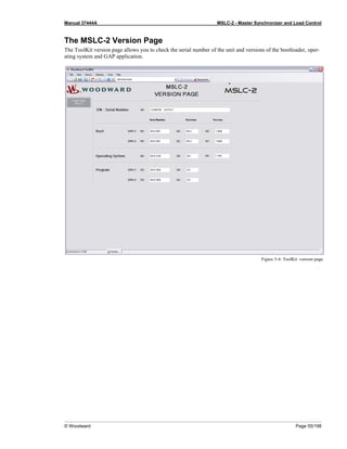
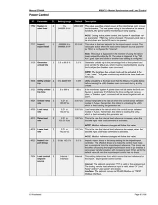
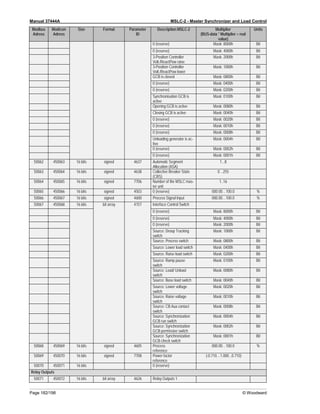
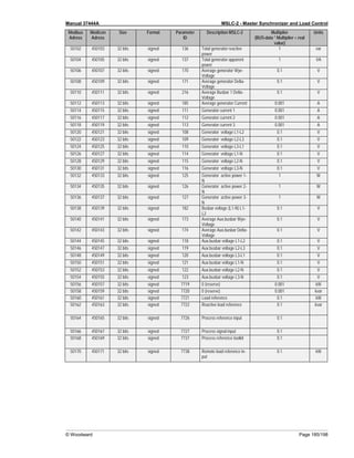
Appendix A.
Technical Data
Nameplate
1 P/N Item number
2 REV Item revision number
3 S/N Serial number (numerical)
4 S/N Serial number (barcode)
5 S/N Date of production (year-month)
6 Type Description (short)
7 Type Description (long)
8 Details Technical data
9 Approval Approvals
Measuring values (voltages) – delta-wye voltage
Measuring voltages 120 V 480 V
• Rated value (Vrated) 69/120 Vac 277/480 Vac
• Maximum value (Vmax) Max. 86/150 Vac Max. 346/600 Vac
• Rated voltage phase – ground 150 Vac 300 Vac
• Rated surge voltage 2.5 kV 4.0 kV
Linear measuring range 1.25 × Vrated
Measuring frequency 50/60 Hz (40.0 to 85.0 Hz)
Accuracy Class 0.5
Input Resistance per path 120V → 0.498 MΩ 480 V → 2.0 MΩ
Maximum power consumption per path < 0.15 W
Measuring values (currents) – isolated
Measuring current [1] Rated value (Irated) → ../1 A [5] Rated value (Irated) → ../5 A
Accuracy Class 0.5
Linear measuring range 1.5 × Irated
Maximum power consumption per path < 0.15 VA
Rated short-time current (1 s) [1] → 50.0 × Irated [5] → 10.0 × Irated
Ambient variables
Power supply 12/24 Vdc (8 to 40 Vdc)
Intrinsic consumption Max. 15W
Insulation voltage (continuously) 40 Vac
Insulation test voltage (1 s) 100 Vac
Overvoltage (≤ 2 min) 80 Vdc
Reverse voltage protection Full supply range
Grounding supply voltage source Isolated, negative potential or positive potential grounded
Degree of pollution 2
Maximum elevation 2000 m ASL
Discrete inputs – isolated
Input range (Vcont. dig. input) Rated voltage 12/24 Vdc (8 to 40.0 Vdc)
Input resistance Approx. 20 kΩ](https://image.slidesharecdn.com/mslc-2product-manualen2017-221130120114-3cc49481/85/MSLC-2_PRODUCT-MANUAL_EN_2017-pdf-174-320.jpg)
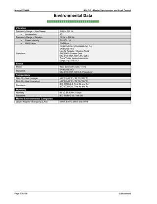
![Manual 37444A MSLC-2 - Master Synchronizer and Load Control
© Woodward Page 191/198
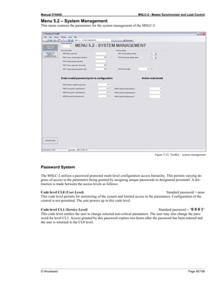
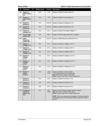
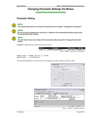
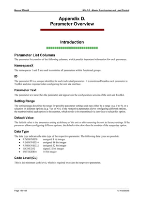
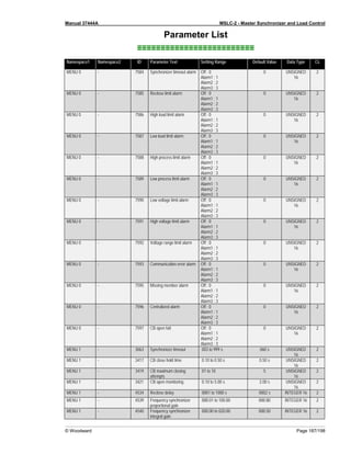
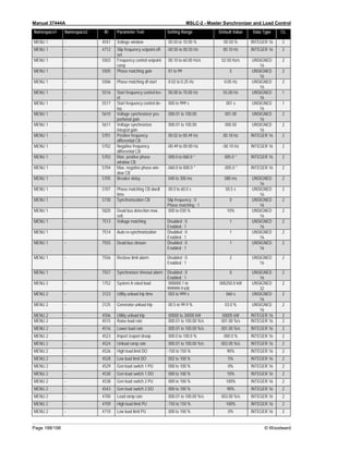
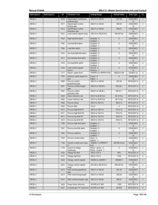
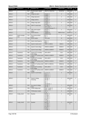
Namespace1 Namespace2 ID Parameter Text Setting Range Default Value Data Type CL
MENU 5 Config_Serial2 3171 Parity No ; 0
Even ; 1
Odd ; 2
0 UNSIGNED
16
2
MENU 5 Config_Serial2 3172 Stop bits One ; 0
Two ; 1
0 UNSIGNED
16
2
MENU 5 Config_Serial2 3173 Full-, halfduplex mode Halfduplex ; 0
Fullduplex ; 1
1 UNSIGNED
16
2
MENU 5 - 3181 Power [W] exponent
10^x
02 to 05 3 INTEGER 16 2
MENU 5 - 3182 Voltage [V] exponent 10^x -01 to 02 0 INTEGER 16 2
MENU 5 - 3183 Current [A] exponent 10^x -01 to 00 0 INTEGER 16 2
MENU 5 Config_Serial1 3185 Modbus slave ID 000 to 255 1 UNSIGNED
16
2
MENU 5 Config_Serial1 3186 Reply delay time 0.00 to 1.00 s 0.00 s UNSIGNED
16
2
MENU 5 Config_Serial2 3188 Modbus slave ID 000 to 255 1 UNSIGNED
16
2
MENU 5 Config_Serial2 3189 Reply delay time 0.00 to 2.55 s 0.00 s UNSIGNED
16
2
MENU 5 - 4544 Basic segment number 00001 to 00008 1 INTEGER 16 2
MENU 5 - 4707 Number of MSLC
communicating
00001 to 00016 1 INTEGER 16 2
MENU 5 - 4708 Number of DSLC
communicating
00000 to 00032 0 INTEGER 16 2
MENU 5 Network B 5430 TCP/IP address 0 000 to 255 192 UNSIGNED
16
2
MENU 5 Network B 5431 TCP/IP address 1 000 to 255 168 UNSIGNED
16
2
MENU 5 Network B 5432 TCP/IP address 2 000 to 255 1 UNSIGNED
16
2
MENU 5 Network B 5433 TCP/IP address 3 000 to 255 33 UNSIGNED
16
2
MENU 5 - 5800 Upper voltage limit 100 to 150 % 110% UNSIGNED
16
2
MENU 5 - 5801 Lower voltage limit 050 to 100 % 90% UNSIGNED
16
2
MENU 5 - 5802 Upper frequency limit 100.0 to 150.0 % 110.0 % UNSIGNED
16
2
MENU 5 - 5803 Lower frequency limit 050.0 to 100.0 % 090.0 % UNSIGNED
16
2
MENU 5 - 7624 Smaller segment at mea-
surement
System A ; 0
System B ; 1
0 UNSIGNED
16
2
MENU 5 Tie 7625 Switch dead bus A -> dead
bus B
No ; 0
Yes ; 1
1 UNSIGNED
16
2
MENU 5 - 7626 Switch alive bus A -> dead
bus B
No ; 0
Yes ; 1
1 UNSIGNED
16
2
MENU 5 Tie 7627 Switch alive bus B -> dead
bus A
No ; 0
Yes ; 1
1 UNSIGNED
16
2
MENU 5 - 7628 Type of MSLC breaker Tie ; 0
Utility ; 1
1 UNSIGNED
16
2
MENU 5 - 7649 Auxiliary system B
available
No ; 0
Yes ; 1
0 UNSIGNED
16
2
MENU 5 System manage-
ment
10401 Password for serial
interface1
0000 to 9999 1805 UNSIGNED
16
0
MENU 5 System manage-
ment
10404 Password for remote con-
fig.
0000 to 9999 1805 UNSIGNED
16
0
MENU 5 System manage-
ment
10411 Supercommissioning
level code
0000 to 9999 UNSIGNED
16
5](https://image.slidesharecdn.com/mslc-2product-manualen2017-221130120114-3cc49481/85/MSLC-2_PRODUCT-MANUAL_EN_2017-pdf-191-320.jpg)
![Manual 37444A MSLC-2 - Master Synchronizer and Load Control
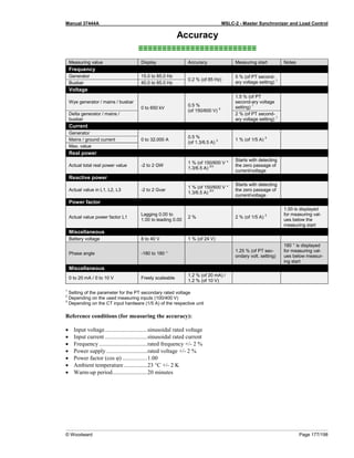
Page 194/198 © Woodward
Packing A Control
Use the following materials when returning a complete control:
• protective caps on any connectors;
• antistatic protective bags on all electronic modules;
• packing materials that will not damage the surface of the unit;
• at least 100 mm (4 inches) of tightly packed, industry-approved packing material;
• a packing carton with double walls;
• a strong tape around the outside of the carton for increased strength.
Return Authorization Number RAN
When returning equipment to Woodward, please telephone and ask for the Customer Service Department in
Stuttgart [+49 (0) 711 789 54-0]. They will help expedite the processing of your order through our distributors or
local service facility. To expedite the repair process, contact Woodward in advance to obtain a Return Authoriza-
tion Number and arrange for issue of a purchase order for the unit(s) to be repaired. No work can be started until
a purchase order is received.
NOTE
We highly recommend that you make arrangement in advance for return shipments. Contact a
Woodward customer service representative at +49 (0) 711 789 54-0 for instructions and for a Re-
turn Authorization Number.
Replacement Parts
≡≡≡≡≡≡≡≡≡≡≡≡≡≡≡≡≡≡≡≡≡≡≡≡≡
When ordering replacement parts for controls, include the following information:
• the part numbers P/N (XXXX-XXX) that is on the enclosure nameplate;
• the unit serial number S/N, which is also on the nameplate.](https://image.slidesharecdn.com/mslc-2product-manualen2017-221130120114-3cc49481/85/MSLC-2_PRODUCT-MANUAL_EN_2017-pdf-194-320.jpg)
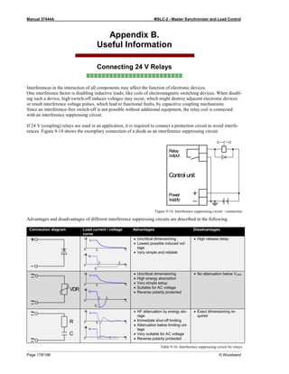
![Manual 37444A MSLC-2 - Master Synchronizer and Load Control
© Woodward Page 195/198
How To Contact Woodward
≡≡≡≡≡≡≡≡≡≡≡≡≡≡≡≡≡≡≡≡≡≡≡≡≡
Please contact following address if you have questions or if you want to send a product for repair:
Woodward GmbH
Handwerkstrasse 29
70565 Stuttgart - Germany
Phone: +49 (0) 711 789 54-0 (8.00 - 16.30 German time)
Fax: +49 (0) 711 789 54-100
e-mail: stgt-info@woodward.com
For assistance outside Germany, call one of the following international Woodward facilities to obtain the address
and phone number of the facility nearest your location where you will be able to get information and service.
Facility Phone number
USA +1 (970) 482 5811
India +91 (129) 409 7100
Brazil +55 (19) 3708 4800
Japan +81 (476) 93 4661
The Netherlands +31 (23) 566 1111
You can also contact the Woodward Customer Service Department or consult our worldwide directory on
Woodward’s website (www.woodward.com) for the name of your nearest Woodward distributor or service facil-
ity. [For worldwide directory information, go to www.woodward.com/ic/locations.]](https://image.slidesharecdn.com/mslc-2product-manualen2017-221130120114-3cc49481/85/MSLC-2_PRODUCT-MANUAL_EN_2017-pdf-195-320.jpg)