This document discusses the design of a parallel BCH encoder for satellite transmitters. Key points:
1) It proposes a new parallel algorithm for BCH encoding to increase throughput while meeting ASIC requirements for space systems.
2) The algorithm models BCH encoding as a linear system and exploits regularities in the state transition matrix to parallelize encoding.
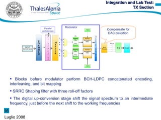
3) A prototype parallel BCH encoder was designed and integrated with an LDPC encoder. Lab tests showed the modulator achieved low error vector magnitude at transmission rates up to 30 MBaud.


![Algorithm at Higher Throughput:
Linear System Modeling
[ ] []
State equation
g0 1
g1 0
x (i )=A x (i +1)+b u (i )
b= ⋮ b= 0
⋮ ⋮
g n−k −2 ⋮
[ ]
g n−k −1 0
0 0 … 0 g0
1 0 … 0 g1
Input-state transition
A= ⋮ 1 … 0 g2 vectors
0 ⋮ ⋱ … ⋮
0 0 … 1 g r−1 The state matrix is relevant to
the system itself and so is common
to both system
State transition matrix: It
models its evolution I-S Vectors change as input
position changes
9
Luglio 2008](https://image.slidesharecdn.com/dvbbch-110509163009-phpapp01/85/MSc-Presentation-9-320.jpg)
![System Parallelization
By applying the following This matrix shows some sort
recursive substitution of regularity
x (i )=A x (i −1)+b u (i −1)
x (i −1)=A x (i −2)+b u (i together
Putting −2) p
Ap=
( 0 C1
I C2 )
column vectors
p: parallelismo )
(b Ab L A p −1 b It is common to both
system
p−1
x (i )=A x (i −p )+ ∑ A k b u (i −k −1)
p
k =0
Bp= I
0 () LFSR
x (ip)=A p x [(i −1) p ]+B p u (ip)
Bp Serial encoder
10
Luglio 2008](https://image.slidesharecdn.com/dvbbch-110509163009-phpapp01/85/MSc-Presentation-10-320.jpg)


![1.[1 6] a novel papr reduction scheme based on selective mapping and a random...](https://cdn.slidesharecdn.com/ss_thumbnails/1-1-6anovelpaprreductionschemebasedonselectivemappingandarandom-likecodingwithnoexplicitsideinformationinofdm-111118182659-phpapp02-thumbnail.jpg?width=640&height=640&fit=bounds)
![1.[1 6] a novel papr reduction scheme based on selective mapping and a random...](https://cdn.slidesharecdn.com/ss_thumbnails/1-1-6anovelpaprreductionschemebasedonselectivemappingandarandom-likecodingwithnoexplicitsideinformationinofdm-111118181640-phpapp01-thumbnail.jpg?width=640&height=640&fit=bounds)
![1.[1 6] a novel papr reduction scheme based on selective mapping and a random...](https://cdn.slidesharecdn.com/ss_thumbnails/1-1-6anovelpaprreductionschemebasedonselectivemappingandarandom-likecodingwithnoexplicitsideinformationinofdm-111203184830-phpapp01-thumbnail.jpg?width=640&height=640&fit=bounds)


