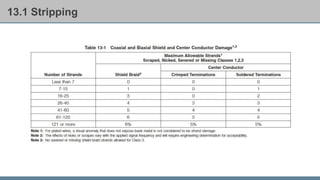
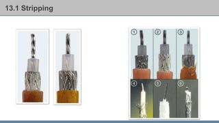
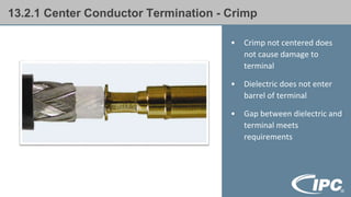
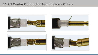
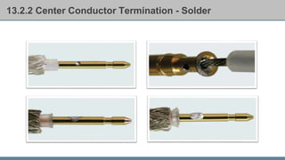
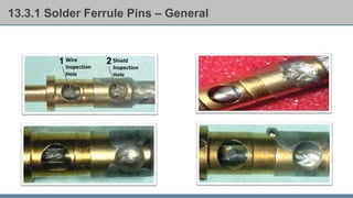
IPC/WHMA-A-620D
“Requirements and Acceptance for Cable and Wire
Harness Assemblies”
Module 7: Coaxial and Biaxial Cable Assemblies
Module Objective
Identify coaxial and biaxial cable assemblies
requirements and criteria
Module Overview
Coaxial and Biaxial Cable Assemblies (Section 13)
Section Overview
Stripping
Center Conductor Termination
Solder Ferrule Pins
Coaxial Connector
Shield Termination
Center Pin
Semirigid Coax
Swage-Type Connector
Soldering and Stripping of Biaxial/ Multi-Axial Shielded Wire
13 Coaxial and Biaxial Cable Assemblies
• Follow connector
manufacturer assembly
instructions
• Pieces must be concentric
as possible
• Outer diameter, dielectric
thickness and inside
diameter are critical
elements
• Insulation integrity
13.1 Stripping
• Coaxial cable is
manufactured using
different shield
configuration
• Double shield cable
with a foil wrap rather
than a second braid :
⁻ Foil is not used for
mechanical attachment
⁻ Assembled as a single
braid cable
13.1 Stripping
13.1 Stripping
13.1 Stripping
13.2 Center Conductor Termination
13.2.1 Center Conductor Termination - Crimp
• Crimp not centered does
not cause damage to
terminal
• Dielectric does not enter
barrel of terminal
• Gap between dielectric and
terminal meets
requirements
13.2.1 Center Conductor Termination - Crimp
13.2.2 Center Conductor Termination - Solder
13.3.1 Solder Ferrule Pins – General
Wire
Inspection
Hole
Shield
Inspection
Hole
13.3.2 Solder Ferrule Pins - Insulation
Apply what you learned
Insulation in the inspection hole of a solder ferrule pin protruding beyond the pin surface and
does not prevent contact mating. For a Class 3 product this condition is considered?
Acceptable Not Specified
Process Indicator Defect
Apply what you learned
Solder slightly protrudes from inspection window of a soldered center conductor termination
but does not interfere with assembly. This condition is considered?
Acceptable Not Specified
Process Indicator Defect
Apply what you learned
Any damage to the coaxial cable that does not exceed the limits of Table 13-1, for Class 2 & 3
products is considered?
Acceptable Not Specified
Process Indicator Defect

Modulo 7 IPC 620.pptx

  • 1.
    IPC/WHMA-A-620D “Requirements and Acceptancefor Cable and Wire Harness Assemblies” Module 7: Coaxial and Biaxial Cable Assemblies
  • 2.
    Module Objective Identify coaxialand biaxial cable assemblies requirements and criteria
  • 3.
    Module Overview Coaxial andBiaxial Cable Assemblies (Section 13)
  • 4.
    Section Overview Stripping Center ConductorTermination Solder Ferrule Pins Coaxial Connector Shield Termination Center Pin Semirigid Coax Swage-Type Connector Soldering and Stripping of Biaxial/ Multi-Axial Shielded Wire
  • 5.
    13 Coaxial andBiaxial Cable Assemblies • Follow connector manufacturer assembly instructions • Pieces must be concentric as possible • Outer diameter, dielectric thickness and inside diameter are critical elements • Insulation integrity
  • 6.
    13.1 Stripping • Coaxialcable is manufactured using different shield configuration • Double shield cable with a foil wrap rather than a second braid : ⁻ Foil is not used for mechanical attachment ⁻ Assembled as a single braid cable
  • 7.
  • 8.
  • 9.
  • 10.
  • 11.
    13.2.1 Center ConductorTermination - Crimp • Crimp not centered does not cause damage to terminal • Dielectric does not enter barrel of terminal • Gap between dielectric and terminal meets requirements
  • 12.
    13.2.1 Center ConductorTermination - Crimp
  • 13.
    13.2.2 Center ConductorTermination - Solder
  • 14.
    13.3.1 Solder FerrulePins – General Wire Inspection Hole Shield Inspection Hole
  • 15.
    13.3.2 Solder FerrulePins - Insulation
  • 16.
    Apply what youlearned Insulation in the inspection hole of a solder ferrule pin protruding beyond the pin surface and does not prevent contact mating. For a Class 3 product this condition is considered? Acceptable Not Specified Process Indicator Defect
  • 17.
    Apply what youlearned Solder slightly protrudes from inspection window of a soldered center conductor termination but does not interfere with assembly. This condition is considered? Acceptable Not Specified Process Indicator Defect
  • 18.
    Apply what youlearned Any damage to the coaxial cable that does not exceed the limits of Table 13-1, for Class 2 & 3 products is considered? Acceptable Not Specified Process Indicator Defect

Editor's Notes

  • #3 Instructor Guide; Upon completion of this Module, the participant will be able to identify the requirements and acceptance criteria for coaxial and biaxial cable assemblies, as described in IPC/WHMA-A-620D standard and show the ability to navigate and locate the criteria in the standard through knowledge checks and exercises.
  • #4 Instructor Guide: This module is comprised of the following section of the IPC/WHMA-A-620D standard: Section 13: Coaxial and Biaxial Cable Assemblies
  • #5 Instructor Guide: In this module we will discuss: Stripping Center Conductor Termination Solder Ferrule Pins Coaxial Connector Shield Termination Center Pin Semirigid Coax Swage-Type Connector Soldering and Stripping of Biaxial Wire/Multi-Axial Shielded Wire
  • #6 Instructor Guide: This slide has a video clip. Follow all assembly instructions provided by the connector manufacturer. For nonstandard applications, process design verification should be performed. Pieces of the connectors must remain as concentric as possible. Concentric means all the circles share the same center point. The distance from the outer metal layer (shield) and the inner metal layer (conductor) is vital for the correct functioning of the cable. The distance between two conductors determines capacitance. If the distance is changed (e.g., kinked coax, bad cut of semi-rigid tubing) it will modify/change the capacitance. Any modification/change of the capacitance will affect the function (e.g., lose data). Insulation integrity is important to preclude shorting of shields to each other or shorting of shields to the center conductor.
  • #7 Instructor Guide: Coaxial cable is manufactured using different shield configurations that give different percentage of coverage values. The majority of cable fits into just a few groups. Some cable is identified as double shield. When the double shield has a foil wrap rather than a second braid, the foil is not used during mechanical attachment and would be assembled as a single-braid cable.
  • #8 Instructor Guide: Tolerance of a shield configuration to missing strands depends on the shield coverage percentage required. Table 13-1 provides the damaged or missing braid allowances. This table is similar to the wire damage table, Table 3-1. The columns are split by type of conductor (shielded braid and then crimped/soldered center conductor). Pay attention to the notes and where each note applies.
  • #9 Instructor Guide; Acceptable – Class 1,2,3 Slight marks on dielectric. Minor unraveling of braid. Defect – Class 1,2,3 1. Braid twisted. 2. Braid scored. 3. Outer jacket frayed. 4. Unwoven braid, missing strands. 5. Ragged dielectric, tool marks. 6. Incomplete removal of strands.
  • #10 Instructor Guide: Acceptable – Class 1,2,3 Trim area offset does not exceed 10% of the cable diameter (D) beyond the perpendicular angle to the center conductor. Not Established – Class 1, Defect – Class 2,3 Trim area offset exceeds 10% of the cable diameter (D) beyond the perpendicular angle to the center conductor.
  • #11 Instructor Guide: Play video clip
  • #12 Instructor Guide; As an exception to crimping criteria of 5 (Crimp Terminations (Controls and Lugs)) introduction, crimping of solid wire is acceptable when the connector is designed for solid wire and the connection is performed in accordance with the connector manufacturer’s procedures and recommended tooling. Acceptable – Class 1,2,3 Crimp not centered on crimp area of terminal but does not cause damage to terminal. Dielectric does not enter barrel of terminal. Gap between dielectric and terminal meets manufacturer’s requirements. In the absence of manufacturer’s specifications, there is no gap.
  • #13 Instructor Guide: Defect – Class 1,2,3 Crimp not centered and causes damage to terminal (top left image). Strand not captured (top right image). Pin shows ‘‘dog ear’’ of excess material (bottom left image). Terminal damaged by crimp (bottom right image).
  • #14 Instructor Guide: Acceptable – Class 1,2,3 The inspection window is filled with solder (top left image). Solder slightly protrudes from inspection window but will not interfere with assembly. Minor flare of dielectric due to heat from solder does not interfere with assembly of connector (bottom left image). Defect – Class 1,2,3 Solder not visible in inspection window. No discernible solder fillet or wetting between terminal and conductor (top right image). Excess solder prevents proper assembly of connector and electrical impedance of the connector. Damage to dielectric due to heat from solder (bottom right image).
  • #15 Instructor Guide: Acceptable – Class 1,2,3 Twist of center conductor is disturbed (top left image-1). Solder fillet is evident in inspection holes. Film of solder on outside of terminal that does not interfere with subsequent assembly operations (bottom left image). Defect – Class 1,2,3 Shield strand is protruding through sleeving or out of inspection hole (top right image). Solder buildup on outside surface of contact. Film of solder on outside of terminal interferes with subsequent assembly operations (bottom right image).
  • #16 Instructor Guide: Acceptable – Class 1,2, Process Indicator – Class 3 Insulation in inspection hole is protruding beyond the pin surface but does not prevent contact mating. Defect – Class 1,2,3 Insulation has melted beyond the outside surface of contact and contact hole is obstructed (A). Insulation in inspection hole is protruding beyond the pin surface, prevents contact mating (B).
  • #17 Insulation in the inspection hole of a solder ferrule pin protruding beyond the pin surface and does not prevent contact mating. For a Class 3 product this condition is considered? Acceptable Not Specified Process Indicator Defect Clause 13.3.2
  • #18 Solder slightly protrudes from inspection window of a soldered center conductor termination but does not interfere with assembly. This condition is considered? Acceptable Not Specified Process Indicator Defect Clause 13.2.2
  • #19 Any damage to the coaxial cable that does not exceed the limits of Table 13-1, for Class 2 & 3 products is considered? Acceptable Not Specified Process Indicator Defect Clause 13.1