Introduction
Computers arebuilt using logic circuits
that operate on information
represented by two- valued
electrical signals
Labelled as 0 and 1
We define the amount of information
represented by such a signal as a bit of
information, where bit stands for binary
digit.
The most natural way to represent a
5.
Number Representation
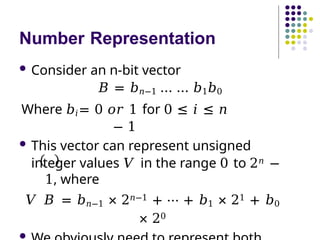
Consideran n-bit vector
𝐵 = 𝑏𝑛−1 … … 𝑏1𝑏0
Where 𝑏𝑖= 0 𝑜𝑟 1 for 0 ≤ 𝑖 ≤ 𝑛
− 1
This vector can represent unsigned
integer values 𝑉 in the range 0 to 2𝑛 −
1, where
𝑉 𝐵 = 𝑏𝑛−1 × 2𝑛−1 + ⋯ + 𝑏1 × 21 + 𝑏0
× 20
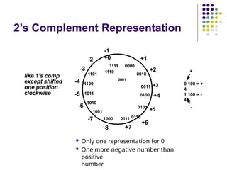
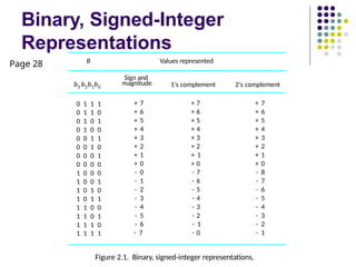
6.
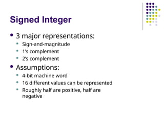
Signed Integer
3major representations:
Sign-and-magnitude
1’s complement
2’s complement
Assumptions:
4-bit machine word
16 different values can be represented
Roughly half are positive, half are
negative
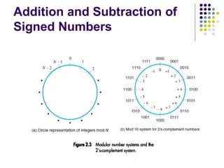
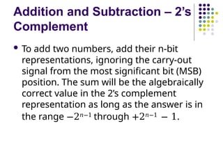
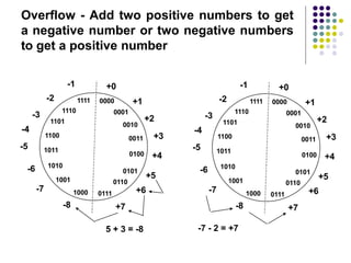
Addition and Subtraction– 2’s
Complement
To add two numbers, add their n-bit
representations, ignoring the carry-out
signal from the most significant bit (MSB)
position. The sum will be the algebraically
correct value in the 2’s complement
representation as long as the answer is in
the range −2𝑛−1 through +2𝑛−1 − 1.
14.
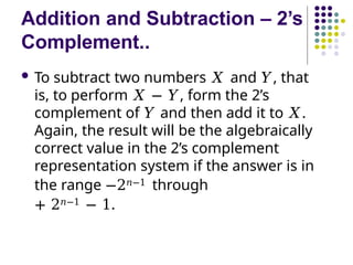
Addition and Subtraction– 2’s
Complement..
To subtract two numbers 𝑋 and 𝑌, that
is, to perform 𝑋 − 𝑌, form the 2’s
complement of 𝑌 and then add it to 𝑋.
Again, the result will be the algebraically
correct value in the 2’s complement
representation system if the answer is in
the range −2𝑛−1 through
+ 2𝑛−1 − 1.
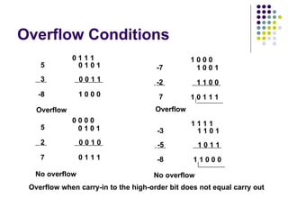
15.
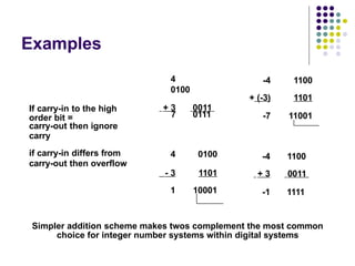
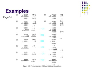
Examples
4
0100
+ 3 0011
Ifcarry-in to the high
carry-out then ignore
7 0111
if carry-in differs from 4 0100
- 3 1101
1 10001
-4 1100
+ (-3) 1101
-7 11001
-4 1100
+ 3 0011
-1 1111
order bit =
carry
carry-out then overflow
Simpler addition scheme makes twos complement the most common
choice for integer number systems within digital systems
Characters
In additionto numbers, computers
must be able to handle nonnumeric
text information consisting of
characters.
Characters can be letters of the alphabet,
decimal digits, punctuation marks, and so
on.
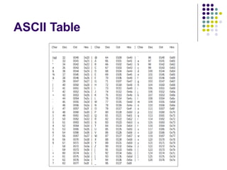
They are represented by codes that
are usually eight bits long.
American Standards Committee on
Information Interchange (ASCII) code is
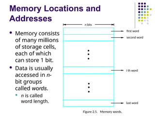
Memory Locations and
Addresses
Memory consists
of many millions
of storage cells,
each of which
can store 1 bit.
Data is usually
accessed in n-
bit groups
called words.
n is called
word length.
second word
first word
Figure 2.5. Memory words.
n bits
last word
i th word
•
•
•
•
•
•
23.
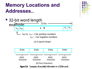
Memory Locations and
Addresses..
32-bit word length
example
(b) Four characters
ASCII
character
ASCII
character
ASCII
character
ASCII
character
Sign bit: b31= 0 for positive numbers
b31= 1 for negative numbers
(a) A signed integer
32 bits
8 bits 8 bits 8 bits 8 bits
•
b31 b30
•
•
b1 b0
24.
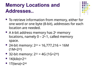
Memory Locations and
Addresses..
To retrieve information from memory, either for
one word or one byte (8-bit), addresses for each
location are needed.
A k-bit address memory has 2k memory
locations, namely 0 – 2k-1, called memory
space.
24-bit memory: 224 = 16,777,216 = 16M
(1M=220)
32-bit memory: 232 = 4G (1G=230)
1K(kilo)=210
1T(tera)=240
25.
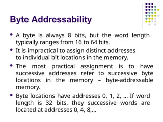
Byte Addressability
Abyte is always 8 bits, but the word length
typically ranges from 16 to 64 bits.
It is impractical to assign distinct addresses
to individual bit locations in the memory.
The most practical assignment is to have
successive addresses refer to successive byte
locations in the memory – byte-addressable
memory.
Byte locations have addresses 0, 1, 2, … If word
length is 32 bits, they successive words are
located at addresses 0, 4, 8,…
26.
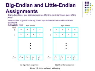
Big-Endian and Little-Endian
Assignments
01 2 3
4 5 6 7
•
•
•
k
2 - 4
k
2 - 3
k
2 -
2
k
2 -
1
k
2 - 4
k
2 - 4
0
0
4
3 2 1 0
7 6 5 4
•
•
•
k
2 -
1
k
2 -
2
k
2 - 3
k
2 -
4
Byte address Byte address
(a) Big-endian assignment (b) Little-endian assignment
Figure 2.7. Byte and word addressing.
4
address
Big-Endian: lower byte addresses are used for the most significant bytes of the
word
Little-Endian: opposite ordering. lower byte addresses are used for the less
significant
bytes of the word
Word
27.
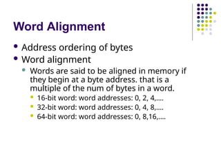
Word Alignment
Addressordering of bytes
Word alignment
Words are said to be aligned in memory if
they begin at a byte address. that is a
multiple of the num of bytes in a word.
16-bit word: word addresses: 0, 2, 4,….
32-bit word: word addresses: 0, 4, 8,….
64-bit word: word addresses: 0, 8,16,….
28.
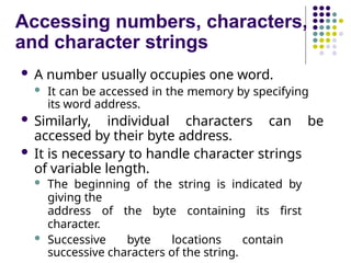
Accessing numbers, characters,
andcharacter strings
A number usually occupies one word.
It can be accessed in the memory by specifying
its word address.
Similarly, individual characters can be
accessed by their byte address.
It is necessary to handle character strings
of variable length.
The beginning of the string is indicated by
giving the
address of the byte containing its first
character.
Successive byte locations contain
successive characters of the string.
29.
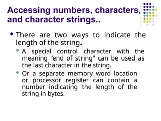
Accessing numbers, characters,
andcharacter strings..
There are two ways to indicate the
length of the string.
A special control character with the
meaning "end of string" can be used as
the last character in the string.
Or a separate memory word location
or processor register can contain a
number indicating the length of the
string in bytes.
30.
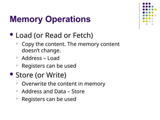
Memory Operations
Load(or Read or Fetch)
Copy the content. The memory content
doesn’t change.
Address – Load
Registers can be used
Store (or Write)
Overwrite the content in memory
Address and Data – Store
Registers can be used
31.
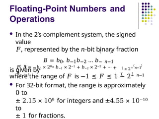
Floating-Point Numbers and
Operations
In the 2’s complement system, the signed
value
𝐹, represented by the 𝑛-bit binary fraction
𝐵 = 𝑏0. 𝑏−1𝑏−2 … 𝑏− 𝑛−1
is given by
𝐹 𝐵 = −𝑏0 × 20+ 𝑏−1 × 2−1 + 𝑏−2 × 2−2 + ⋯ +
𝑏− 𝑛−1
× 2− 𝑛−1
where the range of 𝐹 is −1 ≤ 𝐹 ≤ 1 − 2− 𝑛−1
For 32-bit format, the range is approximately
0 to
± 2.15 × 10⁹ for integers and ±4.55 × 10⁻¹⁰
to
± 1 for fractions.
32.
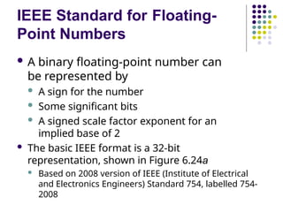
IEEE Standard forFloating-
Point Numbers
A binary floating-point number can
be represented by
A sign for the number
Some significant bits
A signed scale factor exponent for an
implied base of 2
The basic IEEE format is a 32-bit
representation, shown in Figure 6.24a
Based on 2008 version of IEEE (Institute of Electrical
and Electronics Engineers) Standard 754, labelled 754-
2008
34.
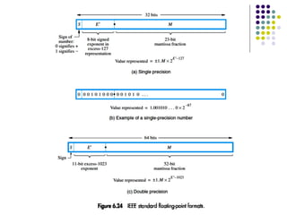
IEEE Standard forFloating-
Point Numbers..
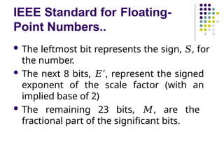
The leftmost bit represents the sign, 𝑆, for
the number.
The next 8 bits, 𝐸′, represent the signed
exponent of the scale factor (with an
implied base of 2)
The remaining 23 bits, 𝑀, are the
fractional part of the significant bits.
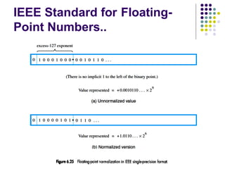
35.
IEEE Standard forFloating-
Point Numbers..
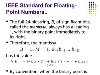
The full 24-bit string, B, of significant bits,
called the mantissa, always has a leading
1, with the binary point immediately to
its right.
Therefore, the mantissa
𝐵 = 1. 𝑀 = 1. 𝑏−1𝑏−2 … 𝑏−23
has the value
V 𝐵 = 1+ 𝑏−1 × 2−1 + 𝑏−2 × 2−2 + ⋯ + 𝑏−23 ×
2−23
By convention, when the binary point is
36.
IEEE Standard forFloating-
Point Numbers..
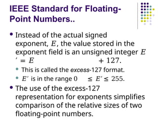
Instead of the actual signed
exponent, 𝐸, the value stored in the
exponent field is an unsigned integer 𝐸
′ = 𝐸 + 127.
This is called the excess-127 format.
𝐸′ is in the range 0 ≤ 𝐸′ ≤ 255.
The use of the excess-127
representation for exponents simplifies
comparison of the relative sizes of two
floating-point numbers.
37.
IEEE Standard forFloating-
Point Numbers..
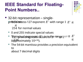
32-bit representation – single-
precision
8-bit excess-127 exponent 𝐸′ with range 1
≤
𝐸′ ≤
254 for normal values
0 and 255 indicate special values
The actual exponent, 𝐸′, is in the range
−126
≤ 𝐸′
≤
127 providing scale factors of 2−126 to 2127
(approximately 10±38).
The 54-bit mantissa provides a precision equivalent
to
about 7 decimal digits
38.
IEEE Standard forFloating-
Point Numbers..
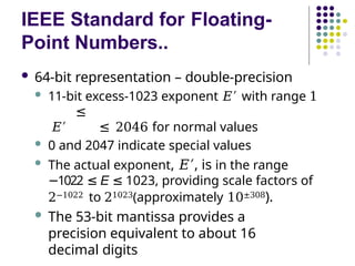
64-bit representation – double-precision
11-bit excess-1023 exponent 𝐸′ with range 1
≤
𝐸′ ≤ 2046 for normal values
0 and 2047 indicate special values
The actual exponent, 𝐸′, is in the range
1022
− ≤ E ≤ 1023, providing scale factors of
2−1022 to 21023(approximately 10±308).
The 53-bit mantissa provides a
precision equivalent to about 16
decimal digits
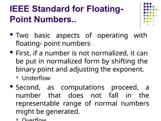
IEEE Standard forFloating-
Point Numbers..
Two basic aspects of operating with
floating- point numbers
First, if a number is not normalized, it can
be put in normalized form by shifting the
binary point and adjusting the exponent.
Underflow
Second, as computations proceed, a
number that does not fall in the
representable range of normal numbers
might be generated.
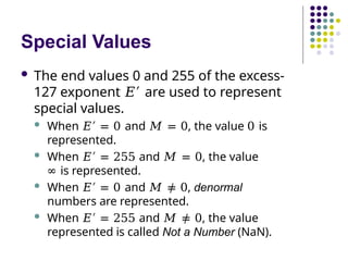
41.
Special Values
Theend values 0 and 255 of the excess-
127 exponent 𝐸′ are used to represent
special values.
When 𝐸′ = 0 and 𝑀 = 0, the value 0 is
represented.
When 𝐸′ = 255 and 𝑀 = 0, the value
∞ is represented.
When 𝐸′ = 0 and 𝑀 ≠ 0, denormal
numbers are represented.
When 𝐸′ = 255 and 𝑀 ≠ 0, the value
represented is called Not a Number (NaN).
“Must-Perform” Operations
Acomputer must have instructions
capable of performing four types of
operations:
Data transfers between the memory and
the processor registers
Arithmetic and logic operations on data
Program sequencing and control
I/O transfers
44.
Register Transfer Notation
Identify a location by a symbolic name
standing for its hardware binary address
Names for addresses of memory location may
be LOC, PLACE, A, VAR2
Processor register names may be R0, R5
I/O register names may be DATAIN,
OUTSTATUS
Contents of a location are denoted by placing
square brackets around the name of the
location
R1 [LOC]
←
R3 [R1]+[R2]
←
CPU Organization
SingleAccumulator
Result usually goes to the Accumulator
Accumulator has to be saved to memory
quite often
General Register
Registers hold operands thus reduce
memory traffic
Register bookkeeping
Stack
Operands and result are always in the
stack
47.
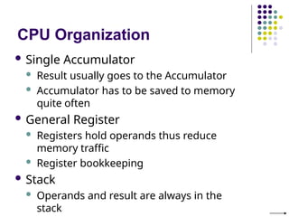
Basic Instruction Types
Three-Address Instructions
Add R1, R2, R3 R3 ← R1
+ R2
Two-Address Instructions
Add R1, R2 R2 ← R1 + R2
One-Address Instructions
Add M
Zero-Address
Instructions
Add
RISC Instructions
AC ← AC + [M]
TOS ← TOS + (TOS – 1)
Lots of registers. Memory is restricted to Load &
Store
Opcode Operand(s) or Address(es)
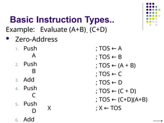
Basic Instruction Types..
Example:Evaluate (A+B) (C+D)
One-Address
1. Load
A
2. Add
B
3. Store
T
4. Load
C
5. Add
D
; AC ← A
; AC ← AC + B
; T ← AC
; AC ← [C]
; AC ← AC + [D]
; AC ← AC [T]
; X ← AC
51.
Basic Instruction Types..
Example:Evaluate (A+B) (C+D)
Zero-Address
1. Push
A
2. Push
B
3. Add
4. Push
C
5. Push
D
6. Add
X
; TOS ← A
; TOS ← B
; TOS ← (A + B)
; TOS ← C
; TOS ← D
; TOS ← (C + D)
; TOS ← (C+D)(A+B)
; X ← TOS
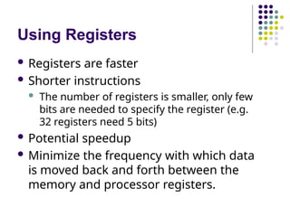
Using Registers
Registersare faster
Shorter instructions
The number of registers is smaller, only few
bits are needed to specify the register (e.g.
32 registers need 5 bits)
Potential speedup
Minimize the frequency with which data
is moved back and forth between the
memory and processor registers.
54.
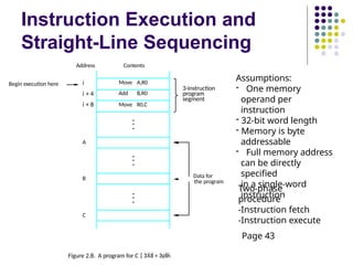
Instruction Execution and
Straight-LineSequencing
Move A,R0
Add B,R0
Move R0,C
i
i + 4
i + 8
Begin execution here
Address Contents
C
B
A
the program
Data for
3-instruction
program
segment
Figure 2.8. A program for C +
Assumptions:
- One memory
operand per
instruction
- 32-bit word length
- Memory is byte
addressable
- Full memory address
can be directly
specified
in a single-word
instruction
Two-phase
procedure
-Instruction fetch
-Instruction execute
Page 43
55.
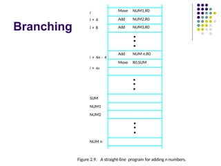
Branching
NUM n
Figure 2.9.A straight-line program for adding n numbers.
SUM
NUM1
NUM2
Move NUM1,R0
Add NUM2,R0
Add NUM3,R0
•
•
•
Add NUM n,R0
Move R0,SUM
•
•
•
•
•
•
i
i + 4n - 4
i + 4n
i + 4
i + 8
56.
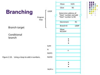
Branching
N,R1
Move
NUM n
NUM2
SUM
N
NUM1
Figure 2.10.Using a loop to add n numbers.
LOOP
Program
loop
Clear R0
Determine address of
"Next" number and add
"Next" number to R0
Decrement R1
Branch>0 LOOP
Move
R0,SUM
•
•
•
n
•
•
•
Branch target
Conditional
branch
57.
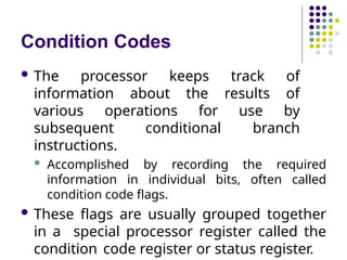
Condition Codes
Theprocessor keeps track of
information about the results of
various operations for use by
subsequent conditional branch
instructions.
Accomplished by recording the required
information in individual bits, often called
condition code flags.
These flags are usually grouped together
in a special processor register called the
condition code register or status register.
58.
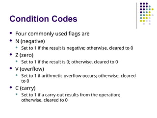
Condition Codes
Fourcommonly used flags are
N (negative)
Set to 1 if the result is negative; otherwise, cleared to 0
Z (zero)
Set to 1 if the result is 0; otherwise, cleared to 0
V (overflow)
Set to 1 if arithmetic overflow occurs; otherwise, cleared
to 0
C (carry)
Set to 1 if a carry-out results from the operation;
otherwise, cleared to 0


![Register Transfer Notation
Identify a location by a symbolic name
standing for its hardware binary address
Names for addresses of memory location may
be LOC, PLACE, A, VAR2
Processor register names may be R0, R5
I/O register names may be DATAIN,
OUTSTATUS
Contents of a location are denoted by placing
square brackets around the name of the
location
R1 [LOC]
←
R3 [R1]+[R2]
←](https://image.slidesharecdn.com/module-1b-machine-instructions-and-programs-250810044228-892a2ed5/85/MODULE-1-b-Machine-Instructions-and-Programs-pptx-44-320.jpg)
![Assembly Language Notation
Represent machine instructions
and programs.
Move LOC, R1 = R1 [LOC]
←
Add R1, R2, R3 = R3 [R1]+[R2]
←](https://image.slidesharecdn.com/module-1b-machine-instructions-and-programs-250810044228-892a2ed5/85/MODULE-1-b-Machine-Instructions-and-Programs-pptx-45-320.jpg)
![Basic Instruction Types
Three-Address Instructions
Add R1, R2, R3 R3 ← R1
+ R2
Two-Address Instructions
Add R1, R2 R2 ← R1 + R2
One-Address Instructions
Add M
Zero-Address
Instructions
Add
RISC Instructions
AC ← AC + [M]
TOS ← TOS + (TOS – 1)
Lots of registers. Memory is restricted to Load &
Store
Opcode Operand(s) or Address(es)](https://image.slidesharecdn.com/module-1b-machine-instructions-and-programs-250810044228-892a2ed5/85/MODULE-1-b-Machine-Instructions-and-Programs-pptx-47-320.jpg)
![Basic Instruction Types..
Example: Evaluate (A+B) (C+D)
Three-Address
1. Add
2. Add
3. Multipl
y
A, B, R1
C, D, R2
R1, R2, X
; R1 ← [A] + [B]
; R2 ← [C] + [D]
; X ← [R1] [R2]](https://image.slidesharecdn.com/module-1b-machine-instructions-and-programs-250810044228-892a2ed5/85/MODULE-1-b-Machine-Instructions-and-Programs-pptx-48-320.jpg)
![Basic Instruction Types..
Example: Evaluate (A+B) (C+D)
Two-Address
1. Move A, R1 ; R1 ← [A]
2. Add B, R1 ; R1 ← [R1] + [B]
3. Move C, R2 ; R2 ← [C]
4. Add D, R2 ; R2 ← [R2] + [D]
5. Multiply R1, R2 ; R2 ← [R1] [R2]
6. Move R2, X ; X ← [R2]](https://image.slidesharecdn.com/module-1b-machine-instructions-and-programs-250810044228-892a2ed5/85/MODULE-1-b-Machine-Instructions-and-Programs-pptx-49-320.jpg)
![Basic Instruction Types..
Example: Evaluate (A+B) (C+D)
One-Address
1. Load
A
2. Add
B
3. Store
T
4. Load
C
5. Add
D
; AC ← A
; AC ← AC + B
; T ← AC
; AC ← [C]
; AC ← AC + [D]
; AC ← AC [T]
; X ← AC](https://image.slidesharecdn.com/module-1b-machine-instructions-and-programs-250810044228-892a2ed5/85/MODULE-1-b-Machine-Instructions-and-Programs-pptx-50-320.jpg)
![Basic Instruction
Types..
Example: Evaluate (A+B) (C+D)
RISC
1.
Load
A, R1 ; R1 ← [A]
2.
Load
B, R2 ; R2 ← [B]
3.
Load
C, R3 ; R3 ← [C]
4.
Load
D, R4 ; R4 ← [D]
5. Add R1, R2 ; R2 ← R1 + R2
6. Add R3, R4 ; R4 ← R3 + R4
7. R2, R4 ; R4 ← R2 R4](https://image.slidesharecdn.com/module-1b-machine-instructions-and-programs-250810044228-892a2ed5/85/MODULE-1-b-Machine-Instructions-and-Programs-pptx-52-320.jpg)