Presentation on measuring magnetic property of samplePremashis Kumar
I gave this presentation during my iii semester M.Sc program.This is about experiment technique to measure magnetization.Here we discuss induction method magnetometry.
MAGNETOMETER
Outline
• Pinciples of operation of magnetometer.
• How Magnetometer works…???
• Cordinate Systems
• Types
• SQUID Magnetometer
• Applications
MAGNETOMETER – PRINCIPLES OF OPERATION
Hall Effect Magnetometer
Lorentz Force -
Benefits-
Solid-state
Low Temperature
Sensitivity
Highly Linear
Small
Cheap
Drawbacks-
Saturation limit
Calibration Issues
How Magnetometers Work..???
Coordinate Systems
TYPES OF MAGNETOMETER
SQUID MAGNETOMETER
APPLICATIONS OF MAGNETOMETER
1. They are used for navigational purposes.
2. They are used in anti-lock braking systems in vehicles.
3. Fluxgate magnetometers have been used in space missions for magnetic field measurements.
4. Magnetometers are used for mineral exploration; it is used to search world-class deposits of gold,silver, iron copper, etc.
5. They are used in many defence applications; UAVs, submarines, etc.
6. Magnetometers have found usages in smartphones which have applications that serve as compasses.
7. And many more..
THANK YOU.
MOCT (magneto optical current transformer)- presentationUjjwal Singh
Magneto Optical Current Transformer power point presentation. It is one of the nice and cool topics what you should choose in your college as a seminar topic. It is one of the best slides what you ever want to present in your college.It is one of the current topic of 2017.
Vibration and frequency measuring instrumentsPrashant thakur
This presentation is about the basic concepts of vibration & Frequency measuring instruments and their types.
The slides contains the best picture as example of the theory portion.
Vibration and frequency measuring instrumentsPrashant thakur
This presentation is about the basic concepts of vibration & Frequency measuring instruments and their types.
The slides contains the best picture as example of the theory portion.
Sachpazis:Terzaghi Bearing Capacity Estimation in simple terms with Calculati...Dr.Costas Sachpazis
Terzaghi's soil bearing capacity theory, developed by Karl Terzaghi, is a fundamental principle in geotechnical engineering used to determine the bearing capacity of shallow foundations. This theory provides a method to calculate the ultimate bearing capacity of soil, which is the maximum load per unit area that the soil can support without undergoing shear failure. The Calculation HTML Code included.
Saudi Arabia stands as a titan in the global energy landscape, renowned for its abundant oil and gas resources. It's the largest exporter of petroleum and holds some of the world's most significant reserves. Let's delve into the top 10 oil and gas projects shaping Saudi Arabia's energy future in 2024.
Final project report on grocery store management system..pdfKamal Acharya
In today’s fast-changing business environment, it’s extremely important to be able to respond to client needs in the most effective and timely manner. If your customers wish to see your business online and have instant access to your products or services.
Online Grocery Store is an e-commerce website, which retails various grocery products. This project allows viewing various products available enables registered users to purchase desired products instantly using Paytm, UPI payment processor (Instant Pay) and also can place order by using Cash on Delivery (Pay Later) option. This project provides an easy access to Administrators and Managers to view orders placed using Pay Later and Instant Pay options.
In order to develop an e-commerce website, a number of Technologies must be studied and understood. These include multi-tiered architecture, server and client-side scripting techniques, implementation technologies, programming language (such as PHP, HTML, CSS, JavaScript) and MySQL relational databases. This is a project with the objective to develop a basic website where a consumer is provided with a shopping cart website and also to know about the technologies used to develop such a website.
This document will discuss each of the underlying technologies to create and implement an e- commerce website.
Event Management System Vb Net Project Report.pdfKamal Acharya
In present era, the scopes of information technology growing with a very fast .We do not see any are untouched from this industry. The scope of information technology has become wider includes: Business and industry. Household Business, Communication, Education, Entertainment, Science, Medicine, Engineering, Distance Learning, Weather Forecasting. Carrier Searching and so on.
My project named “Event Management System” is software that store and maintained all events coordinated in college. It also helpful to print related reports. My project will help to record the events coordinated by faculties with their Name, Event subject, date & details in an efficient & effective ways.
In my system we have to make a system by which a user can record all events coordinated by a particular faculty. In our proposed system some more featured are added which differs it from the existing system such as security.
Welcome to WIPAC Monthly the magazine brought to you by the LinkedIn Group Water Industry Process Automation & Control.
In this month's edition, along with this month's industry news to celebrate the 13 years since the group was created we have articles including
A case study of the used of Advanced Process Control at the Wastewater Treatment works at Lleida in Spain
A look back on an article on smart wastewater networks in order to see how the industry has measured up in the interim around the adoption of Digital Transformation in the Water Industry.
COLLEGE BUS MANAGEMENT SYSTEM PROJECT REPORT.pdfKamal Acharya
The College Bus Management system is completely developed by Visual Basic .NET Version. The application is connect with most secured database language MS SQL Server. The application is develop by using best combination of front-end and back-end languages. The application is totally design like flat user interface. This flat user interface is more attractive user interface in 2017. The application is gives more important to the system functionality. The application is to manage the student’s details, driver’s details, bus details, bus route details, bus fees details and more. The application has only one unit for admin. The admin can manage the entire application. The admin can login into the application by using username and password of the admin. The application is develop for big and small colleges. It is more user friendly for non-computer person. Even they can easily learn how to manage the application within hours. The application is more secure by the admin. The system will give an effective output for the VB.Net and SQL Server given as input to the system. The compiled java program given as input to the system, after scanning the program will generate different reports. The application generates the report for users. The admin can view and download the report of the data. The application deliver the excel format reports. Because, excel formatted reports is very easy to understand the income and expense of the college bus. This application is mainly develop for windows operating system users. In 2017, 73% of people enterprises are using windows operating system. So the application will easily install for all the windows operating system users. The application-developed size is very low. The application consumes very low space in disk. Therefore, the user can allocate very minimum local disk space for this application.
CFD Simulation of By-pass Flow in a HRSG module by R&R Consult.pptxR&R Consult
CFD analysis is incredibly effective at solving mysteries and improving the performance of complex systems!
Here's a great example: At a large natural gas-fired power plant, where they use waste heat to generate steam and energy, they were puzzled that their boiler wasn't producing as much steam as expected.
R&R and Tetra Engineering Group Inc. were asked to solve the issue with reduced steam production.
An inspection had shown that a significant amount of hot flue gas was bypassing the boiler tubes, where the heat was supposed to be transferred.
R&R Consult conducted a CFD analysis, which revealed that 6.3% of the flue gas was bypassing the boiler tubes without transferring heat. The analysis also showed that the flue gas was instead being directed along the sides of the boiler and between the modules that were supposed to capture the heat. This was the cause of the reduced performance.
Based on our results, Tetra Engineering installed covering plates to reduce the bypass flow. This improved the boiler's performance and increased electricity production.
It is always satisfying when we can help solve complex challenges like this. Do your systems also need a check-up or optimization? Give us a call!
Work done in cooperation with James Malloy and David Moelling from Tetra Engineering.
More examples of our work https://www.r-r-consult.dk/en/cases-en/
Quality defects in TMT Bars, Possible causes and Potential Solutions.PrashantGoswami42
Maintaining high-quality standards in the production of TMT bars is crucial for ensuring structural integrity in construction. Addressing common defects through careful monitoring, standardized processes, and advanced technology can significantly improve the quality of TMT bars. Continuous training and adherence to quality control measures will also play a pivotal role in minimizing these defects.
Water scarcity is the lack of fresh water resources to meet the standard water demand. There are two type of water scarcity. One is physical. The other is economic water scarcity.
About
Indigenized remote control interface card suitable for MAFI system CCR equipment. Compatible for IDM8000 CCR. Backplane mounted serial and TCP/Ethernet communication module for CCR remote access. IDM 8000 CCR remote control on serial and TCP protocol.
• Remote control: Parallel or serial interface.
• Compatible with MAFI CCR system.
• Compatible with IDM8000 CCR.
• Compatible with Backplane mount serial communication.
• Compatible with commercial and Defence aviation CCR system.
• Remote control system for accessing CCR and allied system over serial or TCP.
• Indigenized local Support/presence in India.
• Easy in configuration using DIP switches.
Technical Specifications
Indigenized remote control interface card suitable for MAFI system CCR equipment. Compatible for IDM8000 CCR. Backplane mounted serial and TCP/Ethernet communication module for CCR remote access. IDM 8000 CCR remote control on serial and TCP protocol.
Key Features
Indigenized remote control interface card suitable for MAFI system CCR equipment. Compatible for IDM8000 CCR. Backplane mounted serial and TCP/Ethernet communication module for CCR remote access. IDM 8000 CCR remote control on serial and TCP protocol.
• Remote control: Parallel or serial interface
• Compatible with MAFI CCR system
• Copatiable with IDM8000 CCR
• Compatible with Backplane mount serial communication.
• Compatible with commercial and Defence aviation CCR system.
• Remote control system for accessing CCR and allied system over serial or TCP.
• Indigenized local Support/presence in India.
Application
• Remote control: Parallel or serial interface.
• Compatible with MAFI CCR system.
• Compatible with IDM8000 CCR.
• Compatible with Backplane mount serial communication.
• Compatible with commercial and Defence aviation CCR system.
• Remote control system for accessing CCR and allied system over serial or TCP.
• Indigenized local Support/presence in India.
• Easy in configuration using DIP switches.
2. 2
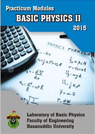
MODULPRACTICUM
GUIDE OF BASIC PHYSICS LABORATORY
I. PRELIMINARY
A. The purpose experiment of Basic Physics in Laboratory
Developing the theory and the fact that the material given in lectures more
internalized and to understand.
Checking the truth of the laws of physics and visually see some of the
events in the actual events.
Acquire the necessary skills and skills in using and understood the
usefulness of laboratory equipment.
Ability to analyze, create hypotheses or conclusions from the data obtained
from the experiments.
B. Experiment Steps
1. Preparation, with special attention to the purpose of the experiment,
comprehensively understand the theory and physical quantities
related to the experiment, the function of the tools and
experimental nets.
2. Experiment, with due regard to environmental conditions, perform repeated
measurements, record all of the data is done, including the
smallest scale.
3. Analysis, check the data consistent, make the relationship in the graph and
perform calculations correctly.
4 The authors report.
II. CONDUCT (MSUST READ)
A. Home / Before Practicum:
1. Practitioner has come late after the lab begins not allowed to participate in
practicum.
2. Learn well the modules that you do in the lab.
3. Work on the preliminary task in the module in question and submit it to
your assistant before working in the lab module.
3. 3
MODULPRACTICUM
4. At the time of leaving the lab will be sure to bring the control valve,
student identification, and lab coats.
5. In Laboratory practitioner should be calm, orderly, polite, well-dressed in
a shirt or collared shirt, do not wear sandals and shall wear identification.
Prohibited food, drink, or smoke in the laboratory.
6. Practitioners not allowed to participate if they do not meet the practical
requirements:
a. Wearing identification
b. Carry identification cards practicum
7. Submit the preliminary tasks to assistants and answer the initial test before
the lab begins.
B. DURING LABORATORY
1. Practitioners can begin the experiment after preliminary tests and get
permission from the assistant Instruction to use tool
2. Practitioners should get the data by experimenting. If they fail to to obtain
the data (due to equipment failure or other things), must report to the
assistant and lecturer responsible for the daily.
3. Practitioners must keep her safety, cleanliness and order laboratory
4. Special 4 for experiments using electricity, before turning on the power
supply ask the assistant if the circuit is correct.
5. If the practitioners make a faults, assistants can make a rule and sanction.
C. FINISHED EXPERIMENT
After the lab is complete, before leaving the laboratory, the practitioner must:
1. Ask a preliminary report which has been re-checked.
2. Ask the signature on the control card.
3. Cleaning the table and throw garbage.
4. 4
MODULPRACTICUM
D. OTHER PROVISIONS
1. Practicum must replace equipment damaged or lost during practicum takes
place with the same tool prior to attending next practicum.
2. The amount of practical value is 25% (1 sks) of the total value of college
Physics
3. Practicum is not a requirement to pass the course Physics II.
4. whole other rules will be explained at the time of general responsiveness
E. TIME LAB
Shift I 7:30 to 10:00 a.m
Shift II 10:00 to 12:30 p.m
Shift III 12:30 to 15:00 p.m
Shift IV 15.00 to 17.30 p.m
F. COPYRIGHT
This module was written by team of PASCO that Ann Hanks, Sean
McKeever and Geoffrey Clarion. Edited by crew of basic physic Laboratory.
Direction of Sabaruddin Rahman, ST.,MT.,Ph.D and As Responsible for the
laboratory
Gowa, 16th
February2015
CoordinatorPracticum
5. 5
MODULPRACTICUM
LIST OF CONTENTS
Chapter I : Electromagnetic :Faraday’s Law 13
Chapter II : Magnet: Magnetic Force onWire 16
Chapter III : Magnet: Magnetic Fields Coil
Chapter IV : Wave : Longitudinal And TransversalWave 19
Chapter V : Optic : Snell’s Law 25
6. 6
MODULPRACTICUM
CHAPTER I
ELECTROMAGNETIC
FARADAY’S LAW
I. INTRODUCTION
A changing magnetic field can produce a potential difference, often called
an emf, across a coil of wire. If the coil is part of a closed circuit, a current is
induced in the circuit. The changing magnetic field can be produced by relative
motion between a coil and a permanent magnet or by changing the current in one
coil that is placed near another coil. Effects of these kinds are known as
electromagnetic induction and can be described by Faraday’s law and Lenz’s law.
Motors, generators, and transformers are a few of the many common devices
whose operation is explained by the laws of electromagnetic induction. In this
experiment, a coil passes through a magnetic field, causing a change in the
magnetic flux in the coil.
II. PURPOSE
1. Verify faraday’s laws of electromagnetic induction
2. Observe factors which affect to magnitude of induced emf
3. Identify induced emf in the coil and the effect of the induced current on
the coil’s motion
III. EQUIPMENT
Induction Wand 200-turn EM-8099
Variable Gap Magnet EM-8618
Large Rod Stand ME-8735
45 cm Long Steel Rod ME-8736
Large Table Clamp ME-9507
Voltage-Current Sensor PS-2115
2-Axis Magnetic Field Sensor PS-2162
Rotary Motion Sensor PS-2120
7. 7
MODULPRACTICUM
Meter Stick
Computer and DataStudio Software
USB Link PS-2100
PASPORT Sensor Extension Cable PS-2500
IV. BASIC THEORY
According to Faraday's Law of Induction, a changing magnetic flux through
a coil induces an emf given by:
d
N
dt
E (1)
Where B dA BA
vv
for a magnetic field (B) which is constant over the
area (A) and perpendicular to the area. N is the number of turns of wire in the coil.
The negative sign in Faraday's law indicates that the induced emf and the change
in flux have opposite signs. This arises from significant physical phenomena,
referred to as Lenz' Law: the induced current is
Always in a direction that opposes the change of flux that created it. That is,
the induced current tends to keep the original magnetic flux from changing by
creating a magnetic field in a direction that opposes the change in flux.
V. SET-UP
1. Put a rod in the stand and clamp the cross-rod to it as shown in Figure 1. Put
the Rotary Motion Sensor at the end of the cross-rod.
2. Attach the coil wand to the Rotary Motion Sensor with the tabs on the 3-step
pulley just to the sides of the wand as shown in Figure 2.
3. Put the pole plates on the magnet as shown in Figure 3. Adjust the gap
between the magnet poles so the coil wand will be able to pass through but
put the magnet poles as close together as possible.
8. 8
MODULPRACTICUM
Figure 1: Rod Stand Figure 2: Tabs Figure 3: Magnet Pole Plate
4. Adjust the height of the coil so it is in the middle of the magnet. Align the
wand from side-to-side so it will swing through the magnet without hitting it.
5. Plug the Voltage Sensor into a USB Link or similar PASPORT interface.
Connect the interface into the computer. Repeat for the Rotary Motion Sensor
and the Magnetic Field Sensor.
6. Plug the Voltage Sensor banana plugs into the banana jacks on the end of the
coil wand. Drape the Voltage Sensor wires over the rods as shown in Figure 1
so the wires will not exert a torque on the coil as it swings. It helps to hold the
wires up while recording data.
7. Open the DataStudio file called "InducedEMFpas.ds".
VI. PROCEDURE
In this practicum, you will use an Induction Wand to measure the
relationship between induced electromotive force and magnetic flux with respect
to velocity of a coil traveling through magnetic field and strength of magnetic
field. Velocity of coil will be varying with changes the angle and strength of
magnetic field will be varying with changes the distance of magnets.
Before do the procedure below, determine which the north and south pole of
magnet.
9. 9
MODULPRACTICUM
a. Constant Distance (Varying velocity of coil)
1. Setup the distance between magnets, the distance is 4 cm.
2. With sensor far from magnets, Press TARE button at 2-Axis Magnetic
Sensor. Sensor will be calibrated
3. Click START BUTTON at top of DataSudio. Pull the coil wand back
with angle is 7,5 degree. Use Rotary Motion Sensor to see the angle. Let it
swing through the magnet.
4. Data will be recording. After around 6 waves at the graph, click STOP
button at DataStudio
5. Use MAGNIFIER tool to enlarge the portion of the graphs
6. Use mouse to highlight the first peak at Voltage graph and note the
maximum value of voltage
7. Use mouse to high light the first peak at Magnetic Field graph and note
the maximum value of voltage
8. Use mouse to high Light the first peak at Angular Velocity graph and note
the maximum value of velocity
9. Repeat steps 1-7 with angle 15°, 30°, 45°, and 60°
b. Constant Angle (Varying strength of magnetic field)
1. Setup the distance between magnets, the distance is 3,5 cm.
2. With sensor far from magnets, Press TARE button at 2-Axis Magnetic
Sensor. Sensor will be calibrated
3. Click START BUTTON at top of DataSudio. Pull the coil wand back
with angle is 30°. Use Rotary Motion Sensor to see the angle. Let it
swing through the magnet.
4. Data will be recording. After around 6 waves at the graph, click STOP
button at DataStudio
5. Use MAGNIFIER tool to enlarge the portion of the graphs
6. Use mouse to highlight the first peak at Voltage graph and note the
maximum value of voltage
7. Use mouse to high light the first peak at Magnetic Field graph and note
the maximum value of voltage
10. 10
MODULPRACTICUM
8. Repeat steps 1-7 with distance of magnets is 4 cm, 4,5 cm, 5 cm, 5,5 cm
and 6 cm
VII. DATA AND ANALYSIS
VII.1 TABLE
a. Constant Distance
Distance between magnets = 4 cm
Degree Angular velocity
(deg/s)
Magnetic Field (gauss) Voltage (volt)
7,5
15
30
45
60
75
b. Constant Angle
Angle of coil = 30 degree
Distance (cm) Magnetic Field (gauss) Voltage (volt)
3,5
4
4,5
5
5,5
6
11. 11
MODULPRACTICUM
VII.2 GRAPH
a. Constant Distance
b. Constant Angle
c. DataStudio Graph (x degree, x cm)
0
0.2
0.4
0.6
0.8
1
1.2
7.5 15 30 45 60
Voltage
Velocity
Velocity of coil vs Voltage
0
0.2
0.4
0.6
0.8
1
1.2
3.5 4 4.5 5 5.5 6
Voltage
Strength
Strength of Magnets vs Voltage
0
0.2
0.4
0.6
0.8
1
1.2
3.5 4 4.5 5 5.5 6
AxisTitle
Axis Title
12. 12
MODULPRACTICUM
VII.3 ANALYSIS
Answer the following question in your lab report:
1. How the relationship between velocity of coil through the magnet and
induced voltage? And Why?
2. How the relationship between magnitude of magnetic coil and induced
voltage? And Why?
3. Where the coil enter the magnet and leave the magnet at DataStudio graph?
4. Is the emf of the first peak positive or negative? Taking into account the
direction the wire is wrapped around the coil, does the sign of the emf
correspond to the direction expected using Lenz's Law?
5. Why is the induced voltage increasingly swing smaller and slower?
VIII. PRELIMINARY TASK
1. Write the factors that affect to the magnitude of induced voltage at swing coil
through the magnet!
2. Write faraday’s laws of induction of voltage and five applications in life!
3. Explain about magnetic field, magnetic flux, electric field, and eddy currents!
4. How to determine direction of induced current according to the Lenz’s law?
5. A coil have 200 turn which placed between two pole of permanent magnet
(north pole and south pole). Magnetic field B between two pole of magnets is
200 gauss. How much the magnetic flux if the outer diameter of coil is 3,1 cm
and inner diameter is 1,9 cm? If magnetic field is changing to 600 gauss in
2x10⁻² seconds. How much induced voltage at coil?
6. A bracelet copper is dropped between two pole of magnet with certain
strength magnetic field. Bracelet that drop appear slowed. Explain this
phenomenon!
REFERENCES
Hanks, Ann. Year. Faraday Induction (PASPORT) EX-995. PASCO: United
States of America
“The point of be a good engineers is think smart, honest, and work properly”
14. 14
MODULPRACTICUM
CHAPTER III
MAGNET
MAGNETIC FIELDS COIL
I. INTRODUCTION
The magnetic fields of various coils are plotted versus position as the
Magnetic Field Sensor is passed through the coils, guided by a track. The position
is recorded by a string attached to the Magnetic Field Sensor that passes over the
Rotary Motion Sensor pulley to a hanging mass.
It is particularly interesting to compare the field from Helmholtz coils at the
proper separation of the coil radius to the field from coils separated at less than or
more than the coil radius. The magnetic field inside a solenoid can be examined in
both the radial and axial directions.
II. EQUIPMENT
1 Helmholtz Coil Base EM-6715
2 Field Coil (2) EM-6711
1 Primary and Secondary Coils SE-8653
1 Patch Cords (set of 5) SE-9750
1 Patch Cords (set of 5) SE-9751
1 60 cm Optics Bench OS-8541
1 Dynamics Track Mount CI-6692
1 20 g hooked mass (Hooked Mass Set) SE-8759
2 Small Base and Support Rod (2) SE-9451
2 Optics Bench Rod Clamps (2) 648-06569
1 DC Power Supply SE-9720
1 Digital Multimeter SE-9786
1 Magnetic Field Sensor CI-6520A
1 Rotary Motion Sensor CI-6538
1 ScienceWorkshop 500 or 750 Interface CI-6400
1 DataStudio Software CI-6870
15. 15
MODULPRACTICUM
R
x
R
x
R
R
III. BASIC THEORY
III.1 Single Coil
For a coil of wire having radius R and
N turns of wire, the magnetic field
along the perpendicular axis through
the center of the coil is given by
III.2 Two Coils
Figure 2: Two Coils with Arbitrary Separation
For Helmholtz coils, the coil separation
(d) equals the radius (R) of the coils. This
coil separation gives a uniform magnetic
field between the coils. Plugging in
x = 0 gives the magnetic field at a point on
the x-axis centered between the two coils:
IV. PROCEDURE
1. Arranging track already provided with coil and coil base buffer between track.
2. Arranging experimental tools appropriate with the experimental picture.
3. Calculate the strength of the magnetic field resulting by changing the input
voltage (0, 4, 8, 12, 16) V and record the resulting current in the table provided.
4. Draw a graph resulting from each experiment.
5. Repeating the experiments 1 till 4 with 2 coils experiment.
RR
d
x
B1B2
x
16. 16
MODULPRACTICUM
V. ANALYSIS DATA
V.1 TABLE
a. Single Coil
V variable x constant 15 cm
V (Volt) I (ampere) B
0
4
8
12
16
b. Two coil
V variable x constant 15 cm
Seri
V (Volt) I (ampere) B
0
4
8
12
16
Parallel
V (Volt) I (ampere) B
0
4
8
12
16
17. 17
MODULPRACTICUM
V.2. GRAPH
DataStudio Graph
V.3 ANALYSIS
For analysis data, write in your lab report what and how much different
with analysis of theory and analysis of practicum/experiment. Answer the
following question in your lab report:
1. How the different between voltage single coil through the magnet and
double/two coil?
2. At Data Studio graph, what happen with voltage when the coil enter, leave
and at the center of magnet?
VI. PRELIMINARY TASK
1. Explain about:
a. Oersted d. Stream g. Entanglement
b. Faraday e. Tension h. Jumper
c. Lorentz f. Coil
2. The working principle of the power supply?
3. the principle of working of analog and digital multimeter and the advantages
their respective?
4. The working principle of magnetic field sensors and sensor rotation
REFERENCES
Hanks, Ann. Year. Faraday Induction (PASPORT) EX-995. PASCO: United
States of America
“Good people not look from their rhetoric but what your act for around”
0
0.2
0.4
0.6
0.8
1
1.2
3.5 4 4.5 5 5.5 6
AxisTitle
Axis Title
18. 18
MODULPRACTICUM
CHAPTER IV
WAVE
LONGITUDINAL AND TRANSVERSAL WAVE
I. PURPOSE
a. Shows the stationary transverse wave on a string and longitudinal waves in
spring
b. Know the relation between wave propagation speed (v) with the rope tension
force (F).
c. Determining the rapid propagation of waves on a string.
II. EQUIPMENT
Mechanical Driver, PASCO Model SF-9324 or WA-9753
Function Generator with Amplifier, PASCO Model PI-9587A or PI-9598
Support for the non-driven end of the spring.
Physics (Braided) String SE-8050
III. BASIC THEORY
Under thedirection of vibrationwavescan be dividedinto 2types:
1. Transverse waves, iewavesthathas a vibration directionperpendicular to the
directionrambatannya.Example: waves on a string, belombangonthe surface
of thewater, light waves,
2. Longitudinal waves, iewaves thathas a vibration directionin the direction
oframbatannya, Example: waveinspring, sound waves
A stretched string has many natural modes of vibration (three examples
are shown below). If the string is fixed at both ends then there must be a node
(place of no amplitude) at each end and at least one anti-node (place of
maximum amplitude). It may vibrate as a single segment, in which case the
length (L) of the string is equal to 1/2 the wavelength () of the wave. It may
also vibrate in two segments with a node at each end and one node in the
19. 19
MODULPRACTICUM
middle; then the wavelength is equal to the length of the string. It may also
vibrate with a larger integer number of segments. In every case, the length of
the string equals some integer number of half wavelengths.
If you drive a stretched string at an arbitrary frequency, you will
probably not see any particular mode: Many modes will be mixed together.
But, if the driving frequency, the tension and the length are adjusted correctly,
one vibrational mode will occur at much greater amplitude than the other
modes.
In this experiment, standing waves are set up in a stretched string by the
vibrations of an electrically-drive String Vibrator. The arrangement of the
apparatus is shown below. The tension in the string equals the weight of the
masses suspended over the pulley. You can alter the tension by changing the
masses. You can adjust the amplitude and frequency of the wave by adjusting
the output of the Sine Wave Generator, which powers the string vibrator.
L is the length of the vibrating part of the string and λ is the wavelength of the
wave. For the string shown above vibrating in 3 segments, λ= ⅔ L.
1
2
3
2 1
20. 20
MODULPRACTICUM
For any wave with wavelength and frequency f, the speed of the wave, v, is
v = f (1)
In addition, the speed of a wave on a string is also given by
(2)
The linear density () is the mass per unit length of the string. The Tension (F) is applied by
the hanging a mass (m), and is equal to the weight (mg) of the hanging mass.
IV. PROCEDURE
1. Hook one end of the spring
through the hole in the banana
plug assembly.
2. Insert the banana plug on one
end of the spring into the drive
shaft of the Mechanical Driver.
3. Suspend the other end of the
spring from a ring stand or other
support such that the length of
the spring is between 30 and 60
cm. (It may be desirable to tape
the loop on the end of the spring
to the support so that it does not
move once resonance is
attained.)
4. Connect the Mechanical Driver to a function generator capable of driving
a speaker. (The PASCO PI-9587B Digital Function Generator/Amplifier is
excellent for this purpose.)
5. Start driving the Mechanical Driver at about 10 Hz with approximately 1
mm of amplitude and slowly increase the frequency. At various
frequencies it will be noted that certain parts of the spring seem to stand
still (nodes) while others oscillate rapidly (anti-nodes). As the frequency is
v F
---=
21. 21
MODULPRACTICUM
increased the number of
nodes and anti-nodes will
increase and the distance
between them become
shorter. It may be
necessary to decrease the
driving amplitude when
resonant points are attained.
6. Graph the relation between the number of nodes and the driving
frequency. Change the length (thus the tension) of the spring and see if
different frequencies are required for the same number of nodes.
V. TABLE OF DATA
A. Longitudinal Wave
1. Constant voltage
Length of spring : 60 cm
Frequency (f)
Hz
Antinode
Speed of the wave (v)
m/s
30
40
50
60
2. Constant frequency : 60 Hz
Length of spring : 60 cm
Voltage Antinode
Speed of the wave (v)
m/s
1
2
3
4
5
.....
22. 22
MODULPRACTICUM
B. Transverse Wave
1. Constant voltage: 10 V
Length of string : 100 cm
Frequency (f)
Hz
Antinode
Speed of the wave (v)
m/s
25
30
35
40
45
50
2. Constant frequency : 50 Hz
Length of string : 100 cm
Frequency (f)
Hz
Antinode
Speed of the wave (v)
m/s
5
6
7
8
9
VI. PRELIMINARY TASK
1. What ismeant bythe wavesandvibrations?
2. Explainthe differencebetweentransverse wavesandlongitudinal waves!
3. What is adeviation, amplitude, frequency, andperiod?
4. Explainthe relationshipbetweenperiodandfrequency!
5. Writein the form ofthe formula, the relationshipbetweenwavespeed,
wavelength, andfrequencyfor the objectthatthe medium vibrate!
6. Within4seconds there aretwoocean wavespassingwhenthe distancebetweenthe
top and bottomwaves6meters, what is the propagationof theoceanwaves?
REFERENCES
Hanks, Ann. Year. Faraday Induction (PASPORT) EX-995. PASCO.
CHAPTER V
23. 23
MODULPRACTICUM
OPTIC
SNELL’S LAW
I. BASIC THEORY
WillebrordSnellius (1580–1626), the law was first accurately
described by the scientist Ibn Sahlat the Baghdad court in 984. In the
manuscript On Burning Mirrors and Lenses, Sahl used the law to derive lens
shapes that focus light with no geometric aberrations.
Snell's law states that the ratio of the sine of the angles of incidence
and refraction is equivalent to the ratio of phase velocities in the two media, or
equivalent to the reciprocal of the ratio of the indices of refraction:
For light crossing the boundary between two transparent materials,
Snell’s Law states n1sin θ1 = n2sin θ2 where θ1 is the angle of incidence, θ2 is
the angle of refraction, and n1 and n2 are the respective indices of refraction of
the materials (see below).
VII. PROCEDURE
24. 24
MODULPRACTICUM
1. Experiment 1: Reversibility
a. Equipment:
Ray Table
D-Shaped Lens
Light Source
b. Purpose.
In Trial 1 of this experiment, you will determine the relationship
between the angle of incidence and the angle of refraction for light passing
from air into a more optically dense medium (the acrylic of the D-shaped
lens). In Trial 2, you will determine whether the same relationship holds
between the angles of incidence and refraction for light passing out of a
more optically dense medium back into air. That is to say, if the light is
traveling in the opposite direction through the lens, is the law of refraction
the same or different? By comparing the results of both trials, you will find
the answer to this question. In Figure below, notice that refraction occurs
only at the flat surface of the D-shaped lens, not at the curved surface.
c. Setup
1. Place the light source in ray-box mode on a flat tabletop. Turn the wheel
to select a single ray.
2. Put the ray table in front of the light source so the ray from the light
source crosses the exact center of the ray table.
3. Put the D-shaped lens on the ray table exactly centered in the marked
outline.
Record Data
25. 25
MODULPRACTICUM
d. Trial 1
1. Turn the ray table so the incoming ray enters the lens through the flat
surface
2. Rotate the ray table to set the angle of incidence to each of the values
listed in the first column of Table For each angle of incidence (θi1),
observe the corresponding angle of refraction (θr1) and record it in the
second column of the table.
Trial 2
1. Copy all of the values in the second column to the third column of the
table. (In other words, the angles of refraction that you observe in Trial 1
will be the angles of incidence that you use in Trial 2.)
2. Turn the ray table so the incoming ray enters the lens through the curved
surface.
3. For the angles of incidence (θi2) that you wrote in the third column of the
table, observe the corresponding angles of refraction (θr2) and record them
in the fourth column
2. Experiment 2: Snell’s Law
a. Tool:
Light Source
Trapezoid from Ray Optics Kit
26. 26
MODULPRACTICUM
White paper
b. Purpose
The purpose of this experiment is to determine the index of refraction of
the acrylic trapezoid. For rays entering the trapezoid, you will measure the
angles of incidence and refraction and use Snell’s Law to calculate the index
of refraction.
c. Procedure
1. Place the light source in ray-box mode on a sheet of white paper. Turn the
wheel to select a single ray.
2. Place the trapezoid on the paper and position it so the ray passes through
the parallel sides as shown in Figure
3. Mark the position of the parallel surfaces of the trapezoid and trace the
incident and transmitted rays. Indicate the incoming and the outgoing rays
with arrows in the appropriate directions. Carefully mark where the rays
enter and leave the trapezoid.
4. Remove the trapezoid and draw a line on the paper connecting the points
where the rays entered and left the trapezoid. This line represents the ray
inside the trapezoid.
5. Choose either the point where the ray enters the trapezoid or the point
where the ray leaves the trapezoid. At this point, draw the normal to the
surface.
6. Measure the angle of incidence (θi) and the angle of refraction with a
protractor. Both of these angles should be measured from the normal.
Record the angles in the first row of Table below
7. On a new sheet of paper, repeat steps 2–6 with a different angle of
incidence. Repeat these steps again with a third angle of incidence. The
first two columns of Table below should now be filled.
27. 27
MODULPRACTICUM
3. Experiment 3: Prisma
a. Tool:
Light Source
Trapezoid from Ray Optics Kit
Blank white paper
b. Purpose
The purpose of this experiment is to show how a prism separates
white light into its component colors and to show that different colors are
refracted at different angles through a prism.
c. Procedure
1. Place the light source in ray-box mode on a sheet of blank white paper.
Turn the wheel to select a single white ray.
2. Position the trapezoid as shown in Figure 2.2. The acute-angled end of
the trapezoid is used as a prism in this experiment. Keep the ray near the
point of the trapezoid for maximum transmission of the light.
28. 28
MODULPRACTICUM
VIII. PRELIMINARY TASK
1. Explain about:
a. Dispertion
b. Reflection
c. Snell’s Law
d. Ibnu Sahl
e. Deviation Angle
f. Refraction
g. Convex lens
h. Concav lens
i. Prisma
j. Polikromatic rays
k. Monokromatic rays
2. Find the refraction index of lens if light coming from the angle 60 degrees
and have 50 degrees angle refraction!
3. Explain how a vapor on the highway is viewed when see from a distance!
4. A prism has a refracting angle of 60 ° is made of glass refractive index of
1.50. A beam of light comes on one side of the field prism with the angle
of incidence of 30 °. What size deviation angle.
REFERENCES
Geoffrey Clarion. Newton’s 2 Law. Pasco : United State Of America
“Be honestyandhopefully we willallbea reliabletechnocrats”